EP0544660B1 - Process for combatting pollution of the environment caused by refuse material, and collecting device for carrying out said method - Google Patents
Process for combatting pollution of the environment caused by refuse material, and collecting device for carrying out said method Download PDFInfo
- Publication number
- EP0544660B1 EP0544660B1 EP19900913284 EP90913284A EP0544660B1 EP 0544660 B1 EP0544660 B1 EP 0544660B1 EP 19900913284 EP19900913284 EP 19900913284 EP 90913284 A EP90913284 A EP 90913284A EP 0544660 B1 EP0544660 B1 EP 0544660B1
- Authority
- EP
- European Patent Office
- Prior art keywords
- waste
- identification
- collection unit
- voucher
- gift
- Prior art date
- Legal status (The legal status is an assumption and is not a legal conclusion. Google has not performed a legal analysis and makes no representation as to the accuracy of the status listed.)
- Expired - Lifetime
Links
Images


Classifications
-
- B—PERFORMING OPERATIONS; TRANSPORTING
- B65—CONVEYING; PACKING; STORING; HANDLING THIN OR FILAMENTARY MATERIAL
- B65F—GATHERING OR REMOVAL OF DOMESTIC OR LIKE REFUSE
- B65F1/00—Refuse receptacles; Accessories therefor
- B65F1/0033—Refuse receptacles; Accessories therefor specially adapted for segregated refuse collecting, e.g. receptacles with several compartments; Combination of receptacles
-
- G—PHYSICS
- G07—CHECKING-DEVICES
- G07F—COIN-FREED OR LIKE APPARATUS
- G07F7/00—Mechanisms actuated by objects other than coins to free or to actuate vending, hiring, coin or paper currency dispensing or refunding apparatus
- G07F7/06—Mechanisms actuated by objects other than coins to free or to actuate vending, hiring, coin or paper currency dispensing or refunding apparatus by returnable containers, i.e. reverse vending systems in which a user is rewarded for returning a container that serves as a token of value, e.g. bottles
-
- B—PERFORMING OPERATIONS; TRANSPORTING
- B65—CONVEYING; PACKING; STORING; HANDLING THIN OR FILAMENTARY MATERIAL
- B65F—GATHERING OR REMOVAL OF DOMESTIC OR LIKE REFUSE
- B65F1/00—Refuse receptacles; Accessories therefor
- B65F1/0033—Refuse receptacles; Accessories therefor specially adapted for segregated refuse collecting, e.g. receptacles with several compartments; Combination of receptacles
- B65F2001/008—Means for automatically selecting the receptacle in which refuse should be placed
-
- B—PERFORMING OPERATIONS; TRANSPORTING
- B65—CONVEYING; PACKING; STORING; HANDLING THIN OR FILAMENTARY MATERIAL
- B65F—GATHERING OR REMOVAL OF DOMESTIC OR LIKE REFUSE
- B65F2210/00—Equipment of refuse receptacles
- B65F2210/152—Material detecting means
- B65F2210/1525—Material detecting means for metal
-
- B—PERFORMING OPERATIONS; TRANSPORTING
- B65—CONVEYING; PACKING; STORING; HANDLING THIN OR FILAMENTARY MATERIAL
- B65F—GATHERING OR REMOVAL OF DOMESTIC OR LIKE REFUSE
- B65F2210/00—Equipment of refuse receptacles
- B65F2210/168—Sensing means
-
- Y—GENERAL TAGGING OF NEW TECHNOLOGICAL DEVELOPMENTS; GENERAL TAGGING OF CROSS-SECTIONAL TECHNOLOGIES SPANNING OVER SEVERAL SECTIONS OF THE IPC; TECHNICAL SUBJECTS COVERED BY FORMER USPC CROSS-REFERENCE ART COLLECTIONS [XRACs] AND DIGESTS
- Y02—TECHNOLOGIES OR APPLICATIONS FOR MITIGATION OR ADAPTATION AGAINST CLIMATE CHANGE
- Y02W—CLIMATE CHANGE MITIGATION TECHNOLOGIES RELATED TO WASTEWATER TREATMENT OR WASTE MANAGEMENT
- Y02W30/00—Technologies for solid waste management
- Y02W30/10—Waste collection, transportation, transfer or storage, e.g. segregated refuse collecting, electric or hybrid propulsion
Definitions
- the present invention relates to a method of combating pollution of the environment by waste, and a device for implementing this method, according to the first part of claims 1 and 12 (for example GB-A-2 224 922) .
- the purpose of the identification means is to prevent any object from being introduced into the collection unit and giving rise to proof of deposit. They will depend on the type of waste for which the collection unit is intended, a type which is itself a function of the location of said unit. They may also depend on other objectives such as the collection of precise waste as to their origin or their nature, as will be seen below.
- Proof of deposit could be, for example, a fraction of free admission to a cinema or a racetrack, a reduction voucher on the purchase of a product of the same origin as that of the waste deposited, etc. .
- the identification of the waste is done, at least partially, by comparison between a dimension of at least part of the waste and those of said access orifice. This type of identification prevents objects whose size obviously does not correspond to the type of waste expected to be introduced into the collection unit.
- the method according to the invention proposes to attach, to the consumable product sold, a sachet suitable for collecting the packaging of said product and / or the waste resulting from the product after consumption, and it is characterized in that it consists in providing on said bag said proof of deposit and in providing the collection unit with separation means, marking and for restoring said proof of deposit, which means act on the sachet while it is introduced and / or conveyed into the collection unit.
- the sachet is a fragment of the sachet which serves as proof of deposit.
- the sachet can be tear-resistant by hand (non-woven sachet with possibly reinforcing fibers).
- the marking carried out by the collection unit may be composting, a perforation or a characteristic trace left by the separation means and it will confirm that the proof of deposit has been delivered by the collection unit.
- the identification of the waste may consist of a recognition of a property of a material making up the waste, such as its magnetic or non-magnetic character. It may also consist of recognition of a standard section of the waste. The identification of the scrap can be further clarified by crossing the two pieces of information.
- the identification can be further refined by reading the dominant color of the scrap and / or that of a bar code carried by the scrap.
- the identification only relates to a characteristic if the objective is to recover a certain category of recyclable waste, for example magnetic waste.
- the identification of the scrap is done before sorting into recognized scrap and accepted for collection in a main container and in unrecognized waste and diverted to a secondary container, only accepted waste being taken into account for the delivery of proof of deposit.
- the invention extends its scope to a collection unit for implementing the method according to the invention.
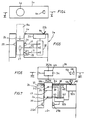
- a waste collection unit generally designated by 1, formed of a container 2 surmounted by an operational block 3. This the latter has an access or introduction slot 4 for a waste bag, a proof of deposit ejection slot 6 and a lateral actuation lever or crank 7.
- the width of the access slot 4 is too small for the fingers to be inserted therein.
- the block 3 determines a path 8 for transporting the waste bag 19, part of which consists of an endless conveyor 9 stretched over cylinders 10 ⁇ and 11.
- the cylinder 10 ⁇ is pressed against a drive cylinder 12 on the axis of rotation 13 from which aqit the crank 7.
- This drive cylinder 12 is, in fact, in two parts 12a and 12b between which is locked a circular knife 14 with wavy blade 14a.
- the path 8 splits into an ejection path 15 following the cylinder 12a and a collection path 16 following the cylinder 12b.
- the ejection path 15 opens out of the block 3 through the slot 6, while the collection path 16 ends between the cylinder 11 and a pressure cylinder 17, facing each other, after having determined a ramp 18 folding down.
- the actuation of the crank 7 rotates said cylinder 12, therefore the cylinder 10 ⁇ , the conveyor 9 and at the same time the cylinders 11 and 17.
- the rotation of the cylinders 10 ⁇ and 12 snaps the bag between them, which bag passes entirely into the slot 4 and is routed beyond said cylinders.
- the knife 14, which is blocked on the axis of rotation 13 rotates at the same time as it by cutting the bag 19 along the line 21.
- the access orifice 4a of the block 3a is circular, with a diameter very slightly greater than the diameter of the product or products 19a whose collection is desired, this to avoid that scrap whose section has a dimension greater than the diameter of the orifice 4a can be introduced into the unit.
- Block 3a has a downcomer 24 which opens into container 2.
- a magnetic metal detector consisting of a transmitter 25 and a receiver 26, and two color readers 27 and 28.
- the transmitter emits a field that receives the receiver, which records any disturbance of this field caused by the passage of a magnetic object.
- the color reader sends a light beam and receives in return the beam which is reflected to it by any object passing in front of it. It analyzes the reflected beam and, depending on the absorption observed, determines whether the object is of the expected color or not.
- Two color detectors are provided, arranged at 90 ° from one another to ensure that the color read is not that of a point area, but rather a dominant color.
- the output 29 of the receiver 26 provides directly, or via a known interface, a logic level "1" (for example) when it finds that the scrap is magnetic and a logic level "O" if it is not not.
- the output 30 ⁇ and 31 of the color readers 27 and 28 provide directly, or via a known interface, a logic level “1" (for example) when they find that the scrap is red and a logic level respectively "O" if it is not.
- the outputs 29-31 are connected to a logic control circuit 32, the output of which is connected by an interface not shown to a distributor 33 of proofs of deposit 22a.
- the device could include more color readers if the accuracy of the reading is to be increased and that the types of detectors mentioned above, both with regard to the magnetic or non-magnetic nature of the scrap, than its color dominant, are just examples among many others.
- the property detected could be other than the magnetic character.
- the access orifice 4b of the block 3b is rectangular and its section is very slightly greater than that, standard, of the briquettes 19b whose collection is desired, for the same reason as that set out above.
- the block 3b has a downcomer 24 which opens into the container 2. Along this downcomer are arranged three pairs of feelers 34, 35 and 36. The pair of feelers 35 is offset at 90 ° with respect to the pair probes 34 to ensure that the waste has a section corresponding to the standard section. The distance between the pair of feelers 34 and 36 is such that only a large format briquette 19b can touch them simultaneously.
- the outputs 37, 38 of the pair of probes 34, those 39, 40 ⁇ of the pair of probes 35 and those 41, 42 of the pair of probes 36 provide directly, or via a known interface, a logic level "1" (for example) when they are touched by the waste 19b during its fall in the conduit 24 and a logic level "O" if they are not.
- the outputs 37-42 are connected to a logic control circuit 32b, the output of which is connected by an interface not shown to a distributor 33b of proofs of deposit 22b or 22b ′.
- this embodiment could also include a detector of the nature of a material constituting the waste such as the assembly 25a, 25b, the output signal of which would be combined with the aforementioned signals. It could issue proof of deposit only for a given briquette format, in which case the pair of feelers 35 and the slot 4b ′ would be eliminated. Distributor 33b could also distribute proofs of deposits for small and large formats through a single slot.
- the unit according to the invention could be designed to accept, for example, briquettes of the same capacity, but of rectangular section different, a dimension of this section being however common to the different briquettes, called “small” and “large” sections.
- the opening 4b would have two of its opposite sides, called “standard spacing sides", the length of which would correspond to this common dimension, apart from the insertion clearance, the length of the opposite sides of the opening being chosen so as to allow the introduction of both small section and large section briquettes.
- the feelers could be arranged only along the walls of the conduit 24 which extend the standard spacing sides, if one does not try to distinguish, in the identification, the briquettes of small section of those of large section.
- FIG. 7 applies the incentive method according to the invention to the deposit of recyclable waste of a certain type.
- the downcomer 24 is provided with a transmitter 25c and with a receiver 26c, the output 29c of which is connected to a read-only memory 32c, itself connected by a interface not shown, to a distributor 33c of proof of deposit 22c and to a motor 43.
- the duct 24 is further provided with a passage detector, constituted for example by a photoelectric cell 48, 49, the output 50 ⁇ of the receiver 49 also being connected to read only memory 32c.
- a passage detector constituted for example by a photoelectric cell 48, 49, the output 50 ⁇ of the receiver 49 also being connected to read only memory 32c.
- a tank 44 blocked on an axis of rotation 45 controlled by the motor 43.
- a partition 46 separating a main container 20 ⁇ 1 a secondary container 20 ⁇ 2.
- the transmitter 25c and receiver 26c are sufficiently distant from the orifice 4c and a one-way passage device 47 equips said orifice.
- the read-only memory When the read-only memory receives the input signal 11 (passage of a magnetic material), it commands the distributor 33c to distribute a proof of deposit 22c, through the slot 6c, and to rotate the motor 43 so as to rotate the axis 45 in the direction of the arrow F1: the tank then empties of the waste 19c that it received in the container 20 ⁇ 1.
- the read-only memory receives the input signal 10 ⁇ (passage of a non-magnetic material)
- it does not send any order to the distributor 33c, but controls the rotation of the motor 43 so as to rotate the axis 45 in the direction of arrow F2: the tank then empties of the waste 19c in the container 20 ⁇ 2.
Abstract
Description
La présente invention concerne un procédé de lutte contre la pollution de l'environnement par des rebuts, et un dispositif pour la mise oeuvre de ce procédé, selon la première partie des revendications 1 et 12 (par exemple GB-A-2 224 922).The present invention relates to a method of combating pollution of the environment by waste, and a device for implementing this method, according to the first part of
En dépit des campagnes de propreté et de protection de l'environnement, et malgré la mise en place d'unités de collecte de rebuts de plus en plus nombreuses à la disposition du public, force est de constater que les lieux publics, en particulier au voisinage des commerces distribuant des produits alimentaires "à emporter", sont de plus en plus sales. Le phénomène n'épargne pas les salles de spectacles dont le sol même, après une séance, est jonché de petits rebuts divers (bâtons et sachets de crème glacés, papiers de bonbons, tickets, etc...), ni par exemple les hippodromes où les tickets de pari usagés finissent plus souvent sur les pelouses que dans les corbeilles à papier.Despite cleanliness and environmental protection campaigns, and despite the establishment of more and more waste collection units available to the public, it is clear that public places, particularly in neighborhood of shops distributing "take away" food products, are becoming increasingly dirty. This phenomenon does not spare performance halls, the very ground of which, after a session, is strewn with various small scraps (sticks and sachets of ice cream, candy papers, tickets, etc.), or for example racetracks where used bet tickets end up more often on lawns than in wastebaskets.
Il s'ensuit un enlaidissement général de l'environnement, une atteinte à l'hygiène dans le cas de déchets alimentaires (os de poulet, par exemple) et un budget de nettoyage considérable.This results in a general ugliness of the environment, an attack on hygiene in the case of food waste (chicken bones, for example) and a considerable cleaning budget.
Il serait donc souhaitable d'inciter la part du public qui est responsable de cette situation, et manisfestement insensible à l'intérêt de la collectivité, à utiliser néanmoins les unités de collecte de rebuts, et pour ce faire que cette part du public y trouve son intérêt personnel et immédiat.It would therefore be desirable to encourage the part of the public which is responsible for this situation, and manifestly insensitive to the interest of the community, to nevertheless use the refuse collection units, and for this purpose that this part of the public finds there his personal and immediate interest.
C'est le but que s'est fixé l'invention, but qui est atteint en ce sens qu'elle propose un procédé qui consiste à munir lesdites unités, de première part, de moyens adaptés à identifier au moins grossièrement un rebut présenté à, ou introduit dans, ledit orifice d'accès, de deuxième part, de moyens convoyeurs dudit rebut au-delà de l'orifice d'accès et, de troisième part, de moyens adaptés à délivrer et valider une preuve de dépôt, telle qu'un ticket cadeau, en rapport avec le rebut, après identification positive par lesdits moyens d'identification en combinaison éventuelle avec lesdits moyens convoyeurs.This is the aim which the invention has set itself, which is achieved in the sense that it proposes a method which consists in providing said units, firstly, with means adapted to identify at least roughly a scrap presented to , or introduced into, said access port, secondly, conveyor means of said waste beyond the access port and, thirdly, means adapted to deliver and validate proof of deposit, such as a gift voucher, in connection with the waste, after positive identification by said identification means in possible combination with said conveyor means.
Les moyens d'identification ont pour fonction d'éviter que n'importe quel objet puisse être introduit dans l'unité de collecte et donner lieu à une preuve de dépôt. Ils dépendront du type de rebuts auquel est destinée l'unité de collecte, type qui est lui-même fonction de l'implantation de ladite unité. Ils pourront également dépendre d'autres objectifs comme la collecte de rebuts précis quant à leur origine ou à leur nature, ainsi qu'on le verra plus loin.The purpose of the identification means is to prevent any object from being introduced into the collection unit and giving rise to proof of deposit. They will depend on the type of waste for which the collection unit is intended, a type which is itself a function of the location of said unit. They may also depend on other objectives such as the collection of precise waste as to their origin or their nature, as will be seen below.
La preuve de dépôt pourra être, par exemple, une fraction d'entrée gratuite dans une salle de cinéma ou dans un hippodrome, un bon de réduction sur l'achat d'un produit de la même origine que celle du rebut déposé, etc..Proof of deposit could be, for example, a fraction of free admission to a cinema or a racetrack, a reduction voucher on the purchase of a product of the same origin as that of the waste deposited, etc. .
Dans une première forme d'exécution de l'invention, l'identification du rebut se fait, au moins partiellement, par comparaison entre une dimension d'au moins une partie du rebut et celles dudit orifice d'accès. Ce type d'identification évite que des objets dont l'encombrement ne correspond évidemment pas au type de rebuts attendus puissent être introduits dans l'unité de collecte.In a first embodiment of the invention, the identification of the waste is done, at least partially, by comparison between a dimension of at least part of the waste and those of said access orifice. This type of identification prevents objects whose size obviously does not correspond to the type of waste expected to be introduced into the collection unit.
Dans le cas de produits consommables donnant des déchets de faible épaisseur, tels que ceux souillant habituellement le sol des salles de spectacles ainsi les tickets de pari dans les hippodromes, le procédé selon l'invention propose de joindre, au produit consommable vendu, un sachet adapté à recueillir le conditionnement dudit produit et/ou les déchets résultants du produit après consommation, et il est caractérisé en ce qu'il consiste à prévoir sur ledit sachet ladite preuve de dépôt et à munir l'unité de collecte de moyens de séparation, de marquage et de restitution de ladite preuve de dépôt, lesquels moyens agissent sur le sachet tandis qu'il est introduit et/ou convoyé dans l'unité de collecte.In the case of consumable products giving thin waste, such as those usually soiling the floor of performance halls and bet tickets in racetracks, the method according to the invention proposes to attach, to the consumable product sold, a sachet suitable for collecting the packaging of said product and / or the waste resulting from the product after consumption, and it is characterized in that it consists in providing on said bag said proof of deposit and in providing the collection unit with separation means, marking and for restoring said proof of deposit, which means act on the sachet while it is introduced and / or conveyed into the collection unit.
On comprend que, dans ce cas, c'est un fragment du sachet qui sert de preuve de dépôt. Pour éviter les fraudes, le sachet pourra être indéchirable à la main (sachet en non tissé avec éventuellement des fibres de renforcement). Le marquage effectué par l'unité de collecte pourra être un compostage, une perforation ou une trace caractéristique laissée par les moyens de séparation et il confirmera que la preuve de dépôt a bien été délivrée par l'unité de collecte.It is understood that, in this case, it is a fragment of the sachet which serves as proof of deposit. To avoid fraud, the sachet can be tear-resistant by hand (non-woven sachet with possibly reinforcing fibers). The marking carried out by the collection unit may be composting, a perforation or a characteristic trace left by the separation means and it will confirm that the proof of deposit has been delivered by the collection unit.
Dans le cas de rebuts plus volumineux, tels que les bôites métalliques ayant contenu une boisson, que dans la suite on appellera "cannettes", ou les emballages parallèlépipédiques rectangles en carton chemisé intérieurement d'une feuille métallique, que dans la suite on appellera "briquettes", il est possible de se passer de l'utilisation d'un sachet collecteur et de procéder à des identifications plus spécifiques.In the case of more voluminous rejects, such as the metal boxes having contained a drink, which in the following will be called "cans", or the rectangular parallelepiped packaging made of cardboard internally lined with a metallic sheet, which in the following will be called " briquettes ", it is possible to dispense with the use of a collecting bag and to carry out more specific identifications.
Ainsi, dans de telles applications, l'identification du rebut pourra consister en une reconnaissance d'une propriété d'un matériau composant le rebut, telle que son caractère magnétique ou amagnétique. Elle pourra également consister en une reconnaissance d'une section standard du rebut. L'identification du rebut pourra encore être précisée en croisant les deux informations.Thus, in such applications, the identification of the waste may consist of a recognition of a property of a material making up the waste, such as its magnetic or non-magnetic character. It may also consist of recognition of a standard section of the waste. The identification of the scrap can be further clarified by crossing the two pieces of information.
L'identification pourra être affinée davantage par la lecture de la couleur dominante du rebut et/ou celle d'un code à barres porté par le rebut.The identification can be further refined by reading the dominant color of the scrap and / or that of a bar code carried by the scrap.
Il peut toutefois suffire que l'identification ne porte que sur une caractéristique si l'objectif est de procéder à une récupération d'une certaine catégorie de rebuts recyclables, par exemple des rebuts magnétiques.However, it may suffice that the identification only relates to a characteristic if the objective is to recover a certain category of recyclable waste, for example magnetic waste.
Dans ce cas, selon l'invention, l'identification du rebut se fait préalablement à un tri en rebuts reconnus et acceptés pour collecte dans un conteneur principal et en rebuts non reconnus et dérivés vers un conteneur secondaire, seuls les rebuts acceptés étant pris en compte pour la délivrance de la preuve de dépôt.In this case, according to the invention, the identification of the scrap is done before sorting into recognized scrap and accepted for collection in a main container and in unrecognized waste and diverted to a secondary container, only accepted waste being taken into account for the delivery of proof of deposit.
L'invention étend sa portée à une unité de collecte pour la mise en oeuvre du procédé selon l'invention.The invention extends its scope to a collection unit for implementing the method according to the invention.
D'autres avantages et caractéristiques avantageuses de l'invention ressortiront de la description qui va suivre, faite en référence aux dessins annexés dans lesquels :
- la figure 1 est une vue en perspective de la partie supérieure d'une unité de collecte selon l'invention, adaptée à recueillir des rebuts de faible épaisseur, sous sachet.
- les figures 2a-2c sont des vues schématiques du dessus de la partie opérationnelle, ou bloc opérationnel, de l'unité de la figure 1, montrant trois phases de traitement d'un sachet de rebuts avec éjection d'une preuve de dépôt,
- les figures 3a-3b sont des coupes prises respectivement selon la ligne III-III des figures 2a-2c,
- la figure 4 est une vue de dessus du bloc opérationnel d'une unité de collecte adaptée à recueillir des cannettes,
- la figure 5 est une vue en coupe schématique prise selon la ligne IV-IV de la figure 4,
- la figure 6 est une vue de dessus du bloc opérationnel d'une unité de collecte adaptée à recueillir des briquettes,
- la figure 7 est une vue en coupe schématique prise selon la ligne VI-VI de la figure 6, et
- la figure 8 est une vue en coupe schématique du bloc opérationnel d'une unité de collecte et de tri pour la récupération de rebuts recyclables.
- Figure 1 is a perspective view of the upper part of a collection unit according to the invention, adapted to collect scrap of small thickness, in a bag.
- FIGS. 2a-2c are schematic views from above of the operational part, or operational block, of the unit of FIG. 1, showing three phases of processing a bag of rejects with ejection of a proof of deposit,
- FIGS. 3a-3b are sections taken respectively along the line III-III of FIGS. 2a-2c,
- FIG. 4 is a top view of the operational block of a collection unit suitable for collecting cans,
- FIG. 5 is a schematic sectional view taken along line IV-IV of FIG. 4,
- FIG. 6 is a top view of the operational block of a collection unit suitable for collecting briquettes,
- FIG. 7 is a schematic sectional view taken along line VI-VI of FIG. 6, and
- Figure 8 is a schematic sectional view of the operational block of a collection and sorting unit for the recovery of recyclable waste.
Si l'on se réfère à la figure 1, on voit une unité de collecte de rebuts, désignée dans son ensemble par 1, formée d'un conteneur 2 surmonté d'un bloc opérationnel 3. Ce dernier présente une fente 4 d'accès ou d'introduction pour un sachet de rebuts, une fente 6 d'éjection de preuve de dépôt et une manette ou manivelle d'actionnement 7 latérale. La largeur de la fente d'accès 4 est trop faible pour que l'on puisse y introduire les doigts.If we refer to FIG. 1, we see a waste collection unit, generally designated by 1, formed of a
Comme il ressort des figures 2a et 3a, le bloc 3 détermine une voie 8 de transport du sachet 19 de rebuts dont une partie est constituée d'un convoyeur sans fin 9 tendu sur des cylindres 10̸ et 11. Le cylindre 10̸ est en appui contre un cylindre d'entraînement 12 sur l'axe de rotation 13 duquel aqit la manivelle 7. Ce cylindre d'entraînement 12 est, en fait, en deux parties 12a et 12b entre lesquelles est bloqué un couteau circulaire 14 à lame ondulée 14a.As can be seen in FIGS. 2a and 3a, the
Au delà des cylindres 10̸ et 12, la voie 8 se scinde en une voie d'éjection 15 faisant suite au cylindre 12a et une voie de collecte 16 faisant suite au cylindre 12b. La voie d'éjection 15 débouche à l'extérieur du bloc 3 par la fente 6, tandis que la voie de collecte 16 aboutit entre le cylindre 11 et un cylindre presseur 17, en vis-à-vis, après avoir déterminé une rampe 18 de rabattage.Beyond the cylinders 10̸ and 12, the
Le fonctionnement du dispositif est le suivant : un sachet 19, imprimé d'une mention "Bon pour..." (ou autre) dans la zone immédiatement voisine de son bord libre, est introduit dans le fente 4 avec son bord libre tourné vers la manivelle 7 jusqu'à ce qu'il vienne en butée contre les cylindres 10̸ et 12 (figures 2a et 3a). L'actionnement de la manivelle 7 entraîne en rotation ledit cylindre 12, donc le cylindre 10̸, le convoyeur 9 et du même coup les cylindres 11 et 17. La rotation des cylindres 10̸ et 12 happe le sachet entre eux, lequel sachet passe entièrement dans le fente 4 et est acheminé au delà desdits cylindres. Au passage, le couteau 14, qui est bloqué sur l'axe de rotation 13, tourne en même temps que lui en découpant le sachet 19 selon la ligne 21. Ce faisant, l'ondulation de son arête 14a laisse une marque caractéristique sur ladite ligne. La zone découpée 22 formant preuve de dépôt est déviée selon la voie d'éjection 15 et émerge à l'extérieur du bloc 3 par la fente 6. La zone 23 formant le nouveau bord libre du sachet 19 est, elle, contrainte de passer dans le système de rampe 18 qui la rabat sur elle-même avant qu'elle atteigne les cylindres 11 et 17 (figures 2b et 3b). Ces cylindres ont un effet presseur sur le rabat afin d'en marquer le pli et de refermer le sachet 19 avant qu'il ne soit évacué par une chute appropriée, non représentée, dans le conteneur 2 (figures 2c et 3c).The operation of the device is as follows: a
La simplicité et la robustesse de cette structure la rendent apte à être placée dans des lieux publics. Au lieu d'une manivelle tournant une ou plusieurs fois sur 360̸°, on pourrait avoir recours, moyennant une démultiplication appropriée, à un manette pivotant sur un angle inférieur ou égal à 180̸°. Dans un lieu protégé, le fonctionnement de la machine pourra être électrique. Par ailleurs, le couteau pourrait avoir une lame non ondulée, auquel cas le marquage serait fait à l'aide de moyens perforateurs ou composteurs prévus le long de la voie d'éjection 15.The simplicity and robustness of this structure make it suitable for being placed in public places. Instead of a crank rotating one or more times through 360̸ °, one could have recourse, by means of an appropriate reduction, to a lever pivoting on an angle less than or equal to 180̸ °. In a protected place, the operation of the machine may be electric. Furthermore, the knife could have a non-wavy blade, in which case the marking would be done using perforator or composter means provided along the
Le mode de réalisation illustré aux figures 4 et 5, dans lesquelles on utilisera les mêmes références qu'aux figures 1-3c pour désigner les mêmes pièces et les mêmes références, mais suivies de la lettre a pour désigner des pièces similaires, convient à la collecte de cannettes d'une certaine marque ayant une couleur dominante.The embodiment illustrated in Figures 4 and 5, in which the same references will be used as in Figures 1-3c to designate the same parts and the same references, but followed by the letter a to designate similar parts, is suitable for the collection of cans of a certain brand with a dominant color.
A cette fin, au lieu d'être en forme de fente, l'orifice d'accès 4a du bloc 3a est circulaire, avec un diamètre très faiblement supérieur au diamètre du ou des produits 19a dont la collecte est souhaitée, ce pour éviter que des rebuts dont la section présente une dimension supérieure au diamètre de l'orifice 4a puissent être introduits dans l'unité.To this end, instead of being in the form of a slot, the
Le bloc 3a comporte un conduit de descente 24 qui débouche dans le conteneur 2. Le long de ce conduit de descente sont disposés un détecteur de métaux magnétiques, constitué d'un émetteur 25 et d'un récepteur 26, et deux lecteurs de couleurs 27 et 28. L'émetteur émet un champ que reçoit le récepteur, lequel enregistre toute pertubation de ce champ occasionnée par le passage d'un objet magnétique. Le lecteur de couleur envoie un faisceau lumineux et reçoit en retour le faisceau qui lui est réfléchi par tout objet passant devant lui. Il analyse le faisceau réfléchi et, selon l'absorption constatée, détermine si l'objet est de la couleur attendue au non.Block 3a has a
Il est prévu deux détecteurs de couleurs disposés à 90̸° l'un de l'autre pour s'assurer que la couleur lue n'est pas celle d'une zone ponctuelle, mais bien une couleur dominante.Two color detectors are provided, arranged at 90 ° from one another to ensure that the color read is not that of a point area, but rather a dominant color.
La sortie 29 du récepteur 26 fournit directement, ou via une interface connue en soi, un niveau logique "1" (par exemple) lorsqu'il constate que le rebut est magnétique et un niveau logique "O" s'il ne l'est pas.The
De même, la sortie 30̸ et 31 des lecteurs de couleur 27 et 28 fournissent directement, ou via une interface connue en soi, un niveau logique "1" (par exemple) lorsqu'ils constatent respectivement que le rebut est rouge et un niveau logique "O" s'il ne l'est pas.Similarly, the output 30̸ and 31 of the
Les sorties 29-31 sont reliées à un circuit logique de commande 32 dont la sortie est reliée par une interface non représentée à un distributeur 33 de preuves de dépôt 22a.The outputs 29-31 are connected to a
Dans un mode de mise en oeuvre préféré, le circuit logique de commande 32 est une mémoire morte dont les entrées d'adressage e1-e3 sont reliées aux sorties 29-31. Cette mémoire peut être programmée de la façon suivante :
- si l'on a 111 comme signal d'entrée la mémoire 32 envoie au distributeur 33 l'ordre de délivrer une preuve de dépôt 22a par la fente 6a,
- pour tous les autres signaux d'entrée
0̸11 : matériau amagnétique ayant le rouge comme couleur dominante
0̸0̸1 ou 0̸10̸ : matériau amagnétique ayant une zone limitée rouge
110̸ ou 10̸1 : matériau magnétique ayant une zone limitée rouge
0̸0̸0̸ : matériau ni magnétique ni rouge
la mémoire n'envoie aucun ordre de délivrance au distributeur.In a preferred embodiment, the
- if there is 111 as an input signal, the
memory 32 sends thedistributor 33 the order to deliver proof ofdeposit 22a through theslot 6a, - for all other input signals
0̸11: non-magnetic material with red as color dominant
0̸0̸1 or 0̸10̸: non-magnetic material with a limited red area
110̸ or 10̸1: magnetic material with a limited red area
0̸0̸0̸: neither magnetic nor red material
the memory does not send any delivery order to the distributor.
Il est bien entendu que le dispositif pourrait comporter davantage de lecteurs de couleurs si l'on veut augmenter la précision de la lecture et que les types détecteurs mentionnés plus haut, tant en ce qui concerne le caractère magnétique ou amagnétique du rebut, que sa couleur dominante, ne sont que des exemples parmi de nombreux autres possibles. En outre, la propriété détectée pourrait être autre que le caractère magnétique.It is understood that the device could include more color readers if the accuracy of the reading is to be increased and that the types of detectors mentioned above, both with regard to the magnetic or non-magnetic nature of the scrap, than its color dominant, are just examples among many others. In addition, the property detected could be other than the magnetic character.
Le mode de réalisation illustré aux figures 6 et 7, dans lesquelles on utilisera les mêmes références qu'aux figures 1-5 pour désigner les mêmes pièces et les mêmes références, mais suivies de la lettre b pour désigner des pièces similaires, convient à la collecte de briquettes ayant la même section de base, mais pouvant être de deux hauteurs différentes, par exemple, une briquette d'un litre et une briquette d'un demi-litre dont le dépôt donne lieu à la distribution de deux preuves de dépôt différentes selon le modèle de briquettes.The embodiment illustrated in Figures 6 and 7, in which the same references are used as in Figures 1-5 to designate the same parts and the same references, but followed by the letter b to designate similar parts, is suitable for the collection of briquettes having the same basic section, but which may be of two different heights, for example, a one liter briquette and a half liter briquette the deposit of which gives rise to the distribution of two different proofs of deposit depending on the briquette model.
A cette fin, l'orifice d'accès 4b du bloc 3b est rectangulaire et sa section est très faiblement supérieure à celle, standard, des briquettes 19b dont la collecte est souhaitée, pour la même raison que celle exposée ci-dessus.To this end, the
Le bloc 3b comporte un conduit de descente 24 qui débouche dans le conteneur 2. Le long de ce conduit de descente sont disposées trois paires de palpeurs 34, 35 et 36. La paire de palpeurs 35 est décalée à 90̸° par rapport à la paire de palpeurs 34 pour s'assurer que le rebut a bien une section correspondant à la section standard. La distance entre la paire de palpeurs 34 et 36 est telle que seule une briquette 19b de grand format peut les toucher simultanément.The
Les sorties 37, 38 de la paire de palpeurs 34, celles 39, 40̸ de la paire de palpeurs 35 et celles 41, 42 de la paire de palpeurs 36 fournissent directement, ou via une interface connue en soi, un niveau logique "1" (par exemple) lorsqu'ils sont touchés par le rebut 19b au cours de sa chute dans le conduit 24 et un niveau logique "O" s'ils ne le sont pas.The
Les sorties 37-42 sont reliées à un circuit logique de commande 32b dont la sortie est reliée par une interface non représentée à un distributeur 33b de preuves de dépôt 22b ou 22b′.The outputs 37-42 are connected to a logic control circuit 32b, the output of which is connected by an interface not shown to a distributor 33b of proofs of
Dans un mode de mise en oeuvre préféré, le circuit logique de commande 32b est une mémoire morte dont les entrées d'adressage sont reliées aux sorties 37-42. Cette mémoire peut être programmée de la facon suivante :
- si l'on a 111111 comme signal d'entrée la mémoire 32b envoie au distributeur 33b l'ordre de délivrer une preuve de dépôt de briquette
grand format 22b, par la fente 4b, - si l'on a 11110̸0̸ comme signal d'entrée la mémoire 32b envoie au distributeur 33b l'ordre de délivrer une preuve de dépôt de briquette petit format, par la fente 4b′ (une telle briquette de petit format correspondant à la partie supérieure de la briquette 19b telle que limitée par le fond en pointillés 49 à la figure 7)
- si l'on a 0̸0̸1111 comme signal d'entrée, ce qui se produit lors du contact simultané des paires de palpeurs 35
et 36 par une briquette de arand format après qu'elle ait dépassé la paire de palpeurs 34, ou même par une briquette de petit format si ces paires de palpeurs 35et 36 sont suffisamment rapprochées, la mémoire 32b n'envoie aucun ordre au distributeur, - pour tous les autres signaux d'entrée, tels que
110̸0̸0̸0̸ ou 0̸0̸1111 : rebut ayant une dimension correspondant respectivement à la largeur ou à la longueur de la section standard attendue, mais non aux deux
10̸0̸10̸0̸, 0̸110̸0̸1, etc : rebut de forme irrégulière, rebut de petite section heurtant une paroi puis l'autre du conduit, etc.
la mémoire 32b n'envoie aucun ordre non plus au distributeur de preuve de dépôt.In a preferred embodiment, the logic control circuit 32b is a read-only memory, the addressing inputs of which are connected to outputs 37-42. This memory can be programmed in the following way:
- if there is 111111 as an input signal, the memory 32b sends the distributor 33b the order to deliver a proof of deposit of
large format briquette 22b, through theslot 4b, - if there is 11110̸0̸ as input signal the memory 32b sends to the distributor 33b the order to deliver a proof of deposit of small format briquette, through the
slot 4b ′ (such a small format briquette corresponding to the upper part of thebriquette 19b as limited by the dotted bottom 49 in FIG. 7) - if there is 0̸0̸1111 as input signal, which occurs during the simultaneous contact of the pairs of
probes probes 34, or even by a briquette small format if these pairs ofprobes - for all other input signals, such as
110̸0̸0̸0̸ or 0̸0̸1111: scrap having a dimension corresponding respectively to the width or to the length of the expected standard section, but not to both
10̸0̸10̸0̸, 0̸110̸0̸1, etc: irregularly shaped scrap, scrap of small section hitting one wall then the other of the duct, etc.
memory 32b also does not send any order to the proof of deposit distributor.
Il est bien entendu que ce mode de réalisation pourrait comprendre également un détecteur de la nature d'un matériau constitutif du rebut tel que l'ensemble 25a, 25b dont le signal de sortie serait combiné aux signaux précités. Il pourrait ne délivrer de preuve de dépôt que pour un format de briquette donné, auquel cas la paire de palpeurs 35 et la fente 4b′ seraient supprimées. Le distributeur 33b pourrait également distribuer des preuves de dépôts pour petit et grand formats par une seule et même fente.It is understood that this embodiment could also include a detector of the nature of a material constituting the waste such as the
Au lieu d'être adaptée à accepter des briquettes de section rectangulaire standard mais de capacité - donc de hauteur - différente, l'unité selon l'invention pourraît être conçue pour accepter, par exemple, des briquettes de même capacité, mais de section rectangulaire différente, une dimension de cette section étant toutefois commune aux différentes briquettes, dites de "petite" et de "grande" sections. Dans ce cas, l'ouverture 4b aurait deux de ses côtés opposés, dits "côtés d'écartement standard", dont la longueur correspondrait à cette dimension commune, au jeu d'introduction près, la longueur des côtés opposés de l'ouverture étant choisie de façon à permettre l'introduction aussi bien des briquettes de petite section que de grande section. Dans ce cas également, les palpeurs pourraient n'être disposés que le long des parois du conduit 24 qui prolongent les côtés d'écartement standard, si l'on ne cherche pas à distinguer, dans l'identification, les briquettes de petite section de celles de grande section.Instead of being suitable for accepting briquettes of standard rectangular section but of different capacity - therefore height -, the unit according to the invention could be designed to accept, for example, briquettes of the same capacity, but of rectangular section different, a dimension of this section being however common to the different briquettes, called "small" and "large" sections. In this case, the
Le mode de réalisation de la figure 7 applique le procédé incitatif selon l'invention au dépôt de rebuts recyclables d'un certain type.The embodiment of FIG. 7 applies the incentive method according to the invention to the deposit of recyclable waste of a certain type.
Comme précédemment, on utilisera les mêmes références qu'aux figures 1-5 pour désigner les mêmes pièces et les mêmes références, mais suivies de la lettre c pour désigner des pièces similaires.As before, the same references will be used as in FIGS. 1-5 to designate the same parts and the same references, but followed by the letter c to designate similar parts.
Cette fois la forme et les dimensions de l'orifice d'accès 4c du bloc 3c ne sont pas liées à une forme de produit puisque l'on cherche à collecter des produits ayant en commun la nature d'un de leurs constituants, par exemple des boîtes de conserve métalliques de tout format dans n'importe quel état, telles que la cannette cabossée 19c. L'orifice d'accès 4c sera donc relativement grand. Comme dans le cas du mode de réalisation des figures 4 et 5, le conduit de descente 24 est muni d'un émetteur 25c et d'un récepteur 26c dont la sortie 29c est reliée à une mémoire morte 32c, elle-même reliée par une interface non représentée, à un distributeur 33c de preuve de dépôt 22c et à un moteur 43. Le conduit 24 est en outre muni d'un détecteur de passage, constitué par exemple par une cellule photoélectrique 48, 49, la sortie 50̸ du récepteur 49 étant, elle aussi, reliée à la mémoire morte 32c. Comme le voit, à l'aplomb du conduit de descente 24 est situé un bac 44 bloqué sur un axe de rotation 45 commandé par le moteur 43. Au dessous de l'axe de rotation 45 se trouve une cloison 46 séparant un conteneur principal 20̸1 d'un conteneur secondaire 20̸2. Pour éviter les fraudes, les émetteur 25c et récepteur 26c sont suffisamment éloignés de l'orifice 4c et un dispositif à sens unique de passage 47 équipe ledit orifice.This time the shape and dimensions of the access orifice 4c of the
Lorsque la mémoire morte reçoit le signal d'entrée 11 (passage d'un matériau magnétique), elle commande au distributeur 33c la distribution d'une preuve de dépôt 22c, par la fente 6c, et la rotation du moteur 43 de façon à faire tourner l'axe 45 dans le sens de la flèche F1 : le bac se vide alors du rebut 19c qu'il a reçu dans le conteneur 20̸1. Lorsque la mémoire morte reçoit le signal d'entrée 10̸ (passage d'un matériau amagnétique), elle n'envoie aucun ordre au distributeur 33c, mais commande la rotation du moteur 43 de façon à faire tourner l'axe 45 dans le sens de la flèche F2 : le bac se vide alors du rebut 19c dans le conteneur 20̸2.When the read-only memory receives the input signal 11 (passage of a magnetic material), it commands the
Claims (19)
- Process for fighting against environmental pollution caused by waste (19, 19a-19c), and, in particular, consumer product packaging such as take-away food or tickets, according to which collection units are made available to the public for the deposit of the said waste (19, 19a-19c), the units of which include an access orifice (4, 4a-4c), wherein the said units are fitted, firstly, with means adapted to at least an approximate identification of the waste intended to be or actually introduced into, the said access orifice (4, 4a-4c), secondly, means of conveying (9 and 24) the said waste (19, 19a-19c) beyond the access orifice (4, 4a-4c) and, thirdly, means (14, 15 and 33a-33c) adapted to the issue and validation (22, 22a-22c) of a waste deposit slip, such as a gift-voucher, related to the waste, following positive identification, by the said means of identification in possible combination with the said means of conveying.
- Process as claimed in claim 1, wherein the identification of the waste (19, 19a-19c) is performed, at least in part, by comparison of a dimension of at least one part of the waste (19, 19a-19c) and those of the said access orifice (4, 4a-4c).
- Process as claimed in claims 1 or 2, wherein a bag 19 is added to the consumer product sold and adapted to enclosing the said product and/or waste resulting from its consumption, wherein the said bag already bears the waste deposit slip such as the gift-voucher (22), and the collection unit is fitted with means of separating (14), marking (14a), and returning (15 and 6) the waste deposit slip such as the validated gift-voucher (22), these said means all acting on the bag while it (19) is introduced and/or conveyed within the collection unit.
- Process as claimed in claim 3, wherein the means of marking (14a) leaves a perforation, stamp or characteristic mark identifying the waste deposited.
- Process as claimed in claims 3 or 4, wherein the means of separation (14) also acts as means of marking (14a) the waste deposit slip such as the gift-voucher.
- Process as claimed in any of claims 3, 4 or 5, wherein the means of separation (14) which also acts as means of marking (14a) the waste deposit slip such as the gift-voucher is a circular knife (14) with a wavy blade (14a).
- Process as claimed in any of claims 1 to 6, wherein identification of the waste (19a-c) consists in recognising a given property of the material making up the waste (19a-c).
- Process as claimed in claim 7, wherein the property identified is the magnetic or non-magnetic nature of the waste (19a-c) or another detectable property of the waste, such as conductivity.
- Process as claimed in any of the claims 1 to 8, wherein identification of the waste (19b) consists in recognising a standard section of the waste (19b).
- Process as claimed in any of the claims 1 to 9, wherein it also includes further identification by detection of the predominant colour of the waste (19a).
- Process as claimed in any of the claims 4 to 10, wherein identification of the waste (19c) is performed prior to sorting into recognised and accepted waste (19c) for collection in a primary container (201) and into non-recognised waste deviated into a secondary container (202), wherein only accepted waste (19c) is taken into consideration for the emission of the waste deposit slip such as a gift-voucher (22c).
- Collection unit for implementation of the process as claimed in any of the claims 1 to 3, wherein the access orifice (4, 4a and 4c) includes, firstly, the means (4, 4a, 4c, 25, 25b, 25c, 26, 26b, 26c, 27, 28, 48 and 49) adapted to the approximate identification of the waste (19, 19a and 19c) presented to, or introduced into, the said access orifice (4, 4a and 4c), secondly, the means of conveying (9 and 24) the said waste (19, 19a-c) beyond the access orifice (4, 4a and 4c) and, thirdly, the means (14, 15, 6, 33, 33b and 33c) adapted to the issue of a waste deposit slip (22, 22a and 22c), such as a gift-voucher, following positive identification, by the said means of identification in possible combination with the said means of conveying.
- Collection unit as claimed in claim 12, wherein the waste deposit slip (22) such as the gift-voucher is part of the bag (19) into which the said waste is placed prior to its introduction into the access orifice (4).
- Collection unit as claimed in claim 13, wherein it includes the means of separating (14), marking (14a) and returning (15 and 6) the said waste deposit slip (22) such as the validated gift-voucher, these said means all acting on the bag (19) while it is introduced and/or conveyed within the collection unit.
- Collection unit as claimed in claims 12 or 13, wherein it includes a detector of magnetic or non-magnetic materials (25, 26, 25b and 26b) or other detectable property, such as conductivity.
- Collection unit as claimed in any of the claims 12, 14 and 15, wherein it includes a set of sensors (34 and 36) adapted to recognising a standard section and, possibly, one or more standard lengths.
- Collection unit as claimed in any of the claims 12 and 14 to 16, wherein it includes at least one colour sensor (27 and 28).
- Collection unit as claimed in any of the claims 13 and 14 to 17, wherein it includes at least one bar-code sensor.
- Collection unit as claimed in any of the claims 13 to 18, wherein it includes, firstly, a primary container (201) for the collection of recognised and accepted waste (19c) and a secondary container (202) for non-recognised waste, secondly, the means of sorting (44) between these containers and, thirdly, means of providing instructions (32c) connected to the said means of identification, to the means adapted to the issue of a waste deposit slip such as a gift-voucher and to the means of sorting, of which the means of identification (25, 25b , 25c, 26, 26b, 26c, 48 and 49) are located before the means of sorting (44) in terms of waste (19c) transport, by which, according to the information received from the said means of identification, the said means of control (32c) instruct the issue of a waste deposit slip (22c) and the deviation of the waste (19c) into the primary container (201), or solely the deviation of the waste into the secondary container (202).
Priority Applications (1)
| Application Number | Priority Date | Filing Date | Title |
|---|---|---|---|
| AT90913284T ATE106351T1 (en) | 1990-08-20 | 1990-08-20 | METHOD AND DEVICE FOR PREVENTING ENVIRONMENTAL POLLUTION BY WASTE, AND COLLECTION DEVICE FOR CARRYING OUT THE METHOD. |
Applications Claiming Priority (2)
| Application Number | Priority Date | Filing Date | Title |
|---|---|---|---|
| CA002089641A CA2089641C (en) | 1990-08-20 | 1990-08-20 | Process for controlling environmental pollution from garbage, re-cyclable or not |
| PCT/FR1990/000616 WO1992003360A1 (en) | 1990-08-20 | 1990-08-20 | Process for combatting pollution of the environment caused by refuse material, its application in the collection of recyclable refuse material and device for carrying out said process |
Publications (2)
| Publication Number | Publication Date |
|---|---|
| EP0544660A1 EP0544660A1 (en) | 1993-06-09 |
| EP0544660B1 true EP0544660B1 (en) | 1994-06-01 |
Family
ID=4151167
Family Applications (1)
| Application Number | Title | Priority Date | Filing Date |
|---|---|---|---|
| EP19900913284 Expired - Lifetime EP0544660B1 (en) | 1990-08-20 | 1990-08-20 | Process for combatting pollution of the environment caused by refuse material, and collecting device for carrying out said method |
Country Status (4)
| Country | Link |
|---|---|
| US (1) | US5348128A (en) |
| EP (1) | EP0544660B1 (en) |
| CA (1) | CA2089641C (en) |
| DE (1) | DE69009498T2 (en) |
Families Citing this family (6)
| Publication number | Priority date | Publication date | Assignee | Title |
|---|---|---|---|---|
| EP0915035A1 (en) * | 1997-11-05 | 1999-05-12 | Mondotech S.A. | System for the differentiated collection of household waste |
| CN101898193B (en) * | 2009-05-31 | 2013-03-06 | 郑经涛 | Method for treating garbage |
| CN103387104A (en) * | 2012-05-10 | 2013-11-13 | 李文庆 | Garbage recycling and recharging system |
| US20160001297A1 (en) * | 2014-07-07 | 2016-01-07 | Zeguo Qiu | Method for automatic classification separately collection and automatic transportation of the solid waste |
| CN111268303A (en) * | 2020-01-06 | 2020-06-12 | 南京理工大学 | But intelligence automatic classification dustbin based on singlechip |
| CN114476418B (en) * | 2022-02-25 | 2023-02-24 | 北京惠友科技有限公司 | Intelligent garbage treatment method, equipment and medium |
Family Cites Families (10)
| Publication number | Priority date | Publication date | Assignee | Title |
|---|---|---|---|---|
| DE1506444A1 (en) * | 1967-01-19 | 1969-06-26 | Dom Samen Gmbh | Method and device for sorting seed bags according to types and batches of types |
| DE2961599D1 (en) * | 1978-06-21 | 1982-02-11 | Apura Gmbh | Container for collecting and compressing waste |
| US4653627A (en) * | 1985-08-26 | 1987-03-31 | Can And Bottle Systems, Inc. | Reverse vending machine |
| US4784251A (en) * | 1987-01-16 | 1988-11-15 | Environmental Products Corporation | Reverse vending machine |
| FR2618239B1 (en) * | 1987-07-17 | 1991-10-25 | Muller Sarl | APPARATUS FOR RECOVERING AN OBJECT, IN PARTICULAR A PLASTIC CUP, AGAINST DELIVERY OF A VALUE, ESPECIALLY MONETARY. |
| DE8806095U1 (en) * | 1988-05-07 | 1988-09-08 | Mabeg Muell- Und Abfallbeseitigungsgesellschaft Mbh & Co Ohg, 4690 Herne, De | |
| US4919534A (en) * | 1988-09-30 | 1990-04-24 | Environmental Products Corp. | Sensing of material of construction and color of containers |
| GB8824218D0 (en) * | 1988-10-15 | 1988-11-23 | Caulfield L | Waste receptable |
| FR2643617B1 (en) * | 1989-02-27 | 1991-12-13 | Sand Sidonie | MECHANICAL "COMPOSTER-COLLECTOR" MACHINE FOR ABSORBING BAGS OF LITTLE FROM PUBLIC PLACES |
| US5100005A (en) * | 1989-08-11 | 1992-03-31 | Plastics Recovery, Inc. | Trash bags for recyclable articles and system and method for collecting recyclable waste |
-
1990
- 1990-08-20 US US07/971,839 patent/US5348128A/en not_active Expired - Fee Related
- 1990-08-20 EP EP19900913284 patent/EP0544660B1/en not_active Expired - Lifetime
- 1990-08-20 CA CA002089641A patent/CA2089641C/en not_active Expired - Fee Related
- 1990-08-20 DE DE1990609498 patent/DE69009498T2/en not_active Expired - Fee Related
Also Published As
| Publication number | Publication date |
|---|---|
| DE69009498D1 (en) | 1994-07-07 |
| CA2089641A1 (en) | 1992-02-21 |
| US5348128A (en) | 1994-09-20 |
| CA2089641C (en) | 2003-07-22 |
| EP0544660A1 (en) | 1993-06-09 |
| DE69009498T2 (en) | 1994-12-22 |
Similar Documents
| Publication | Publication Date | Title |
|---|---|---|
| CN100552728C (en) | Paper processing apparatus | |
| EP2222586B1 (en) | Device for unstacking multimodal postal items | |
| EP0544660B1 (en) | Process for combatting pollution of the environment caused by refuse material, and collecting device for carrying out said method | |
| CN101636764B (en) | Sheets processing machine | |
| CA2680866A1 (en) | Automated banking machine which dispenses, receives and stores notes and other financial instrument sheets | |
| WO1992003360A1 (en) | Process for combatting pollution of the environment caused by refuse material, its application in the collection of recyclable refuse material and device for carrying out said process | |
| JPH07115722B2 (en) | Equipment for collecting, densifying and storing goods | |
| CN1124570C (en) | Machine for receiving and enclosing bank notes, where information is printed on the inside of a transparent film | |
| US5477953A (en) | Filter and filter cleaning system for a reverse vending machine | |
| EP1770037A1 (en) | Process of detecting double feeding of postal items by image analysis of the upright items | |
| FR2618239A1 (en) | APPARATUS FOR RECOVERING AN OBJECT, IN PARTICULAR A TUMBLER IN PLASTIC MATERIAL, AGAINST DELIVERANCE OF A CONTRE-VALUE, IN PARTICULAR MONETARY. | |
| FR2725922A1 (en) | Collection and sorting of plastic, metal and glass packaging for recycling | |
| FR2501535A1 (en) | APPARATUS FOR IDENTIFYING ALUMINUM OBJECTS IN MUNICIPAL GARBAGE AND FOR AUTOMATIC PAYMENT BASED ON THE WEIGHT OF THESE OBJECTS | |
| US5346048A (en) | Apparatus for collecting articles | |
| WO2019239052A2 (en) | System for selecting objects moving along a transfer line | |
| EP0169145A2 (en) | Envelope sorting apparatus | |
| WO2021156228A1 (en) | Object detection and/or inspection device and collection and/or deposit-return machine comprising same | |
| EP0862067A1 (en) | Device and method for detecting, identifying and sorting packages of metal or containing metal parts | |
| EP1274519B1 (en) | Acoustic method for discriminating paper and plastic envelopes | |
| EP1235191B1 (en) | Reverse vending machine | |
| FR2786295A1 (en) | POSTAL FOOTPRINT SHIFT DEVICE | |
| WO1995029469A1 (en) | Waste collector | |
| FR3070613A1 (en) | DEVICE FOR THE RECOVERY OF BULK MATERIALS IN A LARGE SELLING AREA OR IN RETRIEVAL POINTS ACCESSIBLE TO THE PUBLIC, FOR EXAMPLE FOR CARTONS, BOOKS OF OTHER CLEAN WASTE. | |
| JP2984771B2 (en) | Empty can collection machine | |
| KR940008273Y1 (en) | Device for collecting bottles |
Legal Events
| Date | Code | Title | Description |
|---|---|---|---|
| PUAI | Public reference made under article 153(3) epc to a published international application that has entered the european phase |
Free format text: ORIGINAL CODE: 0009012 |
|
| 17P | Request for examination filed |
Effective date: 19930312 |
|
| AK | Designated contracting states |
Kind code of ref document: A1 Designated state(s): AT BE CH DE DK ES FR GB IT LI LU NL SE |
|
| 17Q | First examination report despatched |
Effective date: 19930913 |
|
| GRAA | (expected) grant |
Free format text: ORIGINAL CODE: 0009210 |
|
| AK | Designated contracting states |
Kind code of ref document: B1 Designated state(s): AT BE CH DE DK ES FR GB IT LI LU NL SE |
|
| PG25 | Lapsed in a contracting state [announced via postgrant information from national office to epo] |
Ref country code: AT Effective date: 19940601 Ref country code: DK Effective date: 19940601 Ref country code: ES Free format text: THE PATENT HAS BEEN ANNULLED BY A DECISION OF A NATIONAL AUTHORITY Effective date: 19940601 Ref country code: NL Effective date: 19940601 |
|
| REF | Corresponds to: |
Ref document number: 106351 Country of ref document: AT Date of ref document: 19940615 Kind code of ref document: T |
|
| ITF | It: translation for a ep patent filed |
Owner name: SCHIAZZA ADRIANA |
|
| REF | Corresponds to: |
Ref document number: 69009498 Country of ref document: DE Date of ref document: 19940707 |
|
| GBT | Gb: translation of ep patent filed (gb section 77(6)(a)/1977) |
Effective date: 19940812 |
|
| NLV1 | Nl: lapsed or annulled due to failure to fulfill the requirements of art. 29p and 29m of the patents act | ||
| EAL | Se: european patent in force in sweden |
Ref document number: 90913284.7 |
|
| PLBE | No opposition filed within time limit |
Free format text: ORIGINAL CODE: 0009261 |
|
| STAA | Information on the status of an ep patent application or granted ep patent |
Free format text: STATUS: NO OPPOSITION FILED WITHIN TIME LIMIT |
|
| 26N | No opposition filed | ||
| ITTA | It: last paid annual fee | ||
| PGFP | Annual fee paid to national office [announced via postgrant information from national office to epo] |
Ref country code: LU Payment date: 19960801 Year of fee payment: 7 |
|
| PG25 | Lapsed in a contracting state [announced via postgrant information from national office to epo] |
Ref country code: LU Free format text: LAPSE BECAUSE OF NON-PAYMENT OF DUE FEES Effective date: 19970820 |
|
| REG | Reference to a national code |
Ref country code: GB Ref legal event code: IF02 |
|
| PGFP | Annual fee paid to national office [announced via postgrant information from national office to epo] |
Ref country code: DE Payment date: 20041007 Year of fee payment: 15 |
|
| PG25 | Lapsed in a contracting state [announced via postgrant information from national office to epo] |
Ref country code: IT Free format text: LAPSE BECAUSE OF NON-PAYMENT OF DUE FEES;WARNING: LAPSES OF ITALIAN PATENTS WITH EFFECTIVE DATE BEFORE 2007 MAY HAVE OCCURRED AT ANY TIME BEFORE 2007. THE CORRECT EFFECTIVE DATE MAY BE DIFFERENT FROM THE ONE RECORDED. Effective date: 20050820 |
|
| PGFP | Annual fee paid to national office [announced via postgrant information from national office to epo] |
Ref country code: FR Payment date: 20050821 Year of fee payment: 16 |
|
| PG25 | Lapsed in a contracting state [announced via postgrant information from national office to epo] |
Ref country code: DE Free format text: LAPSE BECAUSE OF NON-PAYMENT OF DUE FEES Effective date: 20060301 |
|
| PG25 | Lapsed in a contracting state [announced via postgrant information from national office to epo] |
Ref country code: FR Free format text: LAPSE BECAUSE OF NON-PAYMENT OF DUE FEES Effective date: 20060428 |
|
| REG | Reference to a national code |
Ref country code: FR Ref legal event code: ST Effective date: 20060428 |
|
| PGFP | Annual fee paid to national office [announced via postgrant information from national office to epo] |
Ref country code: GB Payment date: 20060810 Year of fee payment: 17 |
|
| PGFP | Annual fee paid to national office [announced via postgrant information from national office to epo] |
Ref country code: BE Payment date: 20060918 Year of fee payment: 17 |
|
| PGFP | Annual fee paid to national office [announced via postgrant information from national office to epo] |
Ref country code: CH Payment date: 20061018 Year of fee payment: 17 |
|
| REG | Reference to a national code |
Ref country code: FR Ref legal event code: RN |
|
| REG | Reference to a national code |
Ref country code: FR Ref legal event code: D5 |
|
| PGFP | Annual fee paid to national office [announced via postgrant information from national office to epo] |
Ref country code: SE Payment date: 20060823 Year of fee payment: 17 |
|
| BERE | Be: lapsed |
Owner name: *DRU FRANCOISE Effective date: 20070831 |
|
| EUG | Se: european patent has lapsed | ||
| REG | Reference to a national code |
Ref country code: CH Ref legal event code: PL |
|
| GBPC | Gb: european patent ceased through non-payment of renewal fee |
Effective date: 20070820 |
|
| PG25 | Lapsed in a contracting state [announced via postgrant information from national office to epo] |
Ref country code: CH Free format text: LAPSE BECAUSE OF NON-PAYMENT OF DUE FEES Effective date: 20070831 Ref country code: SE Free format text: LAPSE BECAUSE OF NON-PAYMENT OF DUE FEES Effective date: 20070821 Ref country code: LI Free format text: LAPSE BECAUSE OF NON-PAYMENT OF DUE FEES Effective date: 20070831 |
|
| PG25 | Lapsed in a contracting state [announced via postgrant information from national office to epo] |
Ref country code: BE Free format text: LAPSE BECAUSE OF NON-PAYMENT OF DUE FEES Effective date: 20070831 |
|
| PG25 | Lapsed in a contracting state [announced via postgrant information from national office to epo] |
Ref country code: GB Free format text: LAPSE BECAUSE OF NON-PAYMENT OF DUE FEES Effective date: 20070820 |