EP0169145A2 - Envelope sorting apparatus - Google Patents
Envelope sorting apparatus Download PDFInfo
- Publication number
- EP0169145A2 EP0169145A2 EP85401460A EP85401460A EP0169145A2 EP 0169145 A2 EP0169145 A2 EP 0169145A2 EP 85401460 A EP85401460 A EP 85401460A EP 85401460 A EP85401460 A EP 85401460A EP 0169145 A2 EP0169145 A2 EP 0169145A2
- Authority
- EP
- European Patent Office
- Prior art keywords
- envelopes
- envelope
- series
- staging area
- desired characteristic
- Prior art date
- Legal status (The legal status is an assumption and is not a legal conclusion. Google has not performed a legal analysis and makes no representation as to the accuracy of the status listed.)
- Withdrawn
Links
Images


Classifications
-
- B—PERFORMING OPERATIONS; TRANSPORTING
- B07—SEPARATING SOLIDS FROM SOLIDS; SORTING
- B07C—POSTAL SORTING; SORTING INDIVIDUAL ARTICLES, OR BULK MATERIAL FIT TO BE SORTED PIECE-MEAL, e.g. BY PICKING
- B07C1/00—Measures preceding sorting according to destination
-
- B—PERFORMING OPERATIONS; TRANSPORTING
- B43—WRITING OR DRAWING IMPLEMENTS; BUREAU ACCESSORIES
- B43M—BUREAU ACCESSORIES NOT OTHERWISE PROVIDED FOR
- B43M7/00—Devices for opening envelopes
- B43M7/02—Devices for both opening envelopes and removing contents
Definitions
- the present invention relates generally to the bulk processing of envelopes, and in particular, to the sorting of envelopes in accordance with specified parameters.
- envelopes it is at times important to sort envelopes in accordance with their thickness, based upon an assumed relation between the thickness of the envelope and the nature of the documents which it contains.
- a sorting apparatus which sequentially delivers envelopes to a staging area for transfer past means for sensing specified characteristics of each envelope and/or its contents, and which incorporates a deflector mechanism which is capable of selectively delivering envelopes to any of a plurality of receiving areas in accordance with signals received from the sensing means.
- the deflector mechanism is capable of directing an envelope received in the apparatus and analyzed by the sensing means to different areas for subsequent collection and transfer to an appropriate mail extraction device, or to other operations as desired.
- the deflector mechanism of the sorting apparatus provides a means for sorting mail in accordance with specified characteristics so that an envelope exhibiting the specified characteristic is deflected from the mail extraction device prior to opening, and so that all other envelopes are capable of proceeding from the sorting operation directly to the mail extraction operation.
- the area into which envelopes of a specified characteristic are deflected may be secured, if desired, so that the diverted envelopes may be safely retained for subsequent access only by authorized personnel.
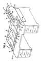
- Figure 1 illustrates an envelope sorting apparatus 1 in operational association with a mail extraction desk 2.
- the sorting apparatus 1 has been shown in use in combination with a "Rapid Extraction Desk" of the type manufactured by the Opex Corporation of Cherry Hill, New Jersey.
- a "Rapid Extraction Desk" of the type manufactured by the Opex Corporation of Cherry Hill, New Jersey.
- Such a combination of operational elements has been selected to facilitate description of the sorting apparatus 1 of the present invention, however, it is to be understood that the sorting apparatus 1 of the present invention is also capable of use in connection with any of a variety of mail extraction devices which are currently available.
- a sorting apparatus 1 in accordance with the present invention need not be directly associated with a mail extraction device, but may alternatively be used as a stand alone unit.
- the sorting apparatus 1 is positioned in alignment with and over the initial staging area 3 of the mail extraction desk 2. Accordingly, envelopes will be sequentially delivered to the initial staging area 3 in accordance with opertion of the sorting apparatus 1, enabling a pre-sorting of envelopes delivered to the mail extraction desk 2 as will be described below.
- an envelope to be processed is first severed along a lateral edge by an edge cutting device 4, whereupon the envelope is drawn along a linear path which traverses the mail extraction desk 2 by means of an appropriate .conveyor 5.
- Conveyor 5 first delivers a staged envelope past a second edge cutting device 6, which severs the top edge of the envelope to prepare the envelope for delivery to an-extraction staging area 7.
- suction cups 8 appropriately engage the staged envelope, spreading apart the sides of the envelope to reveal the contents. The contents are then capable of being removed from the envelope and sorted as desired, making use of the trays 9 and bins 10 associated with the mail extraction desk 2.
- the sorting apparatus 1 is positioned on the mail extraction desk 2 so that the discharge 13 of the sorting apparatus 1 is in communication with the initial staging area 3 of the mail extraction desk 2.
- a series of envelopes 14-to be sorted, opened and emptied are then placed in the sorting apparatus 1, as distinguished from the mail extraction desk, for sorting prior to opening and extraction.
- a plurality of envelopes l4 are capable of being placed within the bin 15 which forms upper portions of the sorting apparatus 1, and that such envelopes 14 are preferably positioned in the bin 15 in a staggered or shingled fashion as illustrated, resting upon a pusher 16.
- Pusher 16 operates in combination with edge stop 17 to retain the series of envelopes 14 in desired orientation.
- the bin 15 of the sorting apparatus 1 is capable of receiving envelopes of different sizes and shapes. Accordingly, as will become apparent from the description which follows, the series of envelopes 14 may be non-uniform in configuration provided the mail extraction desk used is capable of processing non-uniform envelopes. Otherwise, it will be necessary to make sure that the envelopes 14 are of uniform configuration to accommodate the limitations of the mail extraction desk.
- the mail sorting apparatus 1 generally comprises a housing 18 defined by a pair of sides 19 which, in combination with the base 20 of the apparatus and a table 21 for receiving the series of envelopes 14 as previously described, combine to develop an enclosure 22 for receiving segregated envelopes as will be described more fully below.
- the enclosure 22 is secured against unauthorized entry by means of a rear door 23 which is provided with a locking mechanism 24 (see Figure 5).
- a door 23 may be provided which does not incorporate a lock, or in the alternative, the rear or sides of the apparatus may be left open.
- the table 21 which forms upper portions of the enclosure 22 acts in combination with the sides 19 of the sorting apparatus 1 to define the bin 15 which is used to receive the series of envelopes 14-as previously described.
- the table 21 further incorporates a pair of driven chains 25 which, in association with pusher 16, serve to urge the series of envelopes 14 toward the front of the sorting apparatus 1 so as to urge a first envelope 2 0 ' in the series 14 against the stop 17 provided at the end of the table 21, thus readying.the envelope 26 for subsequent operations as follows.
- Pick-up mechanism 27 generally comprises an arm 28, one end of which is provided with a suction cup 29, and the other end of which is pivoted for rotation about a pivot pin 30 responsive to a connecting rod 31 which is operatively connected to a drive mechanism 32.
- the arm 28 of the pick-up mechanism 27 also serves as a means for applying vacuum to the suction cup 29, via an appropriate vacuum hose.
- the drive mechanism 32 is vacuum actuated so that the source of vacuum which operates the drive mechanism 32 is also. available to apply a vacuum at suction cup 29, thereby facilitating operations.
- suction cup 29 is capable of being extended through an aperture 33 in a facing plate 34 which forms part of the front of the sorting apparatus 1, to address the series of envelopes 14. Accordingly, upon appropriate signaling, operation of the drive mechanism 32 is used to pivot the arm 28 about the pivot pin 3U to advance the suction cup 29 through the aperture 33 and into engagement with the first envelope 26 in the series of envelopes 14 provided. Such movement is capable of adjustment by means of the threaded connector 35 of the connecting rod 31.
- the arm 28 is then retracted so as to withdraw the suction cup 29 through the aperture 33, placing the envelope 26 in contact with the facing plate 34, as illustrated in phantom in Figure 3. In this manner, the envelope 26 is placed in proper positioning for sorting as follows.
- Sensing means 37 generally comprises a series of drive wheels 38 in operational association with a roller/follower 39.
- a plurality of drive wheels 38 extend through a series of apertures 40 in the facing plate 34 and are commonly connected by a drive shaft 41 which is journalled for rotation in fixed relation to the facing plate 34, and which is capable of selective rotation by motor 42. via drive belt 43.
- a series of five drive wheels 38 have been provided at spaced intervals along the drive shaft 41, preferably regularly spaced intervals, to sense the thickness of the envelope 26 at-various locations along its length, and to accommodate envelopes of different lengths. It is to be understood that a greater or lesser number of drive wheels 38 may be used, as desired.
- Roller/follower 39 is preferably continuous and cylindrical, extenting fully across the facing plate 34 and between a pair of follower arms 44. Roller/follower 39 is preferably journaled for rotation between follower arms 44 so that passage of an envelope 26 between the driven wheels 38 and the roller/follower 39 will cause deflection of the follower arms 44 in accordance with the thickness of the envelope 26, and its contents.
- follower arms 44 are pivotally associated with the sorting apparatus, at 43, so that deflection of the roller/follower 39 will cause the follower arms 44 to rotate against a spring and about the pivot 43, in turn rotating a lever 46 which is connected to either of the follower arms 44 and which is operatively associated with a microswitch 47 positioned so as to follow movement of the lever 46.
- an envelope 26 passing between the driven wheels 38 and the roller/follower 39 of the sorting apparatus 1 will cause deflection of the lever 46 in accordance with the thickness of the envelope 26 and its content.
- Such deflection is capable of developing a change in state of the microswitch 47, adjustment of this threshold parameter being achieved by adjusting the location of the microswitch 47 with respect to the lever 46, as desired.
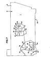
- the envelope 26 will proceed downwardly in Figure 5, passing the sensing means 37 and a guide member 48, eventually contacting a deflector 49 which is positioned beneath the guide member 48 and which is capable of guiding the envelope 26 into the position 50 which is illustrated in phantom in Figure 5.
- the position 50 corresponds to the initial staging area 3 of the mail extraction desk 2, readying the envelope 26 for subequent processing by the mail extraction desk 2 as previously described.
- envelopes having.a thickness which is less than a prescribed threshold value will be passed through the sorting apparatus 1, for subsequent processing at the mail extraction desk 2.
- the deflector 49 is pivoted for rotation about its base 51 in accordance with operation of a connecting rod 52 which connects upper portions 53 of the deflector 49 with the end 54 of a lever mechanism 55.
- Lever mechanism 55 is rotatable about a pivot 56 responsive to interaction between a follower 57 associated with the lever mechanism 55, and a cam 58.
- Cam 58 is rotatable in the direction of the arrow 59 by means of a motor 60, and is provided with a pair of detents 61 which are diametrically opposed to.one another so as to appropriatly time the cam 58.
- a second microswitch 62 is positioned opposite to the follower 57 of the lever mechanism 55 so that the arm 63 of the microswitch 62 will enter one of the detents 61 of the cam 58 as the follower 57 enters the other detent 61.
- Microswitch 62 is used.to discontinue rotation of the cam 58 after a period of time which is sufficient to assure passage of the envelope 26 from between the series of driven wheels 38 and the roller/follower 39, whereupon the deflector 49 is reset and the sorting apparatus 1 is ready to process another envelope.
- the envelope 26 passing between the driven wheels 38 and the roller/follower 39 of the sensing means 37 is caused to enter the enclosure 22 of the mail sorting apparatus 1, rather than passing on to the initial staging area 3 of the mail extraction desk 2.
- envelopes 26 segregated from the series of envelopes 14 being sorted be received in the enclosure 22 in an organized fashion.
- a table 64 is located within the enclosure 22 near the base 20, which table 64 is provided with a driven chain mechanism 65 similar to the driven chain mechanism 25 associated with the table 2l.
- the driven chain mechanism 65 proceeds from the front of the sorting apparatus 1 to its rear.
- a stacker 66 is positioned over the driven chain mechanism 65 so that an envelope 26 passing between the guide member 48 and the facing plate 34 will be received on the angled face 67 of the stacker 66, being assisted in this positioning be a stop 68 formed at the end of the table 64.
- the sorting apparatus 1 be provided with a counter which records the number of envelopes which have been deflected from their normal path of travel and into the enclosure 22. Such a counter may, for example, be operated responsive to microswitch 47. Further, it is preferred that appropriate means be provided for detecting when the stacker 66 has reached the end of its travel, signifying a need to remove contents from the enclosure 22.
- This may be accomplished responsive to a selected number of envelope passings, as detected by means of the counter in association with microswitch 47, or by providing a microswitch or a photocell arrangement at the end of the table 64 which is opposite to the stop 68, to signify the limit in travel of the stacker 66.
- Either sensing scheme may be used to activate a warning light or buzzer to signify the need to empty the enclosure 22 of its contents, if desired.
- sorting apparatus 1 serves well to satisfy each of the objectives previously set forth. It will also be understood that the sorting apparatus 1 previously described is capable of variation without departing from the spirit and scope of the present invention.
- the sorting apparatus 1 of the present invention is also capable of use in combination with any of a number of mail extraction desks apart from the .embodiment illustrated, such as that illustrated in U.S. Patent No. 4,139,977, for example, or in the alternative, as a stand alone unit which is not associated with a mail extraction desk 2 of any kind.
- the sorting apparatus 1 is provided with a photocell 69 ( Figure 5) which is capable of being illuminated by a lamp 70 if the staging area 3 of the mail extraction desk 2 does not contain an envelope.
- This condition is used to activate the drive mechanism 32 which operates the pick-up mechanism 27, initiating the processing of an envelope 26 to be sorted. Otherwise, operation of the pick-up mechanism 27 is inhibited. This or other modifications may be required when interfacing the sorting apparatus 1 with different types of mail extraction equipment.
- appropriate means may be provided to receive envelopes delivered to the position 50 illustrated in Figure 5, such as a simple bin or bag for receiving envelopes, or preferably, a stacking mechanism similar to that illustrated in Figure 7 which is capable of receiving the envelopes in an oriented, shingled fashion.
- the enclosure 22 of a sorting apparatus 1 used either in combination with a mail extraction desk, or as a stand alone unit may be provided with a locking door 23 to provide a secured enclosure 22, or in the alternative, may be provided with either an access door or a simple opening, depending upon whether the envelopes collected in the enclosure 22 are to be accessable to anyone, or only to specif ied operators.
- the parameter sensed in analyzing the series of envelopes 14 is the thickness of the envelopes and their contents. This may be used to isolate relatively thin envelopes from relatively thick envelopes, or vice versa. Such a capability finds application in connection with the segregation of envelopes which are relatively thin, and which are therefore expected to contain only a single invoice and a single payment, for expedited handling. Such a capability also finds application in connection with the segregation of relatively thick envelopes, . which are expected to contain a processed or returned credit card, and which should therefore only be accessable to designated authorized personnel.
- the sorting apparatus of the present invention is not limited to the sensing of envelope thickness by means of a microswitch as previously described.
- sensing of the thickness of the envelope may be accomplished by other implements, such as a linear variable differential transformer, for example.
- sort envelopes by sensing the capacitance of the envelope, or the opacity of the envelope, providing alternative means for determining the content of an envelope and for determining which envelopes are to be separated from the ordinary course of processing.
- the sorting apparatus 1 of the present invention has been described in connection with certain specific applications, it will be understood that the sorting apparatus of the present invention will find applicability in a variety of different applications.
- the sorting apparatus may be used to test envelopes to determine the number of documents in a return mailer, to signify which of two or more different courses of action are to be taken. Return mailers containing coins, tokens or similar items may be separated from the series of envelopes under test, is desired.
- envelopes containing paper clips and staples may be separated out, since such implements may not be compatible with the sorting process, or the mail extraction process.
- metal detection sensors may be used to accomplish the sorting function, as distinguished from the thickness sensing means 37 previously described.
Abstract
Description
- The present invention relates generally to the bulk processing of envelopes, and in particular, to the sorting of envelopes in accordance with specified parameters.
- A variety of organizations customarily receive mail in large quantities and in bulk form. Accordingly, a number of devices have been developed to facilitate the handling of such mail so as to enhance productivity. One such apparatus which has found broad acceptance is the mail extraction apparatus, which is capable of receiving mail in bulk form, and of sequentially opening each envelope to appropriately expose its contents for extraction and sorting by an operator. Examples of such devices may be had with reference to United States Patents Number 4,353,197; 4,110,958; and 3,979,884, which are illustrative of the "Rapid Extraction Desk" which is manufactured by the Opex Corporation of Cherry Hill, New Jersey.
- While mail extraction devices of this type have greatly facilitated the extraction of mail from received envelopes (of both uniform and non-uniform size), the nature of certain operations has given rise to the need to sort incoming mail prior to such opening and extraction. This may include a sorting operation based upon envelope thickness, opacity, labeling or some other characteristic definitive of the contents of the envelope.
- As an example, it is at times important to sort envelopes in accordance with their thickness, based upon an assumed relation between the thickness of the envelope and the nature of the documents which it contains. In some ` applications it may be desirable to isolate relatively thin envelopes based upon the assumption that such envelopes contain a payment on an account which includes a single invoice and check, and which is therefore appropriate for expedited processing, as distinguished from other types of mail which are characteristically contained in envelopes of greater thickness. In other applications it may be desirable to isolate relatively thick envelopes based upon the assumption that such envelopes contain a credit card, and therefore require handling by a special operator to avoid the problems of theft.
- In any event, such sorting operations have tradionally been accomplished by high speed sorting devices which are capable of sorting mail by thickness at rates of speed on the order of thirty thousand envelopes per hour. The sorted envelopes are then transferred to mail extraction devices for opening and sorting. However, since it is not . uncommon to have a single high speed sorting device operate in conjunction with a plurality of mail extraction devices, in view of their relative differential in speed of operation, it has been found that a break-down of the high speed sorting device can create an impediment to the overall extraction operation which can seriously impair the productivity of the mail room as a result.
- Since it has remained desirable to pre-sort mail in connection with a number of mail extraction operations, it therefore remains desirable to develop a sorting device which does not present a potential impediment to the efficiency of the mail extraction operation.
- It is therefore a primary object of the present invention to provide an improved envelope sorting apparatus.
- It is also an object of the present invention to provided a sorting apparatus which is simple in construction. and reliable in use.
- It is also an object of the present invention to provide a sorting apparatus which is capable of operation in conjunction with any of a number of existing mail extraction devices, or as a stand alone unit.
- It is also an object of the present invention to provide a sorting apparatus which is capable of forming an integral part of any of a number of existing mail extraction devices.
- It is also an object of the present invention to provide a sorting apparatus which is capable of forming an integral part of a mail extraction device so as to enable a sorting of mail prior to opening and extraction of the contents.
- It is also an object of the present invention to provide a sorting apparatus which provides the foregoing improvements, and which is capable of efficiently sorting envelopes in accordance with specified characteristics.
- It is also an object of the present invention to provide a sorting apparatus which provides the foregoing improvements, and which is capable of sorting envelopes in an organized fashion.
- It is also an object of the present invention to * provide a sorting apparatus which provides the foregoing improvements, and which is capable of delivering envelopes of specified characteristic to a secured area which can only be accessed by designated personnel.
- These and other objects which will become apparent are achieved in accordance with the present invention by providing a sorting apparatus which sequentially delivers envelopes to a staging area for transfer past means for sensing specified characteristics of each envelope and/or its contents, and which incorporates a deflector mechanism which is capable of selectively delivering envelopes to any of a plurality of receiving areas in accordance with signals received from the sensing means.
- As a stand alone unit, the deflector mechanism is capable of directing an envelope received in the apparatus and analyzed by the sensing means to different areas for subsequent collection and transfer to an appropriate mail extraction device, or to other operations as desired. As an integral portion of a mail extraction device, the deflector mechanism of the sorting apparatus provides a means for sorting mail in accordance with specified characteristics so that an envelope exhibiting the specified characteristic is deflected from the mail extraction device prior to opening, and so that all other envelopes are capable of proceeding from the sorting operation directly to the mail extraction operation. In either embodiment, the area into which envelopes of a specified characteristic are deflected may be secured, if desired, so that the diverted envelopes may be safely retained for subsequent access only by authorized personnel.
- For further detail regarding a preferred embodiment envelope sorting apparatus in accordance with the present invention, reference is made to the detailed description which follows, taken in conjunction with the following illustration.
-
- Figure 1 is an isometric view illustrating an envelope sorting apparatus in accordance with the present invention, in operational association with a mail extraction desk.
- Figure 2 is an enlarged, elevational view'of the envelope sorting apparatus of Figure 1, with portions broken away to show internal constuction detail.
- Figure 3 is a partial sectional view of the envelope staging area of the apparatus illustrated in Figure 2, showing the pick-up arm in its extended position.
- Figure 4 is an end elevational view of the envelope sorting apparatus illustrated in Figure 1, with portions broken away to show internal construction detail.
- Figure 5 is an elevational view similar-to that of Figure 2, illustrating passage of an envelope from the sorting apparatus to the mail extraction desk.
- Figure 6 is a partial sectional view of the region VI shown in Figure 5, showing passage of an envelope through the sensing mechanism.
- Figure 7 is an elevational view similar to that of Figure 2, with portions broken away to illustrate deflection of an envelope of prescribed characteristics into a secured area.
- In the several views provided, like reference numerals denote similar structure.
- Although specific forms of the invention have been selected for illustration in the drawings, and the following description is drawn in specific terms for the purpose of describing these forms of the invention, this description is not intended to limit the scope of the invention which is defined in the appended claims.
- Figure 1 illustrates an
envelope sorting apparatus 1 in operational association with amail extraction desk 2. For the purposes of illustration, thesorting apparatus 1 has been shown in use in combination with a "Rapid Extraction Desk" of the type manufactured by the Opex Corporation of Cherry Hill, New Jersey. Such a combination of operational elements has been selected to facilitate description of thesorting apparatus 1 of the present invention, however, it is to be understood that thesorting apparatus 1 of the present invention is also capable of use in connection with any of a variety of mail extraction devices which are currently available. It will further be understood that asorting apparatus 1 in accordance with the present invention need not be directly associated with a mail extraction device, but may alternatively be used as a stand alone unit. - Before turning to a detailed description of the
envelope sorting apparatus 1, it will be noted that thesorting apparatus 1 is positioned in alignment with and over theinitial staging area 3 of themail extraction desk 2. Accordingly, envelopes will be sequentially delivered to theinitial staging area 3 in accordance with opertion of thesorting apparatus 1, enabling a pre-sorting of envelopes delivered to themail extraction desk 2 as will be described below. - From the
staging area 3, an envelope to be processed is first severed along a lateral edge by an edge cutting device 4, whereupon the envelope is drawn along a linear path which traverses themail extraction desk 2 by means of an appropriate .conveyor 5. Conveyor 5 first delivers a staged envelope past a second edge cutting device 6, which severs the top edge of the envelope to prepare the envelope for delivery to an-extraction staging area 7. Atextraction staging area 7, suction cups 8 appropriately engage the staged envelope, spreading apart the sides of the envelope to reveal the contents. The contents are then capable of being removed from the envelope and sorted as desired, making use of thetrays 9 andbins 10 associated with themail extraction desk 2. Thereafter, the envelope is conveyed past asensor 11 which assures that the envelope has been emptied of all of its contents, whereupon the empty envelope is discarded at 12. In this manner, envelopes delivered to thestaging area 3 are sequentially emptied of their contents and disposed of in an organized fashion. For further detail regarding construction of a mail extraction desk having the forgoing capablities, reference is made to the subject matter of United States Patents Number 4,353,197; 4,110,958; and 3,979,884, which is incorporated by reference as if fully set forth herein. - The
sorting apparatus 1 is positioned on themail extraction desk 2 so that thedischarge 13 of thesorting apparatus 1 is in communication with theinitial staging area 3 of themail extraction desk 2. A series of envelopes 14-to be sorted, opened and emptied are then placed in thesorting apparatus 1, as distinguished from the mail extraction desk, for sorting prior to opening and extraction. With reference to Figure 2, it will be seen that a plurality of envelopes l4 are capable of being placed within thebin 15 which forms upper portions of thesorting apparatus 1, and thatsuch envelopes 14 are preferably positioned in thebin 15 in a staggered or shingled fashion as illustrated, resting upon apusher 16. Pusher 16 operates in combination withedge stop 17 to retain the series ofenvelopes 14 in desired orientation. Thebin 15 of thesorting apparatus 1 is capable of receiving envelopes of different sizes and shapes. Accordingly, as will become apparent from the description which follows, the series ofenvelopes 14 may be non-uniform in configuration provided the mail extraction desk used is capable of processing non-uniform envelopes. Otherwise, it will be necessary to make sure that theenvelopes 14 are of uniform configuration to accommodate the limitations of the mail extraction desk. - The
mail sorting apparatus 1 generally comprises ahousing 18 defined by a pair ofsides 19 which, in combination with thebase 20 of the apparatus and a table 21 for receiving the series ofenvelopes 14 as previously described, combine to develop anenclosure 22 for receiving segregated envelopes as will be described more fully below. In the embodiment illustrated, theenclosure 22 is secured against unauthorized entry by means of arear door 23 which is provided with a locking mechanism 24 (see Figure 5). Of course, in the event that a securedenclosure 22 is not desired or necessary, adoor 23 may be provided which does not incorporate a lock, or in the alternative, the rear or sides of the apparatus may be left open. - The table 21 which forms upper portions of the
enclosure 22 acts in combination with thesides 19 of thesorting apparatus 1 to define thebin 15 which is used to receive the series of envelopes 14-as previously described. The table 21 further incorporates a pair of drivenchains 25 which, in association withpusher 16, serve to urge the series ofenvelopes 14 toward the front of thesorting apparatus 1 so as to urge a first envelope 20' in theseries 14 against thestop 17 provided at the end of the table 21, thus readying.theenvelope 26 for subsequent operations as follows. - Positioned in forward portions of the
sorting apparatus 1 is an envelope pick-upmechanism 27. Pick-upmechanism 27 generally comprises anarm 28, one end of which is provided with asuction cup 29, and the other end of which is pivoted for rotation about apivot pin 30 responsive to a connectingrod 31 which is operatively connected to adrive mechanism 32. Thearm 28 of the pick-upmechanism 27 also serves as a means for applying vacuum to thesuction cup 29, via an appropriate vacuum hose. In its preferred embodiment, thedrive mechanism 32 is vacuum actuated so that the source of vacuum which operates thedrive mechanism 32 is also. available to apply a vacuum atsuction cup 29, thereby facilitating operations. - Referring to Figures 2 and 3, it will be seen that
suction cup 29 is capable of being extended through anaperture 33 in a facingplate 34 which forms part of the front of thesorting apparatus 1, to address the series ofenvelopes 14. Accordingly, upon appropriate signaling, operation of thedrive mechanism 32 is used to pivot thearm 28 about the pivot pin 3U to advance thesuction cup 29 through theaperture 33 and into engagement with thefirst envelope 26 in the series ofenvelopes 14 provided. Such movement is capable of adjustment by means of the threadedconnector 35 of the connectingrod 31. Upon engaging theenvelope 26, and applying a vacuum atsuction cup 29; thearm 28 is then retracted so as to withdraw thesuction cup 29 through theaperture 33, placing theenvelope 26 in contact with the facingplate 34, as illustrated in phantom in Figure 3. In this manner, theenvelope 26 is placed in proper positioning for sorting as follows. - With reference to Figures 3 and 4, an
envelope 26 brought into contact with facingplate 34 will drop through apassageway 36 developed between the end of the table 21 and the facingplate 34 so as to enable theenvelope 26 to address means 37 for sensing the thickness of the envelope 26 (and its contents). Sensing means 37 generally comprises a series ofdrive wheels 38 in operational association with a roller/follower 39. - In the embodiment illustrated, a plurality of
drive wheels 38 extend through a series ofapertures 40 in the facingplate 34 and are commonly connected by adrive shaft 41 which is journalled for rotation in fixed relation to the facingplate 34, and which is capable of selective rotation bymotor 42. viadrive belt 43. It will be noted that a series of fivedrive wheels 38 have been provided at spaced intervals along thedrive shaft 41, preferably regularly spaced intervals, to sense the thickness of theenvelope 26 at-various locations along its length, and to accommodate envelopes of different lengths. It is to be understood that a greater or lesser number ofdrive wheels 38 may be used, as desired. - Roller/
follower 39 is preferably continuous and cylindrical, extenting fully across the facingplate 34 and between a pair offollower arms 44. Roller/follower 39 is preferably journaled for rotation betweenfollower arms 44 so that passage of anenvelope 26 between the drivenwheels 38 and the roller/follower 39 will cause deflection of thefollower arms 44 in accordance with the thickness of theenvelope 26, and its contents. To this end,follower arms 44 are pivotally associated with the sorting apparatus, at 43, so that deflection of the roller/follower 39 will cause thefollower arms 44 to rotate against a spring and about thepivot 43, in turn rotating alever 46 which is connected to either of thefollower arms 44 and which is operatively associated with amicroswitch 47 positioned so as to follow movement of thelever 46. In this manner, and with reference to Figure 6; anenvelope 26 passing between the drivenwheels 38 and the roller/follower 39 of thesorting apparatus 1 will cause deflection of thelever 46 in accordance with the thickness of theenvelope 26 and its content. Such deflection is capable of developing a change in state of themicroswitch 47, adjustment of this threshold parameter being achieved by adjusting the location of themicroswitch 47 with respect to thelever 46, as desired. - In the event that the thickness of the
envelope 26, with its contents, is insufficient to cause a deflection in roller/follower 39 which will cause a change in state of themicroswitch 47, theenvelope 26 will proceed downwardly in Figure 5, passing the sensing means 37 and aguide member 48, eventually contacting adeflector 49 which is positioned beneath theguide member 48 and which is capable of guiding theenvelope 26 into theposition 50 which is illustrated in phantom in Figure 5. In the embodiment: illustrated in the drawings, theposition 50 corresponds to theinitial staging area 3 of themail extraction desk 2, readying theenvelope 26 for subequent processing by themail extraction desk 2 as previously described. Thus, envelopes having.a thickness which is less than a prescribed threshold value will be passed through thesorting apparatus 1, for subsequent processing at themail extraction desk 2. - In the event that the
envelope 26, together with its contents, is of a thickness which exceeds the selected threshold value, deflection of the roller/follower 39 (Figure 6) will cause thefollower arms 44 to rotate about thepivot 43 such that thelever 46 will cause themicroswitch 47 to change state. This change in state is used to signify the-need for special handling of theenvelope 26 being processed, as followsj - The
deflector 49 is pivoted for rotation about itsbase 51 in accordance with operation of a connectingrod 52 which connectsupper portions 53 of thedeflector 49 with theend 54 of alever mechanism 55.Lever mechanism 55 is rotatable about apivot 56 responsive to interaction between afollower 57 associated with thelever mechanism 55, and acam 58.Cam 58 is rotatable in the direction of thearrow 59 by means of amotor 60, and is provided with a pair ofdetents 61 which are diametrically opposed to.one another so as to appropriatly time thecam 58. As illustrated in Figure 5, when thefollower 57 of thelever mechanism 55 rest within adetent 61 of thecam 58, thedeflector 49 is positioned beneath theguide member 48, to deliver envelopes to theinitial staging area 3 of themail extraction desk 2 as previously described. However, rotation of thecam 58 will cause thefollower 57 of thelever mechanism 55 to be drawn out of thedetent 61, in tu.rn urging thedeflector 49 into a position beneath the facingplate 34, as illustrated in Figure 7. Accordingly, rotation of thecam 58 responsive to changes in state of themicroswitch 47 will cause a corresponding change in state of thedeflector 49 from the orientation illustrated in Figure 5 to the orientation illustrated in Figure 7. - A
second microswitch 62 is positioned opposite to thefollower 57 of thelever mechanism 55 so that thearm 63 of themicroswitch 62 will enter one of thedetents 61 of thecam 58 as thefollower 57 enters theother detent 61.Microswitch 62 is used.to discontinue rotation of thecam 58 after a period of time which is sufficient to assure passage of theenvelope 26 from between the series of drivenwheels 38 and the roller/follower 39, whereupon thedeflector 49 is reset and thesorting apparatus 1 is ready to process another envelope. - Accordingly, as a result of the change in state sensed at
microswitch 47, theenvelope 26 passing between the drivenwheels 38 and the roller/follower 39 of the sensing means 37 is caused to enter theenclosure 22 of themail sorting apparatus 1, rather than passing on to theinitial staging area 3 of themail extraction desk 2. If desired, it is possible to merely allow segregated envelopes to collect within theenclosure 22 for subsequent retrieval as desired. However, it is preferred thatenvelopes 26 segregated from the series ofenvelopes 14 being sorted be received in theenclosure 22 in an organized fashion. To this end, a table 64 is located within theenclosure 22 near thebase 20, which table 64 is provided with a drivenchain mechanism 65 similar to the drivenchain mechanism 25 associated with the table 2l. However, as distinguished from the drivenchain mechanism 25, the drivenchain mechanism 65 proceeds from the front of thesorting apparatus 1 to its rear. Astacker 66 is positioned over the drivenchain mechanism 65 so that anenvelope 26 passing between theguide member 48 and the facingplate 34 will be received on theangled face 67 of thestacker 66, being assisted in this positioning be astop 68 formed at the end of the table 64. By appropriately advancing (e.g., responsive to microswitch 47) the drivenchain mechanism 65 each time an envelope is to be received on thestacker 66, a series of staggered or shingled envelopes is developed within theenclosure 22, for subsequent retrieval as appropriate. - , Since the envelopes received within the
enclosure 22 will by and large be hidden from view, and as a security measure, it is preferred that thesorting apparatus 1 be provided with a counter which records the number of envelopes which have been deflected from their normal path of travel and into theenclosure 22. Such a counter may, for example, be operated responsive tomicroswitch 47. Further, it is preferred that appropriate means be provided for detecting when thestacker 66 has reached the end of its travel, signifying a need to remove contents from theenclosure 22. This may be accomplished responsive to a selected number of envelope passings, as detected by means of the counter in association withmicroswitch 47, or by providing a microswitch or a photocell arrangement at the end of the table 64 which is opposite to thestop 68, to signify the limit in travel of thestacker 66. Either sensing scheme may be used to activate a warning light or buzzer to signify the need to empty theenclosure 22 of its contents, if desired. - It will therefore be seen that the
sorting apparatus 1 serves well to satisfy each of the objectives previously set forth. It will also be understood that thesorting apparatus 1 previously described is capable of variation without departing from the spirit and scope of the present invention. - For example, the foregoing description discusses a
mail sorting apparatus 1 in operational association-with the "Rapid Extraction Desk" of the Opex Corporation. However, it will be understood that thesorting apparatus 1 of the present invention is also capable of use in combination with any of a number of mail extraction desks apart from the .embodiment illustrated, such as that illustrated in U.S. Patent No. 4,139,977, for example, or in the alternative, as a stand alone unit which is not associated with amail extraction desk 2 of any kind. - If used in combination with a mail extraction desk, certain physical modifications will generally be required to integrate the
sorting apparatus 1 with the mail extraction desk used. This may include modifications in overall size and configuration. This may also include appropriate interfacing with the operating mechanism of the mail extraction desk used. For example, in connection with themail extraction desk 2 illustrated in the drawings, it is conceivable that absent appropriate regulation, an envelope could be discharged from thesorting apparatus 1 before a previous envelope, staged at 3, is processed through themail extraction desk 2. To prevent such an occurence, thesorting apparatus 1 is provided with a photocell 69 (Figure 5) which is capable of being illuminated by alamp 70 if thestaging area 3 of themail extraction desk 2 does not contain an envelope. This condition is used to activate thedrive mechanism 32 which operates the pick-upmechanism 27, initiating the processing of anenvelope 26 to be sorted. Otherwise, operation of the pick-upmechanism 27 is inhibited. This or other modifications may be required when interfacing thesorting apparatus 1 with different types of mail extraction equipment. - If used as a stand alone unit, appropriate means may be provided to receive envelopes delivered to the
position 50 illustrated in Figure 5, such as a simple bin or bag for receiving envelopes, or preferably, a stacking mechanism similar to that illustrated in Figure 7 which is capable of receiving the envelopes in an oriented, shingled fashion. - As indicated previously, the
enclosure 22 of asorting apparatus 1 used either in combination with a mail extraction desk, or as a stand alone unit, may be provided with a lockingdoor 23 to provide asecured enclosure 22, or in the alternative, may be provided with either an access door or a simple opening, depending upon whether the envelopes collected in theenclosure 22 are to be accessable to anyone, or only to specif ied operators. - In connection with the foregoing discussion, the parameter sensed in analyzing the series of
envelopes 14 is the thickness of the envelopes and their contents. This may be used to isolate relatively thin envelopes from relatively thick envelopes, or vice versa. Such a capability finds application in connection with the segregation of envelopes which are relatively thin, and which are therefore expected to contain only a single invoice and a single payment, for expedited handling. Such a capability also finds application in connection with the segregation of relatively thick envelopes, . which are expected to contain a processed or returned credit card, and which should therefore only be accessable to designated authorized personnel. - However, the sorting apparatus of the present invention is not limited to the sensing of envelope thickness by means of a microswitch as previously described. Alternatively, sensing of the thickness of the envelope may be accomplished by other implements, such as a linear variable differential transformer, for example. It is also possible to sort envelopes by sensing the capacitance of the envelope, or the opacity of the envelope, providing alternative means for determining the content of an envelope and for determining which envelopes are to be separated from the ordinary course of processing.
- Although the
sorting apparatus 1 of the present invention has been described in connection with certain specific applications, it will be understood that the sorting apparatus of the present invention will find applicability in a variety of different applications. For example, apart from sensing relatively thin envelopes containing a single invoice and payment, or relatively thick envelopes containing a credit card, the sorting apparatus may be used to test envelopes to determine the number of documents in a return mailer, to signify which of two or more different courses of action are to be taken. Return mailers containing coins, tokens or similar items may be separated from the series of envelopes under test, is desired. In a related application., envelopes containing paper clips and staples may be separated out, since such implements may not be compatible with the sorting process, or the mail extraction process. In the event that the implement involved is metallic, it will be understood that metal detection sensors may be used to accomplish the sorting function, as distinguished from the thickness sensing means 37 previously described. - Lastly, although the foregoing description primarily addresses means for sensing the content of an envelope based upon characteristics of the materials which the envelope contains, it is equally possible to achieve sorting responsive to markings or symbols provided on the outside of the envelope, such as magnetic markings, bar codes, or the like. Of course, in such case appropriate means for sensing such indicia would be substituted for the sensing means 37 described above.
- It will therefore be understood.that various changes in the details, materials and arrangement of parts which have been herein described and illustrated in order to explain the nature of this invention may be made by those skilled in the art within the principle and scope of the invention-as expressed in the following claims.
Claims (19)
Applications Claiming Priority (2)
| Application Number | Priority Date | Filing Date | Title |
|---|---|---|---|
| US63095584A | 1984-07-16 | 1984-07-16 | |
| US630955 | 1984-07-16 |
Publications (2)
| Publication Number | Publication Date |
|---|---|
| EP0169145A2 true EP0169145A2 (en) | 1986-01-22 |
| EP0169145A3 EP0169145A3 (en) | 1986-07-30 |
Family
ID=24529245
Family Applications (1)
| Application Number | Title | Priority Date | Filing Date |
|---|---|---|---|
| EP85401460A Withdrawn EP0169145A3 (en) | 1984-07-16 | 1985-07-16 | Envelope sorting apparatus |
Country Status (4)
| Country | Link |
|---|---|
| EP (1) | EP0169145A3 (en) |
| AU (1) | AU4506185A (en) |
| ES (1) | ES8703302A1 (en) |
| ZA (1) | ZA855343B (en) |
Cited By (8)
| Publication number | Priority date | Publication date | Assignee | Title |
|---|---|---|---|---|
| EP0225288A2 (en) * | 1985-11-27 | 1987-06-10 | Opex Corporation | Apparatus for monitoring the thickness of an object |
| WO1988001543A1 (en) * | 1986-09-05 | 1988-03-10 | Opex Corporation | Apparatus for the automated processing of bulk mail and the like |
| WO1994004378A1 (en) * | 1992-08-19 | 1994-03-03 | The Technology Partnership Plc | Apparatus and method for checking an envelope for contents |
| US5310062A (en) * | 1986-09-05 | 1994-05-10 | Opex Corporation | Apparatus for automated mail extraction and remittance processing |
| EP0605065A1 (en) * | 1992-12-31 | 1994-07-06 | Hadewe B.V. | Method and apparatus for verifying whether documents have been separated from an opened envelope |
| US5397003A (en) * | 1986-09-05 | 1995-03-14 | Opex Corporation | Method and apparatus for determining the orientation of a document |
| US5460273A (en) * | 1986-09-05 | 1995-10-24 | Opex Corporation | Apparatus for the automated processing of bulk mail having varied characteristics |
| US5842693A (en) * | 1986-09-05 | 1998-12-01 | Opex Corporation | Automated mail extraction and remittance processing |
Citations (2)
| Publication number | Priority date | Publication date | Assignee | Title |
|---|---|---|---|---|
| US3712468A (en) * | 1971-02-24 | 1973-01-23 | W Wenner | Device which scans and detects for contents in a package |
| US4272943A (en) * | 1977-05-31 | 1981-06-16 | Mail-Ex Corporation | Envelope processing machine and method |
-
1985
- 1985-07-16 ES ES545626A patent/ES8703302A1/en not_active Expired
- 1985-07-16 ZA ZA855343A patent/ZA855343B/en unknown
- 1985-07-16 AU AU45061/85A patent/AU4506185A/en not_active Abandoned
- 1985-07-16 EP EP85401460A patent/EP0169145A3/en not_active Withdrawn
Patent Citations (2)
| Publication number | Priority date | Publication date | Assignee | Title |
|---|---|---|---|---|
| US3712468A (en) * | 1971-02-24 | 1973-01-23 | W Wenner | Device which scans and detects for contents in a package |
| US4272943A (en) * | 1977-05-31 | 1981-06-16 | Mail-Ex Corporation | Envelope processing machine and method |
Cited By (16)
| Publication number | Priority date | Publication date | Assignee | Title |
|---|---|---|---|---|
| EP0225288A3 (en) * | 1985-11-27 | 1988-03-30 | Opex Corporation | Apparatus for monitoring the thickness of an object |
| EP0225288A2 (en) * | 1985-11-27 | 1987-06-10 | Opex Corporation | Apparatus for monitoring the thickness of an object |
| US5540338A (en) * | 1986-09-05 | 1996-07-30 | Opex Corporation | Method and apparatus for determining the orientation of a document |
| WO1988001543A1 (en) * | 1986-09-05 | 1988-03-10 | Opex Corporation | Apparatus for the automated processing of bulk mail and the like |
| US5842693A (en) * | 1986-09-05 | 1998-12-01 | Opex Corporation | Automated mail extraction and remittance processing |
| US5310062A (en) * | 1986-09-05 | 1994-05-10 | Opex Corporation | Apparatus for automated mail extraction and remittance processing |
| US4863037A (en) * | 1986-09-05 | 1989-09-05 | Opex Corporation | Apparatus for the automated processing of bulk mail and the like |
| US5397003A (en) * | 1986-09-05 | 1995-03-14 | Opex Corporation | Method and apparatus for determining the orientation of a document |
| US5439118A (en) * | 1986-09-05 | 1995-08-08 | Opex Corporation | Apparatus for extracting documents from envelopes |
| US5441159A (en) * | 1986-09-05 | 1995-08-15 | Opex Corporation | Apparatus for handling documents for delivery to remittance processing equipment |
| US5460273A (en) * | 1986-09-05 | 1995-10-24 | Opex Corporation | Apparatus for the automated processing of bulk mail having varied characteristics |
| US5518121A (en) * | 1986-09-05 | 1996-05-21 | Opex Corporation | Method for automated mail extraction and remittance processing |
| US5727692A (en) * | 1992-08-19 | 1998-03-17 | Stielow Gmbh & Co. | Apparatus and method for checking an envelope for contents |
| WO1994004378A1 (en) * | 1992-08-19 | 1994-03-03 | The Technology Partnership Plc | Apparatus and method for checking an envelope for contents |
| US5655668A (en) * | 1992-12-27 | 1997-08-12 | Hadewe B.V. | Method and apparatus for verifying whether documents have been separated from an opened envelope |
| EP0605065A1 (en) * | 1992-12-31 | 1994-07-06 | Hadewe B.V. | Method and apparatus for verifying whether documents have been separated from an opened envelope |
Also Published As
| Publication number | Publication date |
|---|---|
| ZA855343B (en) | 1986-02-26 |
| ES8703302A1 (en) | 1987-03-01 |
| ES545626A0 (en) | 1987-03-01 |
| AU4506185A (en) | 1986-01-23 |
| EP0169145A3 (en) | 1986-07-30 |
Similar Documents
| Publication | Publication Date | Title |
|---|---|---|
| US5460273A (en) | Apparatus for the automated processing of bulk mail having varied characteristics | |
| EP0279857B1 (en) | Apparatus for the automated processing of bulk mail and the like | |
| EP0571308B1 (en) | Apparatus and method for automated mail extraction and remittance processing | |
| US5464099A (en) | Method for the automated processing of documents and bulk mail | |
| JPH0236977B2 (en) | ||
| US5924840A (en) | Method of extracting contents from envelopes | |
| US4934892A (en) | Envelope processing apparatus | |
| EP0926634A2 (en) | Coin handling apparatus and a coin deposit machine incorporating such an apparatus | |
| CN101925933B (en) | Coin carrier apparatus and coin handling machine | |
| US6547078B1 (en) | Automated mail extraction and remittance processing | |
| EP0169145A2 (en) | Envelope sorting apparatus | |
| US5538140A (en) | Buffered stacker with drop floor assembly | |
| AU750849B2 (en) | Coin discriminator | |
| JPS6145278B2 (en) | ||
| US4649694A (en) | Envelope contents extraction system | |
| US5842693A (en) | Automated mail extraction and remittance processing | |
| US5348128A (en) | Apparatus for the collection, identification and reclamation of recyclable waste | |
| US5929412A (en) | Method and device for counting cut sheets | |
| JPS62209695A (en) | Recycling type coin teller machine for window service | |
| AU2017101000A4 (en) | A banknote dispenser and banknote sensor arrangement for use with banknotes comprising a transparent portion | |
| KR100514631B1 (en) | A Cash Process System With A Counter & Shunt Winding Function | |
| KR950007839Y1 (en) | Cash arranging apparatus for cash disperser | |
| JPH035969Y2 (en) | ||
| JPS58106673A (en) | Paper money discharger | |
| JPS61127533A (en) | Automatic paper sheet handler |
Legal Events
| Date | Code | Title | Description |
|---|---|---|---|
| PUAI | Public reference made under article 153(3) epc to a published international application that has entered the european phase |
Free format text: ORIGINAL CODE: 0009012 |
|
| AK | Designated contracting states |
Designated state(s): AT BE CH DE FR GB IT LI LU NL SE |
|
| PUAL | Search report despatched |
Free format text: ORIGINAL CODE: 0009013 |
|
| AK | Designated contracting states |
Kind code of ref document: A3 Designated state(s): AT BE CH DE FR GB IT LI LU NL SE |
|
| 17P | Request for examination filed |
Effective date: 19870116 |
|
| 17Q | First examination report despatched |
Effective date: 19880324 |
|
| STAA | Information on the status of an ep patent application or granted ep patent |
Free format text: STATUS: THE APPLICATION IS DEEMED TO BE WITHDRAWN |
|
| 18D | Application deemed to be withdrawn |
Effective date: 19880804 |
|
| RIN1 | Information on inventor provided before grant (corrected) |
Inventor name: STEVENS, ALBERT F. Inventor name: HALEY, PAUL E. |