EP0544194B1 - Method of manufacturing a nail for porous concrete - Google Patents
Method of manufacturing a nail for porous concrete Download PDFInfo
- Publication number
- EP0544194B1 EP0544194B1 EP92119788A EP92119788A EP0544194B1 EP 0544194 B1 EP0544194 B1 EP 0544194B1 EP 92119788 A EP92119788 A EP 92119788A EP 92119788 A EP92119788 A EP 92119788A EP 0544194 B1 EP0544194 B1 EP 0544194B1
- Authority
- EP
- European Patent Office
- Prior art keywords
- nail
- procedure according
- gas concrete
- head
- der
- Prior art date
- Legal status (The legal status is an assumption and is not a legal conclusion. Google has not performed a legal analysis and makes no representation as to the accuracy of the status listed.)
- Expired - Lifetime
Links
- 238000004519 manufacturing process Methods 0.000 title claims description 5
- 239000002184 metal Substances 0.000 claims abstract description 6
- 238000000034 method Methods 0.000 claims description 7
- 241000587161 Gomphocarpus Species 0.000 claims description 6
- 239000011381 foam concrete Substances 0.000 claims 1
- 239000000463 material Substances 0.000 abstract description 6
- 210000000078 claw Anatomy 0.000 abstract 1
- 241000209035 Ilex Species 0.000 description 1
- 238000004873 anchoring Methods 0.000 description 1
- 208000008918 voyeurism Diseases 0.000 description 1
Images

Classifications
-
- F—MECHANICAL ENGINEERING; LIGHTING; HEATING; WEAPONS; BLASTING
- F16—ENGINEERING ELEMENTS AND UNITS; GENERAL MEASURES FOR PRODUCING AND MAINTAINING EFFECTIVE FUNCTIONING OF MACHINES OR INSTALLATIONS; THERMAL INSULATION IN GENERAL
- F16B—DEVICES FOR FASTENING OR SECURING CONSTRUCTIONAL ELEMENTS OR MACHINE PARTS TOGETHER, e.g. NAILS, BOLTS, CIRCLIPS, CLAMPS, CLIPS OR WEDGES; JOINTS OR JOINTING
- F16B15/00—Nails; Staples
- F16B15/04—Nails; Staples with spreading shaft
Definitions
- the invention relates to a method for producing a gas concrete nail consisting of a nail body and a splitting disc.
- a spreading nail which consists of a profile wire.
- This profile wire is kinked in the middle and the sides are laid on top of each other.
- a perforated disc designed as an annular rondelle, holds the shaft together.
- a wedge piece is inserted between the bevels of the tip of the shaft, which pushes into the material between the shaft halves when driving the nail into the material.
- the wedge piece is pressed deep into the material with the effect of these forces, which spread the shaft halves and are intended to anchor them in the material, the spreading effect does not occur, which is a disadvantage of this nail.
- the shortcomings of this nail consist in that, on the one hand, part of the cross-section - that is also the resilience - is lost through the gap (24) of the nail body; on the other hand, the spreading effect occurs only through the tips of the wedged end of the opener, which overrides the spreading effect of the opener if the nail halves slip slightly off the tips.
- the invention has for its object to avoid the disadvantages and to provide a method for producing a gas concrete nail that is easy to carry out and inexpensive.
- the solution of the method is achieved with the characterizing features of claim 1.
- the nail body made of semicircular profile wire is pierced through the splitting disc.
- the crossbar (6) pushes the shaft halves of the nail apart.
- the circular opening with the diameter 0 holds the shaft together at a distance b from the crossbeam. This creates a moment of force that bends the two shaft halves - regardless of the involvement of the surface.
- the radius of the bend is determined by the dimensions a, b, 0 and the material properties of the nail body.
Landscapes
- Engineering & Computer Science (AREA)
- General Engineering & Computer Science (AREA)
- Mechanical Engineering (AREA)
- Joining Of Building Structures In Genera (AREA)
- Filling Or Discharging Of Gas Storage Vessels (AREA)
- Manufacturing Of Tubular Articles Or Embedded Moulded Articles (AREA)
- Curing Cements, Concrete, And Artificial Stone (AREA)
- Reinforcement Elements For Buildings (AREA)
- Forms Removed On Construction Sites Or Auxiliary Members Thereof (AREA)
Abstract
Description
Die Erfindung betrifft ein Verfahren zur Herstellung eines Gasbetonnagels bestehend aus einem Nagelkörper und einer Spaltungsscheibe.The invention relates to a method for producing a gas concrete nail consisting of a nail body and a splitting disc.
Aus DE-A-1625348 ist ein Spreiznagel bekannt, der aus einem Profildraht besteht. Dieser Profildraht ist in der Mitte geknickt und die Seiten sind aufeinander gelegt. Eine gelochte Scheibe als eine ringförmige Rondelle ausgebildet, hält den Schaft zusammen. Zwischen den Abschrägungen der Spitze des Schaftes ist ein Keilstück eingefügt, das sich beim Eintreiben des Nagels ins Material zwischen die Schafthälften drängt. Da aber das Keilstück mit Wirkung dieser Kräfte, die die Schafthälften spreizen und im Material verankern sollen, tief ins Material gedrückt wird, kommt der Spreizungseffekt nicht zustande, was ein Nachteil dieses Nagels darstellt.From DE-A-1625348 a spreading nail is known which consists of a profile wire. This profile wire is kinked in the middle and the sides are laid on top of each other. A perforated disc, designed as an annular rondelle, holds the shaft together. A wedge piece is inserted between the bevels of the tip of the shaft, which pushes into the material between the shaft halves when driving the nail into the material. However, since the wedge piece is pressed deep into the material with the effect of these forces, which spread the shaft halves and are intended to anchor them in the material, the spreading effect does not occur, which is a disadvantage of this nail.
Aus EP-A-0229212 ist ein Gasbetonnagel bekannt, bei dem der Spreizungsteil des Öffners in einem festen Abstand zur Scheibenfläche steht.From EP-A-0229212 a gas concrete nail is known in which the spreading part of the opener is at a fixed distance from the pane surface.
Trotz großer Kompliziertheit bestehen die Mängel dieses Nagels darin, daß zum einen durch den Spalt (24) des Nagelkörpers ein Teil des Querschnitts - also auch der Belastbarkeit - verlorengeht; zum anderen erfolgt der Spreizungseffekt nur durch die Spitzen des gekeilten Endes des Öffners, was bei leichtem Abrutschen der Nagelhälften von den Spitzen den Spreizungseffekt des Öffners außer Kraft setzt.Despite the great complexity, the shortcomings of this nail consist in that, on the one hand, part of the cross-section - that is also the resilience - is lost through the gap (24) of the nail body; on the other hand, the spreading effect occurs only through the tips of the wedged end of the opener, which overrides the spreading effect of the opener if the nail halves slip slightly off the tips.
Der Erfindung liegt die Aufgabe zugrunde, die Nachteile zu vermeinden und ein Verfahren zur Herstellung eines Gasbetonnagels zu schaffen, das einfach durchzuführen und kostengünstig ist.The invention has for its object to avoid the disadvantages and to provide a method for producing a gas concrete nail that is easy to carry out and inexpensive.
Die Lösung des Verfahrens wird mit den kennzeichnenden Merkmalen des Anspruchs 1 erzielt. Der aus halbrundem Profildraht hergestellte Nagelkörper wird durch die Spaltungsscheibe durchgeschlagen. Der Querbalken (6) drückt die Schafthälften des Nagels auseinander. Gleichzeitig hält die kreisförmige Öffnung mit dem Durchmesser 0 den Schaft im Abstand b von dem Querbalken zusammen. Dadurch entsteht ein Kraftmoment, das die beiden Schafthälften - unabhängig von der Mitwirkung des Untergrundes - verbiegt.The solution of the method is achieved with the characterizing features of
Der Radius der Verbiegung wird von den Maßen a, b, 0 und von den Materialeigenschaften des Nagelkörpers bestimmt.The radius of the bend is determined by the dimensions a, b, 0 and the material properties of the nail body.
Weitere vorteilhafte Ausgestaltungen für den Kopf und den Schaft des Gasbetonnagels ergeben sich aus den Unteransprüchen 2-7 und sind auf den Zeichnungen wiedergegeben wie folgt:
- Fig. 1
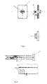
Ein Ausführungsbeispiel des neu entwickelten Gasbetonnagels, wo mit Hilfe des nach den Ansprüchen 1-3 angefertigten Gasbetonnagels auf dem Gasbeton ein Gewindebolzen montiert ist. - Fig. 2
Zeigt die Einzelheiten der Spaltungsscheibe (7) mit dem Querbalken (6) der Breite a, der aus der Fläche der Scheibe auf das Maß b herausgedrückt wird. Die Maße a und b bestimmen die Bieg-Hebel-Wirkung der Spaltungsscheibe und dadurch auch den Radius der Verankerung. - Fig. 3
Hier werden die Merkmale des Nagelkörpers verdeutlicht:- der halbrunde Querschnitt des zur Herstellung des Nagels benutzten Metallstabes
- der Kopf (1) des Nagels
- die Querrillen (2), die die Belastbarkeit des Nagels im Gasbeton wesentlich vergrößern
- die vorteilhafte Ausgestaltung der Spitzen, die die Benutzung des Nagels in Verbindung mit der Spaltungsscheibe erleichtert.
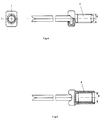
- Fig. 4
Ein mit dem Nagelkörper fest verbundener Gewindebolzen (3), der es ermöglicht in Verbindung mit der Spaltungsscheibe lösbare Befestigungen der Konstruktionsteile an einer Gasbetonwand anzubringen. Der Durchmesser des Gewindes ist nur allgemein mit M-... angegeben. - Fig. 5
Eine mit dem Kopf des Nagels fest verbundene Gewindehülse (4). Die Hülse kann auch bündig mit der Wandfläche montiert werden, was eine lösbare Verbindung mit Hilfe der metrischen Schrauben ergibt. Da auch hier verschiedene Gewindegrößen anwendbar sind, ist das Gewinde nur allgemein mit M-... angegeben. - Fig. 6
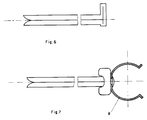
Ein Gasbetonnagel mit in einen Haken geformten Kopf. Der Kopf bleibt beim Hineinschlagen des Nagels in einem bestimmten Abstand von der Wand und ergibt eine Einhängemöglichkeit der Konstruktionsteile. - Fig. 7
Ein Gasbetonnagel mit einer Rohrschelle, die an dem Nagelkopf fest angebracht ist. Die Rohrschelle kann mit Hilfe des Gasbetonnagels in beliebigem Abstand von der Wand angebracht werden, wobei der Nagel nicht ganz in den Gasbeton hineingeschlagen wird. Diese Ausgestaltung ermöglicht die Montage der Rohrleitungen an einer Gasbetonwand.
- Fig. 1
An embodiment of the newly developed gas concrete nail, where a threaded bolt is mounted on the gas concrete using the gas concrete nail manufactured according to claims 1-3. - Fig. 2
Shows the details of the splitting disc (7) with the cross bar (6) of width a, which is pressed out of the surface of the disc to the dimension b. The dimensions a and b determine the bending-lever effect of the splitting disc and thus also the radius of the anchoring. - Fig. 3
Here are the characteristics of the nail body:- the semicircular cross section of the metal rod used to make the nail
- the head (1) of the nail
- the transverse grooves (2), which significantly increase the resilience of the nail in gas concrete
- the advantageous design of the tips, which facilitates the use of the nail in connection with the splitting disc.
- Fig. 4
A threaded bolt (3) firmly connected to the nail body, which enables detachable fastenings of the structural parts to be attached to a gas concrete wall in connection with the splitting disc. The diameter of the thread is only generally indicated with M -.... - Fig. 5
A threaded sleeve (4) firmly connected to the head of the nail. The sleeve can also be mounted flush with the wall surface, which results in a detachable connection using the metric screws. Since different thread sizes can also be used here, the thread is only generally indicated with M -.... - Fig. 6
A gas concrete nail with a head shaped into a hook. The head remains at a certain distance from the wall when the nail is hammered in and provides a way of hanging the structural parts. - Fig. 7
A gas concrete nail with a pipe clamp that is firmly attached to the nail head. The pipe clamp can be attached at any distance from the wall using the gas concrete nail, whereby the nail is not completely hammered into the gas concrete. This configuration enables the pipelines to be mounted on a gas concrete wall.
Claims (7)
- Manufacturing procedure for a nail for foamed concrete consisting of a nail body and a splitting washer; for manufacturing the nail body a half-round metal bar is buckled in the middle with the buckling serving as the nail head and the flat ends being placed on each other so that the tips are showing in different directions; characterized by a metal splitting washer (7) manufactured in a way that two half-round openings (5) in a circle separated from each other by a cross bar (6) are punched out and the cross bar is pressed out of the washer surface so that the given distance b is adjusted.
- Procedure according to claim 1; characterized by the buckling of the metal rod being shaped into a head (1) so that it exhibits a greater surface than the cross section of the nail shank.
- Procedure according to claim 1; characterized by the nail head being closely connected with a bolt (3) furnished with an outer thread.
- Procedure according to claim 1; characterized by the nail head being closely connected with a case (4) furnished with an inner thread.
- Procedure according to claim 1; characterized by a hook-shaped nail head.
- Procedure according to claim 1; characterized by the nail head being closely connected with a pipe clamp (8).
- Procedure according to one of the previous claims; characterized by grooves (2) transverse to the longitudinal axis of the metal rod on both sides.
Applications Claiming Priority (2)
| Application Number | Priority Date | Filing Date | Title |
|---|---|---|---|
| DE4138955A DE4138955C1 (en) | 1991-11-27 | 1991-11-27 | |
| DE4138955 | 1991-11-27 |
Publications (2)
| Publication Number | Publication Date |
|---|---|
| EP0544194A1 EP0544194A1 (en) | 1993-06-02 |
| EP0544194B1 true EP0544194B1 (en) | 1995-08-09 |
Family
ID=6445673
Family Applications (1)
| Application Number | Title | Priority Date | Filing Date |
|---|---|---|---|
| EP92119788A Expired - Lifetime EP0544194B1 (en) | 1991-11-27 | 1992-11-20 | Method of manufacturing a nail for porous concrete |
Country Status (4)
| Country | Link |
|---|---|
| EP (1) | EP0544194B1 (en) |
| AT (1) | ATE126327T1 (en) |
| DE (2) | DE4138955C1 (en) |
| PL (1) | PL296770A1 (en) |
Families Citing this family (3)
| Publication number | Priority date | Publication date | Assignee | Title |
|---|---|---|---|---|
| DE9404499U1 (en) * | 1994-03-17 | 1995-07-20 | Fischer Artur Werke Gmbh | Foldable fastener |
| EP4218635A1 (en) * | 2016-04-20 | 2023-08-02 | Dignity Health | Systems and methods for a pedicle screw assembly |
| DE102019118722B4 (en) * | 2019-07-10 | 2023-06-15 | Obo Bettermann Hungary Kft | impact clamp |
Family Cites Families (21)
| Publication number | Priority date | Publication date | Assignee | Title |
|---|---|---|---|---|
| DE1887C (en) * | J. E. Bennett in Sheffield | Facilities on nails and bolts | ||
| DE132038C (en) * | ||||
| CH83934A (en) * | 1919-05-27 | 1920-02-02 | Jules Bugnon | Nail |
| US1433206A (en) * | 1921-06-22 | 1922-10-24 | Hojnowski Jakob | Expansible spike or nail |
| US2150788A (en) * | 1936-10-05 | 1939-03-14 | Shippee Winsor | Self-clinching nail |
| DE891332C (en) * | 1948-12-09 | 1953-09-28 | Cyrill Ochsner | Calculating machine with rack and pinion drive |
| DE886980C (en) * | 1951-04-20 | 1953-08-20 | Egon Renning | Baseboard nail |
| DE876341C (en) * | 1951-07-14 | 1953-05-11 | Elfriede Lang | Pipe clamp |
| US2745308A (en) * | 1955-03-29 | 1956-05-15 | Gisondi Emanuel | Sheet metal nail having channel shaped, barbed spreading legs |
| CH409529A (en) * | 1959-05-16 | 1966-03-15 | Elastic Ag | Nail and use the same |
| DE1625348A1 (en) * | 1967-09-25 | 1970-06-25 | Moll Gebr Gemofix | Expansion nail |
| DE1775087A1 (en) * | 1968-07-04 | 1971-06-16 | Josef Breuer | Nails, in particular for fastening roofs |
| FR2050373A1 (en) * | 1969-07-29 | 1971-04-02 | Moll Gebr Gemofix | |
| DE2808743A1 (en) * | 1978-03-01 | 1979-09-06 | Guenter Busch | Spreadable fastener for concrete wall - has curved tip to spread points attached to connecting head during driving |
| DE2823372A1 (en) * | 1978-05-29 | 1979-12-06 | Heinrich B Schaefers | SPREAD FASTENERS AND TOOLS AND PROCEDURE FOR PREPARING HOLES FOR SUCH FASTENERS |
| JPS5719449Y2 (en) * | 1980-02-22 | 1982-04-23 | ||
| EP0065556A1 (en) * | 1980-11-28 | 1982-12-01 | KAMPMANN, Helmut | Coupling device for connecting two conduit sections for fluid materials |
| US4533288A (en) * | 1982-07-29 | 1985-08-06 | P.P.M.D. | Drive fastener |
| DE3671073D1 (en) * | 1986-01-16 | 1990-06-13 | Wakai Sangyo Kk | NAIL. |
| DE3838015C1 (en) * | 1988-11-09 | 1990-06-13 | Wakai & Co., Ltd., Higashiosaka, Osaka, Jp | Nail with tube clamp |
| DE8914717U1 (en) * | 1989-12-15 | 1990-02-08 | Tumalski, Tadeusz, 6000 Frankfurt, De |
-
1991
- 1991-11-27 DE DE4138955A patent/DE4138955C1/de not_active Expired - Fee Related
-
1992
- 1992-06-04 DE DE4218435A patent/DE4218435A1/en not_active Ceased
- 1992-11-20 AT AT92119788T patent/ATE126327T1/en not_active IP Right Cessation
- 1992-11-20 EP EP92119788A patent/EP0544194B1/en not_active Expired - Lifetime
- 1992-11-27 PL PL29677092A patent/PL296770A1/en unknown
Also Published As
| Publication number | Publication date |
|---|---|
| PL296770A1 (en) | 1993-07-12 |
| EP0544194A1 (en) | 1993-06-02 |
| DE4218435A1 (en) | 1993-12-09 |
| ATE126327T1 (en) | 1995-08-15 |
| DE4138955C1 (en) | 1993-04-29 |
Similar Documents
| Publication | Publication Date | Title |
|---|---|---|
| EP0574669B1 (en) | Expansion anchor | |
| DE2353055C2 (en) | Plastic fastening element | |
| DE3526940A1 (en) | ANCHOR TO CONCRETE IN HEAVY LOADS | |
| DE2135333C3 (en) | Hammer-in expansion anchor for anchoring in a drill hole in reinforced concrete | |
| EP0261215A1 (en) | Snap hook, especially for mountain climbers | |
| EP0544194B1 (en) | Method of manufacturing a nail for porous concrete | |
| EP0145886B1 (en) | Expanding nail | |
| DE2834009C2 (en) | Device for connecting the ends of two pipes or the like. with a screwless band clamp | |
| DE4112618C2 (en) | ||
| DE3144803C1 (en) | Pipe clip for fastening a floor heating pipe to an insulating layer | |
| DE2654004A1 (en) | ANCHORS FOR ATTACHING OBJECTS TO WALLS, CEILINGS, ETC. | |
| DE2846068A1 (en) | FASTENING DEVICE FOR TUBES OR THE LIKE OBJECTS | |
| DE102006062411A1 (en) | Transportation anchor for double shelled wall or/and covering component, has loop comprising two strands that are spread under formation of straight side pieces, where slotted hole openings are crossed by strands | |
| DE2343713B1 (en) | Suspension device, especially for a false ceiling | |
| EP2426257A1 (en) | Expansion insert for rail nail | |
| CH713432A2 (en) | A method of connecting a spacer rod to a terminal iron on a subcomponent, and a wedge, a spacer and stop bracket assembly and a holder. | |
| DE4310022A1 (en) | Anchor point for prefab. concrete components - is made from single section of reinforcement bar which incorporates shaped lower section and formed or upset lifting head. | |
| DE10011552B4 (en) | Fastening system, for fastening cables to a building wall | |
| DE3200595A1 (en) | Hook element for the roadway support system in mining and tunnelling | |
| EP0058709A1 (en) | Anchoring bolt | |
| DE3305124C2 (en) | ||
| DE19710758C2 (en) | Expandable route laying system for lines and pipes | |
| DE2712410C3 (en) | Device for hanging up false ceilings | |
| EP3693522A1 (en) | System for increasing the wear resistance of anchoring devices and a method for increasing the wear resistance of anchoring devices | |
| DE102005002899B4 (en) | Dorn nail structure |
Legal Events
| Date | Code | Title | Description |
|---|---|---|---|
| PUAI | Public reference made under article 153(3) epc to a published international application that has entered the european phase |
Free format text: ORIGINAL CODE: 0009012 |
|
| AK | Designated contracting states |
Kind code of ref document: A1 Designated state(s): AT BE CH DE DK ES FR GB GR IE IT LI LU MC SE |
|
| RBV | Designated contracting states (corrected) |
Designated state(s): AT DK FR GB SE |
|
| REG | Reference to a national code |
Ref country code: DE Ref legal event code: 8566 |
|
| 17P | Request for examination filed |
Effective date: 19931123 |
|
| 17Q | First examination report despatched |
Effective date: 19940624 |
|
| GRAA | (expected) grant |
Free format text: ORIGINAL CODE: 0009210 |
|
| AK | Designated contracting states |
Kind code of ref document: B1 Designated state(s): AT DK FR GB SE |
|
| PG25 | Lapsed in a contracting state [announced via postgrant information from national office to epo] |
Ref country code: GB Effective date: 19950809 Ref country code: FR Free format text: THE PATENT HAS BEEN ANNULLED BY A DECISION OF A NATIONAL AUTHORITY Effective date: 19950809 Ref country code: DK Effective date: 19950809 |
|
| REF | Corresponds to: |
Ref document number: 126327 Country of ref document: AT Date of ref document: 19950815 Kind code of ref document: T |
|
| PG25 | Lapsed in a contracting state [announced via postgrant information from national office to epo] |
Ref country code: SE Effective date: 19951109 |
|
| PG25 | Lapsed in a contracting state [announced via postgrant information from national office to epo] |
Ref country code: AT Effective date: 19951120 |
|
| EN | Fr: translation not filed | ||
| GBV | Gb: ep patent (uk) treated as always having been void in accordance with gb section 77(7)/1977 [no translation filed] |
Effective date: 19950809 |
|
| PLBE | No opposition filed within time limit |
Free format text: ORIGINAL CODE: 0009261 |
|
| STAA | Information on the status of an ep patent application or granted ep patent |
Free format text: STATUS: NO OPPOSITION FILED WITHIN TIME LIMIT |
|
| 26N | No opposition filed |