DE10011552B4 - Fastening system, for fastening cables to a building wall - Google Patents
Fastening system, for fastening cables to a building wall Download PDFInfo
- Publication number
- DE10011552B4 DE10011552B4 DE2000111552 DE10011552A DE10011552B4 DE 10011552 B4 DE10011552 B4 DE 10011552B4 DE 2000111552 DE2000111552 DE 2000111552 DE 10011552 A DE10011552 A DE 10011552A DE 10011552 B4 DE10011552 B4 DE 10011552B4
- Authority
- DE
- Germany
- Prior art keywords
- holding plate
- nail
- fastening system
- cable
- building wall
- Prior art date
- Legal status (The legal status is an assumption and is not a legal conclusion. Google has not performed a legal analysis and makes no representation as to the accuracy of the status listed.)
- Expired - Fee Related
Links
- 238000007788 roughening Methods 0.000 claims abstract description 6
- 238000009413 insulation Methods 0.000 claims description 3
- 229910000831 Steel Inorganic materials 0.000 claims description 2
- 239000010959 steel Substances 0.000 claims description 2
- 239000004575 stone Substances 0.000 description 7
- 241000587161 Gomphocarpus Species 0.000 description 5
- 239000011505 plaster Substances 0.000 description 4
- 239000004567 concrete Substances 0.000 description 3
- JEIPFZHSYJVQDO-UHFFFAOYSA-N iron(III) oxide Inorganic materials O=[Fe]O[Fe]=O JEIPFZHSYJVQDO-UHFFFAOYSA-N 0.000 description 3
- 239000000463 material Substances 0.000 description 3
- 238000000034 method Methods 0.000 description 3
- 239000000853 adhesive Substances 0.000 description 2
- 230000001070 adhesive effect Effects 0.000 description 2
- 230000015572 biosynthetic process Effects 0.000 description 2
- 239000011455 calcium-silicate brick Substances 0.000 description 2
- 230000006378 damage Effects 0.000 description 2
- 239000004570 mortar (masonry) Substances 0.000 description 2
- 235000008733 Citrus aurantifolia Nutrition 0.000 description 1
- 235000011941 Tilia x europaea Nutrition 0.000 description 1
- 208000027418 Wounds and injury Diseases 0.000 description 1
- 238000004026 adhesive bonding Methods 0.000 description 1
- 238000005452 bending Methods 0.000 description 1
- 238000010276 construction Methods 0.000 description 1
- 238000011161 development Methods 0.000 description 1
- 230000018109 developmental process Effects 0.000 description 1
- 239000000428 dust Substances 0.000 description 1
- 239000013013 elastic material Substances 0.000 description 1
- 238000005516 engineering process Methods 0.000 description 1
- 238000005246 galvanizing Methods 0.000 description 1
- 208000014674 injury Diseases 0.000 description 1
- 238000011900 installation process Methods 0.000 description 1
- 239000004571 lime Substances 0.000 description 1
- 238000004519 manufacturing process Methods 0.000 description 1
- 230000000149 penetrating effect Effects 0.000 description 1
Classifications
-
- H—ELECTRICITY
- H02—GENERATION; CONVERSION OR DISTRIBUTION OF ELECTRIC POWER
- H02G—INSTALLATION OF ELECTRIC CABLES OR LINES, OR OF COMBINED OPTICAL AND ELECTRIC CABLES OR LINES
- H02G3/00—Installations of electric cables or lines or protective tubing therefor in or on buildings, equivalent structures or vehicles
- H02G3/36—Installations of cables or lines in walls, floors or ceilings
Landscapes
- Engineering & Computer Science (AREA)
- Architecture (AREA)
- Civil Engineering (AREA)
- Structural Engineering (AREA)
- Joining Of Building Structures In Genera (AREA)
- Building Environments (AREA)
- Installation Of Indoor Wiring (AREA)
Abstract
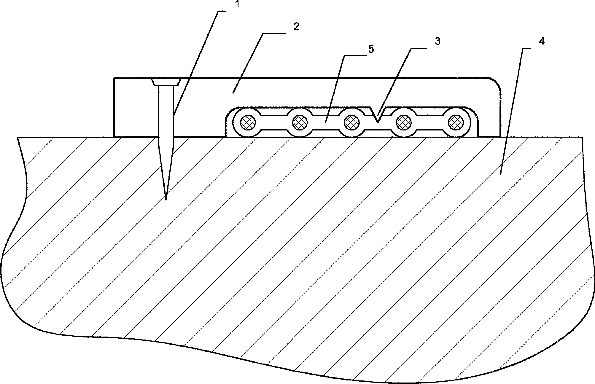
Befestigungssystem zur Befestigung von Kabeln (5) mit einem elastischen Halteplättchen zum Einklemmen des Kabels (5) an einer Gebäudewand (4) oder ähnlichem und einem Nagel (1), welcher in einer Ausnehmung (10) des Haltplättchens aufgenommen ist, dadurch gekennzeichnet, dass der Nagel (1) aus einem Bereich (7) mit gleichbleibendem Durchmesser, dessen Länge in etwa der Stärke des Halteplättchens entspricht und der in der Ausnehmung (10) des Halteplättchens mit engem Sitz geführt ist, und einer daran anschließenden langgezogenen kegeligen Spitze (8) mit aufgerauter Oberfläche (Aufrauung 11) besteht.fastening system for fastening cables (5) with an elastic holding plate for clamping the cable (5) on a building wall (4) or the like and a nail (1) which is in a recess (10) of the holding plate is included, characterized in that the nail (1) an area (7) of constant diameter, the length of which is approximately of strength of the holding plate corresponds to and in the recess (10) of the holding plate run with a tight fit and a subsequent one elongated conical tip (8) with roughened surface (roughening 11) exists.
Description
Die Erfindung betrifft ein Befestigungssystem zur Befestigung von Kabeln an einer Gebäudewand gemäß dem Oberbegriff des Patentanspruchs 1.The The invention relates to a fastening system for fastening cables on a building wall according to the generic term of claim 1.
Aus
der Druckschrift
Aus
der Druckschrift
Aus
der Druckschrift
Aus
der Druckschrift
Aus
der Druckschrift
Aus
der Druckschrift
Insbesondere durch den Einsatz neuer Steintypen (z.B. engmaschige Gittersteine, verschiedene Kalksandsteintypen), aber auch durch neue Bautechnologien (z.B. Verkleben der Steine oder Einsatz von Verzögerungsmörtel) kommt es oft zu großen Problemen bei den bisherigen Befestigungselementen, da die bisher hauptsächlich als Befestigungsgrund genutzte Mauerfuge entfällt, bzw. beim Einsatz von Verzögerungsmörtel nicht genutzt werden kann. Bei den bisherigen Befestigungssystemen besteht ein Nachteil darin, dass durch die Form des Befestigungselementes (Nageltyp, Nagelspitze, Nagellänge) diese beim Aufschlagen auf die Gebäudewand verbogen werden oder z.B. bei Gittersteinen diese die Außenwand durchdringen, jedoch im Kammerraum des Steines keinen Halt finden. Versuche, die Kabel mittels Klebstoffen auf den Gebäudewänden anzubringen sind sehr zeitaufwändig, bei Staub und Feuchtigkeit sogar erfolglos.In particular through the use of new stone types (e.g. close-meshed grid stones, various types of lime sandstone), but also through new construction technologies (e.g. gluing the stones or using delay mortar) there are often major problems in the previous fasteners, since the so far mainly as Wall joint used for fastening is not applicable, or when using Delay mortar does not can be used. With the previous fastening systems a disadvantage in that due to the shape of the fastener (Nail type, nail tip, nail length) these are bent when they hit the building wall or e.g. in the case of lattice blocks, they penetrate the outer wall, however find no hold in the stone's chamber. Try the cables to be attached to the building walls using adhesives are very time consuming, even unsuccessful in dust and moisture.
Der vorliegenden Erfindung liegt die Aufgabe zugrunde, ein Befestigungssystem für eine Befestigung von mindestens einem Kabel an einer Wand zu schaffen, welches bei Ermöglichung einer einfachen Verwendung einen ausreichenden Halt der zu verputzenden Kabel oder Leitungen gewährleistet.The The present invention has for its object a fastening system for one To attach at least one cable to a wall, which if possible a simple use a sufficient hold of the plastered Guaranteed cables or lines.
LÖSUNGSOLUTION
Die Aufgabe der Erfindung wird erfindungsgemäß durch ein Befestigungssystem mit den Merkmalen des unabhängigen Patentanspruchs 1 gelöst.The The object of the invention is achieved by a fastening system with the characteristics of the independent Claim 1 solved.
Erfindungsgemäß besteht der Nagel aus zwei Teilbereichen, nämlich einen Teilbereich mit gleich bleibendem Durchmesser, dessen Länge in etwa der Stärke des Halteplättchens entspricht. Hiermit ist im Bereich des Halteplättchens ein belastbarer Querschnitt gebildet, welcher eine gute Verbindung zwischen Nagel und Halteplättchen gewährleistet und beispielsweise ermöglicht, dass die Ausnehmung in Form einer Bohrung gefertigt ist. Dadurch, dass die Länge des Bereiches mit gleich bleibendem Durchmesser in etwa der Stärke des Halteplättchens entspricht, ist gewährleistet, dass die Länge dieses Teilbereiches der minimal erforderlichen Länge entspricht. Weiterhin ist erfindungsgemäß in der Ausnehmung des Halteplättchens der Nagel mit engem Sitz geführt. Dies hat zur Folge, dass während des Einschlagens des Nagels über das Halteplättchen der Nagel gehalten bzw. geführt werden kann. Hierdurch kann eine Verletzungsgefahr der Finger durch Hammerschläge gemindert werden. Weiterhin ist mit dem Eintritt des Nagels in die Gebäudewand gewährleistet, dass das Halteplättchen in Folge des engen Sitzes exakt ausgerichtet ist, wodurch die Führung des Kabels gut vorgegeben werden kann.According to the invention, the nail consists of two sections, namely a section with a constant diameter, the length of which corresponds approximately to the thickness of the holding plate. A resilient cross-section is hereby formed in the area of the holding plate, which ensures a good connection between the nail and holding plate and, for example, enables the recess to be made in the form of a bore. The fact that the length of the area with a constant diameter corresponds approximately to the thickness of the holding plate ensures that the length of this partial area corresponds to the minimum required length. Furthermore, the nail is guided with a tight fit in the recess of the holding plate. This has the consequence that while driving the nail over the holding plate the nail can be held or guided. This can reduce the risk of injury to the fingers from hammer blows. Furthermore, with the entry of the nail into the wall of the building, it is ensured that the holding plate is exactly aligned due to the tight fit, which means that the cable can be guided well.
An den vorgenannten Teilbereich schließt eine lang gezogene, kegelige Spitze an. Durch diese spezielle Form der Spitze wird insbesondere ein dornförmiges Einkeilen des Nagels in die aus verschiedenen Materialien bestehende Gehäusewand (wie beispielsweise eine Kalksandsteinwand, Gittersteine oder auch Beton) erreicht. Hierbei kann je nach Untergrund die Länge der Spitze verlängert bzw. verkürzt werden. Weiterhin ist erfindungsgemäß die Spitze des Nagels mit einer Aufrauung versehen. Eine derartige Aufrauung kann in einem Teilbereich der Spitze vorgesehen sein oder diese vollständig betreffen. Durch die Aufrauung der Spitze kann ein zusätzliches "Verkrallen" des Nagels mit der Gebäudewand erzielt werden, was den Halt des Nagels und damit des Befestigungssystems gegenüber der Gebäudewand in verschiedenen Steintypen, wie auch in Beton, verbessert.On the aforementioned section includes an elongated, conical Top. This special shape of the tip is particularly a thorn-shaped Wedge the nail into the one made of different materials Housing wall (like e.g. a sand-lime brick wall, lattice stones or concrete) reached. Depending on the surface, the length of the tip can be extended or shortened become. According to the invention, the tip of the nail is also included roughened. Such roughening can be done in one Part of the tip may be provided or affect it completely. The roughening of the tip can cause the nail to "cling" to the building wall be achieved what the hold of the nail and thus the fastening system across from the building wall in various types of stone, as well as in concrete.
Des Weiteren wird erfindungsgemäß eine Beschädigung des Kabels oder der Leitungen durch Hammerschläge ausgeschlossen, da gegenüber herkömmlicher Befestigungssysteme nicht das Befestigungselement (Nagel oder dergleichen) durch das Kabel getrieben wird, sondern das Befestigungssystem erst an der Gebäudewand angebracht wird und nachträglich das Kabel eingeklemmt werden kann.Of According to the invention, damage to the Cable or lines excluded by hammer blows, as compared to conventional Fastening systems not the fastener (nail or the like) is driven by the cable, but the fastening system first on the building wall is attached and subsequently the cable can be pinched.
Nach einem weiteren Vorschlag der Erfindung ist das Haltplättchen als Kunststoffschelle ausgebildet. Derartige Kunststoffschellen sind auf besonders einfache Weise und preiswert zu fertigen. Weiterhin ist der Werkstoff Kunststoff auf einfache Weise mit einer notwendigen Elastizität zu versehen.To Another proposal of the invention is the support plate as Plastic clamp formed. Such plastic clamps are to manufacture in a particularly simple and inexpensive manner. Farther is the plastic material in a simple way with a necessary elasticity to provide.
Vorzugsweise ist der Nagel mit festem Sitz in der Ausnehmung geführt. Dies hat einerseits den Vorteil, dass der Nagel und das Halteplättchen eine Montageeinheit bilden und der Nagel verliersicher vom Halteplättchen geführt ist. Weiterhin kann durch den festen Sitz ein Spiel zwischen Nagel und Halteplättchen ausgeschlossen werden, was eine unerwünschte, nicht exakte Ausrichtung des Halteplättchens gegenüber dem Nagel zur Folge haben könnte.Preferably the nail is firmly seated in the recess. This on the one hand has the advantage that the nail and the holding plate form an assembly unit form and the nail is captively guided by the holding plate. Furthermore, by the a tight fit between nail and holding plate can be excluded, which is an undesirable not exact alignment of the holding plate with respect to Nail could result.
Gemäß einem weiteren erfindungsgemäßen Befestigungssystem ist der Kopf des Nagels vollständig in dem Halteplättchen versenkbar. Hierdurch wird im Bereich des Befestigungssystems eine ebene Oberfläche geschaffen, so dass sich für das Verputzen der Gebäudewand verbesserte Bedingungen ergeben.According to one further fastening system according to the invention the head of the nail is complete in the holding plate retractable. As a result, a flat surface created so that for plastering the building wall result in improved conditions.
Gemäß einer erfindungsgemäßen Weiterbildung des Befestigungssystems weist das Halteplättchen auf der dem Kabel zugewandten Seite eine keilförmige Spitze auf, welche sich in eine Isolierung des Kabels eindrückt. Hierdurch kann zusätzlich zu den elastischen Anpresskräften zwischen Halteplättchen, Kabel und Gebäudewand ein Formschluss zwischen der Spitze des Halteplättchens und dem Kabel hergestellt werden, wodurch die Verbindung zwischen dem Befestigungssystem und dem Kabel gestärkt wird.According to one Training according to the invention of the fastening system has the holding plate on the cable facing Side a wedge-shaped Tip, which is pressed into an insulation of the cable. hereby can additionally to the elastic contact forces between holding plate, cable and building wall a positive connection between the tip of the holding plate and the cable be, whereby the connection between the fastening system and the cable strengthened becomes.
Weiterhin ist es vorteilhaft, wenn der Kopf des Nagels galvanisch verzinkt ist. Hierdurch kann die Ausbildung von Rost vermieden werden.Farther it is advantageous if the head of the nail is galvanized is. As a result, the formation of rust can be avoided.
Vorzugsweise ist das Halteplättchen im Längsschnitt ungefähr U-förmig ausgebildet mit einem Grundschenkel, welcher die Spitze trägt, und zwei Seitenschenkeln, welche das Kabel seitlich einschließen, wobei ein Seitenschenkel die Ausnehmung zur Aufnahme des Nagels bildet und beide Seitenschenkel an der Gebäudewand anliegen. Durch die beiden Seitenschenkel ist eine formschlüssige, seitliche Begrenzung für eine Bewegung der Kabel quer zur Längsachse des Halteplättchens gebildet, wodurch die Befestigung des oder der Kabel an der Gebäudewand sicherer gestaltet werden kann.Preferably is the holding tile in longitudinal section approximately U-shaped formed with one base leg, which carries the tip, and two Side legs, which enclose the cable on the side, whereby a side leg forms the recess for receiving the nail and both side legs lie against the building wall. Through the both side legs is a positive, lateral limitation for one Movement of the cables across the longitudinal axis of the holding plate formed, whereby the attachment of the cable or cables to the building wall can be made safer.
Vorteilhafte Weiterbildungen ergeben sich aus den Unteransprüchen, der Beschreibung und den Zeichnungen.advantageous Further developments result from the subclaims, the description and the Drawings.
KURZBESCHREIBUNG DER FIGURENSUMMARY THE FIGURES
Ein Ausführungsbeispiel der Erfindung ist in der Zeichnung dargestellt und wird im Folgenden näher beschrieben.On embodiment The invention is illustrated in the drawing and is described below described in more detail.
Es zeigen:It demonstrate:
Eine
Kunststoffschelle (
Die
Kunststoffschelle (
Die
in
Der
in
Der
in
Für ein Anbringen
des Befestigungssystems (
Die
Kunststoffschelle (
The plastic clamp (
Durch
neue, erfindungsgemäß ermöglichte Verfahrensweise
ist eine komplett neue und vereinfachte Verlegetechnik möglich. Die
Befestigungssysteme können
in einem Arbeitsgang komplett in entsprechenden Abständen in
der geplanten Kabelverlegetrasse angebracht werden und in einem
weiteren Arbeitsgang wird das Kabel (
- 11
- Nagelnail
- 22
- KunststoffschellePlastic clamp
- 33
- Spitzetop
- 44
- Gebäudewandbuilding wall
- 55
- Kabelelectric wire
- 66
- Nagelkopfnail head
- 77
- BereichArea
- 88th
- Spitzetop
- 99
- Vertiefungdeepening
- 1010
- Ausnehmungrecess
- 1111
- Aufrauungroughening
Claims (12)
Priority Applications (1)
| Application Number | Priority Date | Filing Date | Title |
|---|---|---|---|
| DE2000111552 DE10011552B4 (en) | 2000-03-09 | 2000-03-09 | Fastening system, for fastening cables to a building wall |
Applications Claiming Priority (1)
| Application Number | Priority Date | Filing Date | Title |
|---|---|---|---|
| DE2000111552 DE10011552B4 (en) | 2000-03-09 | 2000-03-09 | Fastening system, for fastening cables to a building wall |
Publications (2)
| Publication Number | Publication Date |
|---|---|
| DE10011552A1 DE10011552A1 (en) | 2001-10-04 |
| DE10011552B4 true DE10011552B4 (en) | 2004-12-09 |
Family
ID=7634134
Family Applications (1)
| Application Number | Title | Priority Date | Filing Date |
|---|---|---|---|
| DE2000111552 Expired - Fee Related DE10011552B4 (en) | 2000-03-09 | 2000-03-09 | Fastening system, for fastening cables to a building wall |
Country Status (1)
| Country | Link |
|---|---|
| DE (1) | DE10011552B4 (en) |
Families Citing this family (2)
| Publication number | Priority date | Publication date | Assignee | Title |
|---|---|---|---|---|
| DE10300447B4 (en) * | 2003-01-07 | 2010-04-08 | AHORN Geräte & Werkzeuge-Vertriebs-GmbH | Composite arrangement of fasteners |
| DE202010004256U1 (en) | 2010-03-26 | 2010-06-10 | Amphenol-Tuchel Electronics Gmbh | Electrical connection element with integrated fastening element |
Citations (6)
| Publication number | Priority date | Publication date | Assignee | Title |
|---|---|---|---|---|
| FR956544A (en) * | 1950-02-02 | |||
| DE849438C (en) * | 1948-04-19 | 1952-09-15 | Ericsson Telefon Ab L M | Fixing nail for electrical lines or the like |
| DE1696736U (en) * | 1954-11-20 | 1955-04-14 | Franz Albert Karbe | NAIL CLAMP FOR ELECTRIC CABLES, ESPECIALLY FLAT CABLES. |
| DE1739058U (en) * | 1956-11-30 | 1957-02-07 | Bettermann Elektro G M B H | ADHESIVE CLAMP FOR FASTENING ELECTRICAL CABLE TO WALLS OR. DGL. |
| DE2907855A1 (en) * | 1979-02-28 | 1980-09-11 | Horst Hollaender | Clamp for locating cables on concrete walls - minimises risk of insulation damage during installation of cable in course of building construction |
| DE29619013U1 (en) * | 1996-11-01 | 1996-12-19 | OBO Bettermann GmbH & Co. KG, 58710 Menden | Device for fastening elements to a surface |
-
2000
- 2000-03-09 DE DE2000111552 patent/DE10011552B4/en not_active Expired - Fee Related
Patent Citations (6)
| Publication number | Priority date | Publication date | Assignee | Title |
|---|---|---|---|---|
| FR956544A (en) * | 1950-02-02 | |||
| DE849438C (en) * | 1948-04-19 | 1952-09-15 | Ericsson Telefon Ab L M | Fixing nail for electrical lines or the like |
| DE1696736U (en) * | 1954-11-20 | 1955-04-14 | Franz Albert Karbe | NAIL CLAMP FOR ELECTRIC CABLES, ESPECIALLY FLAT CABLES. |
| DE1739058U (en) * | 1956-11-30 | 1957-02-07 | Bettermann Elektro G M B H | ADHESIVE CLAMP FOR FASTENING ELECTRICAL CABLE TO WALLS OR. DGL. |
| DE2907855A1 (en) * | 1979-02-28 | 1980-09-11 | Horst Hollaender | Clamp for locating cables on concrete walls - minimises risk of insulation damage during installation of cable in course of building construction |
| DE29619013U1 (en) * | 1996-11-01 | 1996-12-19 | OBO Bettermann GmbH & Co. KG, 58710 Menden | Device for fastening elements to a surface |
Also Published As
| Publication number | Publication date |
|---|---|
| DE10011552A1 (en) | 2001-10-04 |
Similar Documents
| Publication | Publication Date | Title |
|---|---|---|
| EP2348162B1 (en) | Method and device for sealing a separation gap and anchoring seal for a separation joint | |
| EP2148098A2 (en) | Disc-form anchoring element | |
| DE102018101251A1 (en) | Profile rail with plug for attachment to a formwork | |
| DE10011552B4 (en) | Fastening system, for fastening cables to a building wall | |
| DE29517042U1 (en) | Fastening element for fastening insulation boards | |
| EP1541881B1 (en) | Expansion anchor | |
| DE10352084B4 (en) | Fastening element and method for fixing cables | |
| DE19602693A1 (en) | Plaster- or concrete-smoothing cladding for building surface | |
| DE29600810U1 (en) | Fixing element for cables or wires | |
| DE102005000185A1 (en) | Fastening element for fixing insulation boards to a substrate | |
| EP0670429A1 (en) | Fastening element anchored by driving | |
| DE10000059A1 (en) | Fastener for fixing faade elements on walls comprises plate holder with coil shaped part with tubular shaft and two plates and connected to positioning sleeve with openings for guiding through dowel sleeve | |
| DE19523730A1 (en) | Retainer for cables to channel in wall or ceiling | |
| DE4331583A1 (en) | Nail with a spreading area | |
| EP0544194B1 (en) | Method of manufacturing a nail for porous concrete | |
| EP0801234A1 (en) | Expanding anchor, especially for fastening insulating boards on masonry | |
| EP1498651A2 (en) | Fastening device | |
| DE19744115C1 (en) | Fixture device for roof structural components on available installation components | |
| DE19931284C1 (en) | Connector cramp for joining two insulating plates comprises two parallel piercing elements and a bridging element with at least one loop, with the piercing elements beforehand prized outwards to produce a preload | |
| DE29516068U1 (en) | Fastening element, especially for cables | |
| DE202008013358U1 (en) | Overhang strip for a connection plate for buildings | |
| DE9113591U1 (en) | Fastening element for pipe clamps | |
| DE102004036197A1 (en) | Fixing element for fixing cable conduits in milled slots useful for fixing cables and their conduits in wall slots without additional anchoring longitudinal ribs, wedge-, head-, and holding clamps | |
| EP1347182A1 (en) | Expansion dowel | |
| DE29700534U1 (en) | Nail clamp |
Legal Events
| Date | Code | Title | Description |
|---|---|---|---|
| OP8 | Request for examination as to paragraph 44 patent law | ||
| 8364 | No opposition during term of opposition | ||
| 8339 | Ceased/non-payment of the annual fee |