EP2148098A2 - Disc-form anchoring element - Google Patents
Disc-form anchoring element Download PDFInfo
- Publication number
- EP2148098A2 EP2148098A2 EP09163777A EP09163777A EP2148098A2 EP 2148098 A2 EP2148098 A2 EP 2148098A2 EP 09163777 A EP09163777 A EP 09163777A EP 09163777 A EP09163777 A EP 09163777A EP 2148098 A2 EP2148098 A2 EP 2148098A2
- Authority
- EP
- European Patent Office
- Prior art keywords
- anchoring
- anchoring element
- borehole
- shaft
- fastening
- Prior art date
- Legal status (The legal status is an assumption and is not a legal conclusion. Google has not performed a legal analysis and makes no representation as to the accuracy of the status listed.)
- Withdrawn
Links
- 238000004873 anchoring Methods 0.000 title claims abstract description 135
- 238000005452 bending Methods 0.000 claims description 4
- 239000002184 metal Substances 0.000 claims description 4
- 238000000034 method Methods 0.000 claims description 4
- 239000004033 plastic Substances 0.000 claims description 4
- 229920003023 plastic Polymers 0.000 claims description 4
- 238000001746 injection moulding Methods 0.000 claims description 3
- 239000000463 material Substances 0.000 description 10
- 238000003780 insertion Methods 0.000 description 7
- 230000037431 insertion Effects 0.000 description 7
- 238000004140 cleaning Methods 0.000 description 5
- 239000000428 dust Substances 0.000 description 5
- 230000006978 adaptation Effects 0.000 description 3
- 238000005553 drilling Methods 0.000 description 3
- 238000004519 manufacturing process Methods 0.000 description 3
- 229920002430 Fibre-reinforced plastic Polymers 0.000 description 2
- 229910000831 Steel Inorganic materials 0.000 description 2
- 239000012080 ambient air Substances 0.000 description 2
- 239000011151 fibre-reinforced plastic Substances 0.000 description 2
- 239000012811 non-conductive material Substances 0.000 description 2
- 230000002787 reinforcement Effects 0.000 description 2
- 239000010959 steel Substances 0.000 description 2
- 238000004026 adhesive bonding Methods 0.000 description 1
- 230000009286 beneficial effect Effects 0.000 description 1
- 238000011161 development Methods 0.000 description 1
- 230000018109 developmental process Effects 0.000 description 1
- 230000001747 exhibiting effect Effects 0.000 description 1
- 238000002347 injection Methods 0.000 description 1
- 239000007924 injection Substances 0.000 description 1
- 238000009434 installation Methods 0.000 description 1
- 239000000203 mixture Substances 0.000 description 1
- 238000004080 punching Methods 0.000 description 1
- 238000005476 soldering Methods 0.000 description 1
- 239000000243 solution Substances 0.000 description 1
Images
Classifications
-
- F—MECHANICAL ENGINEERING; LIGHTING; HEATING; WEAPONS; BLASTING
- F16—ENGINEERING ELEMENTS AND UNITS; GENERAL MEASURES FOR PRODUCING AND MAINTAINING EFFECTIVE FUNCTIONING OF MACHINES OR INSTALLATIONS; THERMAL INSULATION IN GENERAL
- F16B—DEVICES FOR FASTENING OR SECURING CONSTRUCTIONAL ELEMENTS OR MACHINE PARTS TOGETHER, e.g. NAILS, BOLTS, CIRCLIPS, CLAMPS, CLIPS OR WEDGES; JOINTS OR JOINTING
- F16B13/00—Dowels or other devices fastened in walls or the like by inserting them in holes made therein for that purpose
- F16B13/14—Non-metallic plugs or sleeves; Use of liquid, loose solid or kneadable material therefor
- F16B13/141—Fixing plugs in holes by the use of settable material
-
- F—MECHANICAL ENGINEERING; LIGHTING; HEATING; WEAPONS; BLASTING
- F16—ENGINEERING ELEMENTS AND UNITS; GENERAL MEASURES FOR PRODUCING AND MAINTAINING EFFECTIVE FUNCTIONING OF MACHINES OR INSTALLATIONS; THERMAL INSULATION IN GENERAL
- F16B—DEVICES FOR FASTENING OR SECURING CONSTRUCTIONAL ELEMENTS OR MACHINE PARTS TOGETHER, e.g. NAILS, BOLTS, CIRCLIPS, CLAMPS, CLIPS OR WEDGES; JOINTS OR JOINTING
- F16B13/00—Dowels or other devices fastened in walls or the like by inserting them in holes made therein for that purpose
- F16B13/04—Dowels or other devices fastened in walls or the like by inserting them in holes made therein for that purpose with parts gripping in the hole or behind the reverse side of the wall after inserting from the front
- F16B13/08—Dowels or other devices fastened in walls or the like by inserting them in holes made therein for that purpose with parts gripping in the hole or behind the reverse side of the wall after inserting from the front with separate or non-separate gripping parts moved into their final position in relation to the body of the device without further manual operation
- F16B13/0875—Dowels or other devices fastened in walls or the like by inserting them in holes made therein for that purpose with parts gripping in the hole or behind the reverse side of the wall after inserting from the front with separate or non-separate gripping parts moved into their final position in relation to the body of the device without further manual operation with elastic discs or spring washers anchoring in the hole
-
- F—MECHANICAL ENGINEERING; LIGHTING; HEATING; WEAPONS; BLASTING
- F16—ENGINEERING ELEMENTS AND UNITS; GENERAL MEASURES FOR PRODUCING AND MAINTAINING EFFECTIVE FUNCTIONING OF MACHINES OR INSTALLATIONS; THERMAL INSULATION IN GENERAL
- F16B—DEVICES FOR FASTENING OR SECURING CONSTRUCTIONAL ELEMENTS OR MACHINE PARTS TOGETHER, e.g. NAILS, BOLTS, CIRCLIPS, CLAMPS, CLIPS OR WEDGES; JOINTS OR JOINTING
- F16B43/00—Washers or equivalent devices; Other devices for supporting bolt-heads or nuts
Definitions
- the invention relates to an annular disk-shaped anchoring element for arrangement on a shaft provided with an external profiling of a fastening element with a passage opening for the shaft. Furthermore, the invention relates to a fastenable by means of a curable material in a wellbore fastener having at least one annular disk-shaped anchoring element, and a fastening arrangement with such a fastener.
- fastening element is for example a threaded rod, which is provided over its entire longitudinal extent with a thread as external profiling.
- the adhesion of the hardened mass to the borehole wall and thus the anchoring of the fastening element in the borehole can be improved.
- the cleaning of the borehole represents an additional workload, which also requires for a beneficial result separate tools that are not always available to the user.
- the fastener is called Whole, ie introduced with the anchoring elements arranged on the shaft, in the borehole.
- the annular disk-shaped anchoring elements provide a mechanical anchoring of the fastening element in the borehole until, for example, the hardenable mass introduced before or after the introduction of the fastening element has been sufficiently hardened for anchoring the fastening element in the borehole.
- the anchoring elements cause a reinforcement of the hardened mass, which also allows higher pull-out values.
- a disadvantage of the known solution is that due to the external profiling of the shaft, the annular disk-shaped anchoring elements in the arranged state are inclined slightly to a plane perpendicular to the shaft longitudinal axis, which is why the protruding from the well shaft portion after setting the fastener is not perpendicular to the surface of the Protrudes component.
- a subsequent adjustment of the shaft is, if at all, only possible to a limited extent, since this takes place counter to an opposing force generated by the at least one anchoring element.
- the object of the invention is, on the one hand to provide an anchoring element which is easy to mount on a shaft with an external profile and reduces the setting of a fastener. Furthermore, a chemically anchored fastener with at least one anchoring element and a fastening arrangement with such a fastener to be created in which the setting effort is reduced.
- At least one compensating recess is provided which is open towards the through-opening and radially outward therefrom.
- a pitch of the outer profiling on the shaft can be compensated, so that the anchoring element in the arranged state is aligned substantially perpendicular or in a plane protruding radially from the shaft.
- the spanned by the anchoring element main plane encloses with the shaft longitudinal axis in the mounted state of the anchoring element on a shaft at an angle of almost 90 °.
- the at least one compensating recess adjoins the radial boundary of the passage opening and extends radially outward.
- the at least one Compensation recess designed as a notch or as a one-sided limited slot.
- the lead-through opening advantageously has a shape which is matched to the shank of the fastening element and can therefore also have a configuration deviating from a circle.
- the lead-through opening is arranged concentrically to the envelope line forming the outer circumference of the anchoring element.
- the passage opening is provided offset to a concentric arrangement, so that the width of the material portion between the radial boundary of the passage opening and the outer periphery of the anchoring element forming enveloping line varies in the circumferential direction.
- the outer periphery of the anchoring element is provided with a profiling, which ensures a simple adaptation of the anchoring element to the configuration of the borehole.
- the profiling is formed by radially outwardly open recesses.
- the recesses are advantageously formed as unilaterally limited slots extending from the outer periphery in the direction of the disk center point.
- the lying between the recesses sections of the anchoring element form easily deflectable lamellae, which is also the case of an anchoring element made of a very rigid material, the adaptability to a borehole during insertion into the same.
- the at least one compensating recess and the recesses for the profiling overlap at least in regions.
- a first type of slits are provided, which form on the outer circumference movable lamellae, and between these slots provided a second type of slits, which fanned the intermediate edge of the anchoring element.
- the anchoring element in the disc plane on a wavy configuration, which ensures despite the at least one compensation recess sufficient rigidity of the anchoring element, especially when inserted into a borehole.
- the thickness of the Anchoring element advantageous 0.01 mm to 2 mm, more preferably 0.05 mm to 1 mm.
- the anchoring element in the disc plane has different thicknesses, whereby the deformation behavior of the anchoring element can be advantageously adapted in particular when inserted into a borehole.
- the thickness increases starting from the feed-through opening in the radial direction to the outside, so that in the contact region of the anchoring element with the borehole wall an advantageously large amount of material for mechanical anchoring of the fastener is available.
- the thickness increases starting from the outer circumference in the radial direction to the passage opening, so that in the contact region of the anchoring element with the shaft an advantageously large amount of material for the fixation of the anchoring element on the shaft is available.
- the thickness of the anchoring element can also increase on the one hand, starting from the outlet opening in the radial direction to the outside and on the other hand, starting from the outer circumference in the radial direction to the passage opening, so that the area of the anchoring element with the largest material thickness between the outer periphery and the passage opening.
- At least one passage opening for a hardenable mass is provided in the anchoring element, so that upon insertion of the anchoring element into a previously filled wellbore, the displaced portion of the hardenable mass can simply penetrate and completely envelop the anchoring element. If the borehole is filled only after the introduction of a fastening element, the cast-in mass can flow largely unhindered as far as the bottom of the borehole through the at least one passage opening.
- the at least one passage opening is provided on the outer circumference of the anchoring element.
- at least one circumferentially closed passage opening for the hardenable mass is provided in the anchoring element.
- the band is made of a metal, advantageously made of a steel sheet, whereby the anchoring element has sufficient rigidity.
- a simple and economical production of the anchoring element can be ensured in particular by means of a stamping / bending process.
- the band is made of a plastic, advantageously made of a fiber-reinforced plastic.
- a simple and Economic production of the anchoring element can be ensured in particular by an injection molding process.
- the anchoring element is made of a non-conductive material.
- the band-shaped anchoring element ensures a sufficient distance between the shaft and the borehole wall and a flow of current from the component into the shaft of the fastening element.
- the band may be made of a material other than metal or plastic, as long as this material ensures sufficient mechanical anchoring of a fastener in the borehole until the hardenable mass hardens.
- the anchoring element is made of a non-conductive material. In applications where no streams are to be transmitted, e.g. As in fastenings of railway sleepers, the anchoring element ensures a sufficient distance between the shaft and the borehole wall.
- the fastening element according to the invention which can be anchored in a borehole by means of a hardenable mass, has a shank with an external profiling and at least one annular disk-shaped anchoring element with a passage opening for the shank, wherein at least one compensation recess is provided which is open towards the opening and radially outward therefrom.
- This fastener is easy to manufacture and allows easy installation in a borehole of a component, such. B. in a wall or a ceiling.
- the outer profiling is for example a thread.
- the at least one annular disk-shaped anchoring element of the fastening element can have individual as well as all features of the anchoring element described above.
- a plurality of anchoring elements are provided spaced from each other on the shaft, whereby an advantageous mechanical anchoring of the fastening element, a simple orientation of the fastening element in the borehole and an advantageous reinforcement of the hardened mass is ensured.
- the anchoring elements are arranged at regular intervals from each other on the shaft.
- various embodiments of anchoring elements are provided on a shaft, which can be combined with each other in different anchoring depths different anchoring properties, if necessary.
- annular disc-shaped anchoring elements are combined with sleeve-shaped or helical anchoring elements on a shaft.
- At least two annular disk-shaped anchoring elements are each connected to one another at one of their edge sections to form an anchoring unit, wherein the shaft is guided through all interconnected annular disk-shaped anchoring elements.
- these have not been completely separated from one another in a punching / bending process or via an attachment point, for.
- more than two annular disk-shaped anchoring elements are connected to each other alternately at opposite edge portions.
- the distance between the anchoring elements by compressing or by Auseinader convinced the anchoring unit to the fastener or to the anchoring length in a borehole easily adjust.
- the fastening arrangement according to the invention of a fastening element in a borehole having a nominal diameter by means of a hardenable mass comprises a fastening element with a shank which has an outer profiling and with at least one annular disk-shaped anchoring element which has a passage opening for the shank and an outer diameter which greater than the nominal diameter of the borehole, wherein at least one to the passage opening is open and provided to this radially outward Aus stressessaus fundamentalung.
- the strip of anchoring element When inserting the fastener into the wellbore is carried out by the strip of anchoring element along the borehole wall simultaneously cleaning the borehole, the resulting drill dust is collected at the bottom of the hole and possibly in the hardenable mass and no longer escapes to a large extent in the ambient air. A separate cleaning of the borehole before setting the fastener is no longer required, yet high final loads are achieved with the anchored fastener. Furthermore, the at least one anchoring element ensures a splash guard during insertion of the fastening element into the borehole against ejecting hardenable mass.
- fastening elements in particular with a plurality of anchoring elements, ensure adequate covering of the shaft along its entire anchoring length with the hardenable mass in the borehole.
- the at least one annular disk-shaped anchoring element or the fastening element can have individual as well as all features of the anchoring element or the fastening element described above.
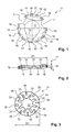
- annular disk-shaped anchoring element 11 has a passage opening 12 for a shaft and at the radial boundary of the passage opening 12 a Ausretesaus principleung 13, which is formed by a radially inwardly open notch.
- the outer periphery 14 of the anchoring element 11 is provided with a profiling in the form of radially outwardly open recesses 15, which form a plurality of easily deflectable fins. Between the largest part of these recesses 15, starting from the outer circumference 14, a plurality of radially inwardly directed slots 16 are provided, which fan out the free edge of the anchoring element 11 in regions and thus allow a simple adaptation thereof to the borehole wall.
- At the outer periphery 14 of the anchoring element 11th are further provided two through holes 17 for a hardenable mass.
- the anchoring element 11 has an outer diameter D1.
- the anchoring element 11 has a wavy configuration in the disk plane ( Fig. 2 ).
- the anchoring element 11 has different thicknesses in the pane plane, wherein in this exemplary embodiment the thickness, starting from the feed-through opening 12, increases in the radial direction to the outside.
- the anchoring element 11 is made of a metal, advantageously made of a steel sheet, in a stamping / bending process.
- annular disk-shaped anchoring element 31 also has a passage opening 32 for a shaft and at the radial boundary of the passage opening 32 a plurality of radially outwardly extending slots as AusretesausEnglishept 33.
- a plurality of radially inwardly extending slots 35 are provided.
- the compensation recess 33 and the slots 35 overlap in regions.
- the anchoring element 31 has an outer diameter D2.
- the anchoring element 31 is made of a plastic, advantageously made of a fiber-reinforced plastic, in an injection molding process.
- FIG. 4 For example, a fastening arrangement 41 for anchoring a fastening element 51 in a borehole 42 by means of a hardenable mass 43 is shown.
- the fastening element 51 has a shaft 52 with an external thread as external profiling 53 and a plurality of mutually spaced anchoring elements 11 and 31, which are each arranged in two groups 54 and 55 on the shaft 52.
- the setting direction-side end 56 of the shaft 52 facing group 55 comprises a plurality of at regular intervals to each other on the shaft 52 arranged anchoring elements 31.
- a further group 54 is provided, the more in Periodically spaced from each other on the shaft 52 arranged anchoring elements 11 comprises.
- anchoring elements 11 and 31 For a group 54 or 55, different embodiments of anchoring elements 11 and 31 can be summarized. Further, it is also possible to vary the distances between the anchoring elements 11 and 31 to each other within a group 54 or 55, which ensures a simple adaptation of the fastening element 51 to local conditions.
- a borehole 42 is first created in the component 44 with a drill, wherein the nominal diameter N of the created borehole 42 is smaller than the outside diameter D1 of the anchoring element 11 and smaller than the outside diameter D2 of the anchoring element 31.
- the borehole depth T is determined on the one hand by the required anchoring length for the fastening element 51 and on the other hand by the required space in front of the fastening element 51 for receiving drilling dust in the borehole 42.
- the wellbore 42 is filled with a defined amount of the hardenable mass 43 and then the fastener 51 is introduced with the setting direction end 56 of the shaft 52 in the first hole 42, wherein the insertion is done manually or by machine.
- the anchoring elements 11 and 31 along the borehole wall, so that it adheres to drilling dust for the most part removed and mixed in the curable mass 43 or is moved to the bottom of the hole.
- the anchoring elements 11 and 31 are pushed, for example, on the shaft 52 or z. B. screwed on this.
- the fastening element 51 is inserted into the borehole 42 and subsequently the hardenable mass 43 is introduced.
- first a small, certain amount of the hardenable mass 43 is introduced into the borehole 42, the fastening element 51 is introduced into the borehole 42 and then a remaining free space of the borehole 42 is filled up with a further amount of the hardenable mass 43.
- the shaft 52 may be provided with an injection bore through which the hardenable mass 43 can be introduced into the borehole 42 after insertion or during the same.
- the fastening element 51 Before hardening of the hardenable mass 43, the fastening element 51 can already be loaded at a limited load level, since the anchoring elements 11 and 31 mechanically anchor the fastening element 51 in the borehole 42. After hardening of the hardenable mass 43, the set fastening element 51 can be loaded to the maximum permissible load level.
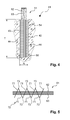
- fastening element 61 has, at its provided with a thread as external profiling 63 shaft 62 an anchoring unit 72 which is formed by a plurality of annular disk-shaped anchoring elements 71, which are each connected at one of its edge portion 73 with each other.
Abstract
Description
Die Erfindung betrifft ein ringscheibenförmiges Verankerungselement zur Anordnung an einem mit einer Aussenprofilierung versehenen Schaft eines Befestigungselementes mit einer Durchführöffnung für den Schaft. Weiter betrifft die Erfindung ein mittels einer aushärtbaren Masse in einem Bohrloch verankerbares Befestigungselement, das zumindest ein ringscheibenförmiges Verankerungselement aufweist, sowie eine Befestigungsanordnung mit einem derartigen Befestigungselement.The invention relates to an annular disk-shaped anchoring element for arrangement on a shaft provided with an external profiling of a fastening element with a passage opening for the shaft. Furthermore, the invention relates to a fastenable by means of a curable material in a wellbore fastener having at least one annular disk-shaped anchoring element, and a fastening arrangement with such a fastener.
Es ist bekannt, Befestigungselemente mit einem eine Aussenprofilierung aufweisenden Schaft mittels einer aushärtbaren Masse, welche vor dem Einführen oder nach dem Einführen des Befestigungselementes in das Bohrloch in dieses eingebracht wird, chemisch im Bohrloch zu verankern. Das Befestigungselement ist beispielsweise eine Gewindestange, die über ihre gesamte Längserstreckung mit einem Gewinde als Aussenprofilierung versehen ist. Wird dieses Befestigungselement chemisch verankert, kann das Versagen des Befestigungspunktes entlang des Kontaktbereichs zwischen dem Schaft und der ausgehärteten Masse oder aber entlang des Kontaktbereichs zwischen der Bohrlochwandung und der ausgehärteten Masse auftreten.It is known to chemically anchor fasteners with a shank having an outer profiling by means of a hardenable mass, which is introduced into the wellbore before insertion or after insertion of the fastener into the wellbore. The fastening element is for example a threaded rod, which is provided over its entire longitudinal extent with a thread as external profiling. When this fastener is chemically anchored, failure of the attachment point may occur along the contact area between the shaft and the cured mass or along the contact area between the borehole wall and the cured mass.
Durch Reinigung des Bohrlochs und insbesondere der Bohrlochwandung kann die Haftung der ausgehärteten Masse an der Bohrlochwandung und somit die Verankerung des Befestigungselementes im Bohrloch verbessert werden. Die Reinigung des Bohrlochs stellt einen zusätzlichen Arbeitsaufwand dar, welcher zudem für ein vorteilhaftes Ergebnis separate Hilfsmittel erfordert, die dem Anwender nicht immer zur Verfügung stehen.By cleaning the borehole and in particular the borehole wall, the adhesion of the hardened mass to the borehole wall and thus the anchoring of the fastening element in the borehole can be improved. The cleaning of the borehole represents an additional workload, which also requires for a beneficial result separate tools that are not always available to the user.
Aus der
Nachteilig an der bekannten Lösung ist, dass aufgrund der Aussenprofilierung des Schafts die ringscheibenförmigen Verankerungselemente im angeordneten Zustand leicht zu einer in Bezug auf die Schaftlängsachse senkrechte Ebene geneigt sind, weshalb der aus dem Bohrloch ragende Schaftabschnitt nach dem Setzen des Befestigungselements nicht senkrecht von der Oberfläche des Bauteils abragt. Eine nachträgliche Justierung des Schafts ist, wenn überhaupt, nur bedingt möglich, da diese entgegen einer von dem zumindest einen Verankerungselement erzeugten Gegenkraft erfolgt.A disadvantage of the known solution is that due to the external profiling of the shaft, the annular disk-shaped anchoring elements in the arranged state are inclined slightly to a plane perpendicular to the shaft longitudinal axis, which is why the protruding from the well shaft portion after setting the fastener is not perpendicular to the surface of the Protrudes component. A subsequent adjustment of the shaft is, if at all, only possible to a limited extent, since this takes place counter to an opposing force generated by the at least one anchoring element.
Aufgabe der Erfindung ist es, einerseits ein Verankerungselement zu schaffen, das einfach an einem Schaft mit einer Aussenprofilierung montierbar ist und den Setzaufwand eines Befestigungselementes reduziert. Ferner soll ein chemisch verankerbares Befestigungselement mit zumindest einem Verankerungselement sowie eine Befestigungsanordnung mit einem derartigen Befestigungselement geschaffen werden, bei denen der Setzaufwand reduziert ist.The object of the invention is, on the one hand to provide an anchoring element which is easy to mount on a shaft with an external profile and reduces the setting of a fastener. Furthermore, a chemically anchored fastener with at least one anchoring element and a fastening arrangement with such a fastener to be created in which the setting effort is reduced.
Diese Aufgabe ist für ein Verankerungselement, für ein Befestigungselement und für eine Befestigungsanordnung durch die Merkmale der unabhängigen Ansprüche gelöst. Vorteilhafte Weiterbildungen sind in den Unteransprüchen dargelegt.This object is achieved for an anchoring element, for a fastening element and for a fastening arrangement by the features of the independent claims. Advantageous developments are set forth in the subclaims.
Gemäss der Erfindung ist zumindest eine zur Durchführöffnung hin offene und zu dieser radial aussenliegende Ausgleichsausnehmung vorgesehen.According to the invention, at least one compensating recess is provided which is open towards the through-opening and radially outward therefrom.
Mit der zumindest einen Ausgleichsausnehmung lässt sich eine Steigung der Aussenprofilierung am Schaft ausgleichen, so dass das Verankerungselement im angeordneten Zustand im Wesentlichen senkrecht bzw. in einer radial vom Schaft abragenden Ebene ausgerichtet ist. Die von dem Verankerungselement aufgespannte Hauptebene schliesst mit der Schaftlängsachse im montierten Zustand des Verankerungselements an einem Schaft einen Winkel von nahezu 90° ein. Die zumindest eine Ausgleichsausnehmung schliesst sich an die radiale Begrenzung der Durchführöffnung an und erstreckt sich nach radial aussen. Vorteilhaft ist die zumindest eine Ausgleichsausnehmung als Kerbe oder als einseitig begrenzter Schlitz ausgebildet. Eine Justierung eines zumindest ein Verankerungselement aufweisendes Befestigungselementes nach dem Setzen in einem Bohrloch erübrigt sich in den meisten Fällen beziehungsweise ist leicht vorzunehmen.With the at least one compensating recess, a pitch of the outer profiling on the shaft can be compensated, so that the anchoring element in the arranged state is aligned substantially perpendicular or in a plane protruding radially from the shaft. The spanned by the anchoring element main plane encloses with the shaft longitudinal axis in the mounted state of the anchoring element on a shaft at an angle of almost 90 °. The at least one compensating recess adjoins the radial boundary of the passage opening and extends radially outward. Advantageously, the at least one Compensation recess designed as a notch or as a one-sided limited slot. An adjustment of at least one anchoring element exhibiting fastener after setting in a borehole is unnecessary in most cases, or is easy to do.
Die Durchführöffnung weist vorteilhaft eine auf den Schaft des Befestigungselementes abgestimmte Form auf und kann somit auch eine von einem Kreis abweichende Ausgestaltung aufweisen. Vorteilhaft ist die Durchführöffnung konzentrisch zu der den äusseren Umfang des Verankerungselementes bildenden Hülllinie angeordnet. In einer alternativen Ausführung ist die Durchführöffnung versetzt zu einer konzentrischen Anordnung vorgesehen, so dass die Breite des Materialabschnitts zwischen der radialen Begrenzung der Durchführöffnung und der den äusseren Umfang des Verankerungselementes bildenden Hülllinie in Umfangrichtung variiert.The lead-through opening advantageously has a shape which is matched to the shank of the fastening element and can therefore also have a configuration deviating from a circle. Advantageously, the lead-through opening is arranged concentrically to the envelope line forming the outer circumference of the anchoring element. In an alternative embodiment, the passage opening is provided offset to a concentric arrangement, so that the width of the material portion between the radial boundary of the passage opening and the outer periphery of the anchoring element forming enveloping line varies in the circumferential direction.
Vorzugsweise ist der äussere Umfang des Verankerungselementes mit einer Profilierung versehen, welche eine einfache Anpassung des Verankerungselementes an die Ausgestaltung des Bohrlochs gewährleistet. Beispielsweise wird die Profilierung durch nach radial aussen offene Ausnehmungen gebildet. Die Ausnehmungen sind vorteilhaft als einseitig begrenzte Schlitze ausgebildet, die sich ausgehend vom äusseren Umfang in Richtung des Scheibenmittelpunkts erstrecken. Die zwischen den Ausnehmungen liegenden Abschnitte des Verankerungselementes bilden leicht auslenkbare Lamellen aus, womit auch bei einem Verankerungselement aus einem sehr steifen Material die Anpassbarkeit an ein Bohrloch beim Einführen in dasselbe gegeben ist. In einer vorteilhaften, flexiblen Ausführung des Verankerungselementes überlappen sich die zumindest eine Ausgleichsausnehmung und die Ausnehmungen für die Profilierung zumindest bereichsweise. Weiter vorteilhaft sind unterschiedliche Arten von Ausnehmungen am äusseren Umfang des Verankerungselementes vorgesehen. Beispielsweise sind eine erste Art von Schlitzen vorgesehen, welche am äusseren Umfang bewegliche Lamellen ausbilden, und zwischen diesen Schlitzen eine zweite Art von Schlitzen vorgesehen, welche den dazwischen liegenden Rand des Verankerungselementes auffächern.Preferably, the outer periphery of the anchoring element is provided with a profiling, which ensures a simple adaptation of the anchoring element to the configuration of the borehole. For example, the profiling is formed by radially outwardly open recesses. The recesses are advantageously formed as unilaterally limited slots extending from the outer periphery in the direction of the disk center point. The lying between the recesses sections of the anchoring element form easily deflectable lamellae, which is also the case of an anchoring element made of a very rigid material, the adaptability to a borehole during insertion into the same. In an advantageous, flexible embodiment of the anchoring element, the at least one compensating recess and the recesses for the profiling overlap at least in regions. Further advantageous different types of recesses are provided on the outer circumference of the anchoring element. For example, a first type of slits are provided, which form on the outer circumference movable lamellae, and between these slots provided a second type of slits, which fanned the intermediate edge of the anchoring element.
Bevorzugt weist das Verankerungselement in der Scheibenebene eine wellige Ausgestaltung auf, welche trotz der zumindest einen Ausgleichsausnehmung eine ausreichende Steifigkeit des Verankerungselementes insbesondere beim Einführen in ein Bohrloch gewährleistet.Preferably, the anchoring element in the disc plane on a wavy configuration, which ensures despite the at least one compensation recess sufficient rigidity of the anchoring element, especially when inserted into a borehole.
Für eine vorteilhafte Verankerung des Verankerungselementes an der Wandung des Bohrlochs beziehungsweise zur Fixierung am Schaft beträgt die Dicke des Verankerungselementes vorteilhaft 0.01 mm bis 2 mm, besonders vorteilhaft 0.05 mm bis 1 mm.For an advantageous anchoring of the anchoring element on the wall of the borehole or for fixing to the shaft, the thickness of the Anchoring element advantageous 0.01 mm to 2 mm, more preferably 0.05 mm to 1 mm.
Vorzugsweise weist das Verankerungselement in der Scheibenebene unterschiedliche Dicken auf, womit sich das Verformungsverhalten des Verankerungselementes insbesondere beim Einführen in ein Bohrloch vorteilhaft anpassen lässt. In einer besonders vorteilhaften Ausführung nimmt die Dicke ausgehend von der Durchführöffnung in radialer Richtung nach aussen zu, so dass im Kontaktbereich des Verankerungselementes mit der Bohrlochwandung eine vorteilhaft grosse Materialmenge für eine mechanische Verankerung des Befestigungselementes zur Verfügung steht. In einer anderen vorteilhaften Ausführung nimmt die Dicke ausgehend vom äusseren Umfang in radialer Richtung zur Durchführöffnung zu, so dass im Kontaktbereich des Verankerungselementes mit dem Schaft eine vorteilhaft grosse Materialmenge für die Fixierung des Verankerungselementes am Schaft zur Verfügung steht. Weiter kann die Dicke des Verankerungselementes auch einerseits ausgehend von der Durchführöffnung in radialer Richtung nach aussen sowie andererseits ausgehend vom äusseren Umfang in radialer Richtung zur Durchführöffnung zunehmen, so dass der Bereich des Verankerungselementes mit der grössten Materialdicke zwischen dem äusseren Umfang und der Durchführöffnung liegt.Preferably, the anchoring element in the disc plane has different thicknesses, whereby the deformation behavior of the anchoring element can be advantageously adapted in particular when inserted into a borehole. In a particularly advantageous embodiment, the thickness increases starting from the feed-through opening in the radial direction to the outside, so that in the contact region of the anchoring element with the borehole wall an advantageously large amount of material for mechanical anchoring of the fastener is available. In another advantageous embodiment, the thickness increases starting from the outer circumference in the radial direction to the passage opening, so that in the contact region of the anchoring element with the shaft an advantageously large amount of material for the fixation of the anchoring element on the shaft is available. Furthermore, the thickness of the anchoring element can also increase on the one hand, starting from the outlet opening in the radial direction to the outside and on the other hand, starting from the outer circumference in the radial direction to the passage opening, so that the area of the anchoring element with the largest material thickness between the outer periphery and the passage opening.
Bevorzugt ist zumindest eine Durchgangsöffnung für eine aushärtbare Masse im Verankerungselement vorgesehen, damit beim Einführen des Verankerungselements in ein zuvor befülltes Bohrloch der verdrängte Anteil der aushärtbaren Masse einfach das Verankerungselement durchdringen und vollständig umhüllen kann. Wird das Bohrloch erst nach dem Einführen eines Befestigungselementes befüllt, kann durch die zumindest eine Durchgangsöffnung die eingegossene Masse weitgehend unbehindert bis zum Bohrlochgrund fliessen. In einer vorteilhaften Ausführung ist die zumindest eine Durchgangsöffnung am äusseren Umfang des Verankerungselementes vorgesehen. Alternativ oder ergänzend dazu wird im Verankerungselement zumindest eine, umfänglich geschlossene Durchgangsöffnung für die aushärtbare Masse vorgesehen.Preferably, at least one passage opening for a hardenable mass is provided in the anchoring element, so that upon insertion of the anchoring element into a previously filled wellbore, the displaced portion of the hardenable mass can simply penetrate and completely envelop the anchoring element. If the borehole is filled only after the introduction of a fastening element, the cast-in mass can flow largely unhindered as far as the bottom of the borehole through the at least one passage opening. In an advantageous embodiment, the at least one passage opening is provided on the outer circumference of the anchoring element. Alternatively or additionally, at least one circumferentially closed passage opening for the hardenable mass is provided in the anchoring element.
Vorzugsweise ist das Band aus einem Metall, vorteilhaft aus einem Stahlblech gefertigt, womit das Verankerungselement eine ausreichende Steifigkeit aufweist. Eine einfache und wirtschaftliche Herstellung des Verankerungselementes lässt sich insbesondere mit einem Stanz-/Biegeverfahren gewährleisten.Preferably, the band is made of a metal, advantageously made of a steel sheet, whereby the anchoring element has sufficient rigidity. A simple and economical production of the anchoring element can be ensured in particular by means of a stamping / bending process.
In einer alternativen, erfindungsgemässen Ausführungsform ist das Band aus einem Kunststoff, vorteilhaft aus einem faserverstärktem Kunststoff gefertigt. Eine einfache und wirtschaftliche Herstellung des Verankerungselementes lässt sich insbesondere mit einem Spritzgussverfahren gewährleisten.In an alternative, inventive embodiment, the band is made of a plastic, advantageously made of a fiber-reinforced plastic. A simple and Economic production of the anchoring element can be ensured in particular by an injection molding process.
In einer vorteilhaften Ausführung ist das Verankerungselement aus einem nicht leitenden Material gefertigt. In Anwendungen, in denen keine Ströme übertragen werden sollen, z. B. bei Befestigungen von Eisenbahnschwellen, gewährleistet das bandförmige Verankerungselement einen ausreichenden Abstand zwischen dem Schaft und der Bohrlochwandung und ein Fliessen von Strom von dem Bauteil in den Schaft des Befestigungselementes.In an advantageous embodiment, the anchoring element is made of a non-conductive material. In applications where no streams are to be transmitted, e.g. As in fastenings of railway sleepers, the band-shaped anchoring element ensures a sufficient distance between the shaft and the borehole wall and a flow of current from the component into the shaft of the fastening element.
In einer Alternative kann das Band aus einem anderen Material als Metall oder Kunststoff gefertigt sein, sofern dieses Material eine ausreichende mechanische Verankerung eines Befestigungselementes im Bohrloch bis zum Aushärten der aushärtbaren Masse gewährleistet.In an alternative, the band may be made of a material other than metal or plastic, as long as this material ensures sufficient mechanical anchoring of a fastener in the borehole until the hardenable mass hardens.
In einer vorteilhaften Ausführung ist das Verankerungselement aus einem nicht leitenden Material gefertigt. In Anwendungen, in denen keine Ströme übertragen werden sollen, z. B. bei Befestigungen von Eisenbahnschwellen, gewährleistet das Verankerungselement einen ausreichenden Abstand zwischen dem Schaft und der Bohrlochwandung.In an advantageous embodiment, the anchoring element is made of a non-conductive material. In applications where no streams are to be transmitted, e.g. As in fastenings of railway sleepers, the anchoring element ensures a sufficient distance between the shaft and the borehole wall.
Das erfindungsgemässe, mittels einer aushärtbaren Masse in einem Bohrloch verankerbare Befestigungselement, weist einen Schaft mit einer Aussenprofilierung und zumindest ein ringscheibenförmiges Verankerungselement mit einer Durchführöffnung für den Schaft auf, wobei zumindest eine zur Durchführöffnung hin offene und zu dieser radial aussenliegende Ausgleichsausnehmung vorgesehen ist.The fastening element according to the invention, which can be anchored in a borehole by means of a hardenable mass, has a shank with an external profiling and at least one annular disk-shaped anchoring element with a passage opening for the shank, wherein at least one compensation recess is provided which is open towards the opening and radially outward therefrom.
Dieses Befestigungselement lässt sich einfach herstellen und ermöglicht eine einfache Montage in einem Bohrloch eines Bauteils, wie z. B. in einer Wand oder einer Decke. Die Aussenprofilierung ist beispielsweise ein Gewinde.This fastener is easy to manufacture and allows easy installation in a borehole of a component, such. B. in a wall or a ceiling. The outer profiling is for example a thread.
Das zumindest eine ringscheibenförmige Verankerungselement des Befestigungselements kann einzelne sowie auch sämtliche Merkmale des zuvor beschriebenen Verankerungselementes aufweisen.The at least one annular disk-shaped anchoring element of the fastening element can have individual as well as all features of the anchoring element described above.
Bevorzugt sind mehrere Verankerungselemente beabstandet zueinander an dem Schaft vorgesehen, womit eine vorteilhafte mechanische Verankerung des Befestigungselementes, eine einfache Ausrichtung des Befestigungselementes im Bohrloch sowie eine vorteilhafte Bewehrung der ausgehärteten Masse gewährleistet ist. Vorteilhaft sind die Verankerungselemente in regelmässigen Abständen zueinander am Schaft angeordnet. Vorzugsweise sind verschiedene Ausgestaltungen von Verankerungselementen an einem Schaft vorgesehen, womit sich in verschiedenen Verankerungstiefen unterschiedliche Verankerungseigenschaften bedarfsweise miteinander kombinieren lassen. Beispielsweise werden ringscheibenförmige Verankerungselemente mit hülsenförmigen oder schraubenförmigen Verankerungselementen an einem Schaft kombiniert.Preferably, a plurality of anchoring elements are provided spaced from each other on the shaft, whereby an advantageous mechanical anchoring of the fastening element, a simple orientation of the fastening element in the borehole and an advantageous reinforcement of the hardened mass is ensured. Advantageously, the anchoring elements are arranged at regular intervals from each other on the shaft. Preferably, various embodiments of anchoring elements are provided on a shaft, which can be combined with each other in different anchoring depths different anchoring properties, if necessary. For example, annular disc-shaped anchoring elements are combined with sleeve-shaped or helical anchoring elements on a shaft.
Bevorzugt sind zumindest zwei ringscheibenförmige Verankerungselemente jeweils an einem ihrer Randabschnitte miteinander zu einer Verankerungseinheit verbunden, wobei der Schaft durch alle miteinander verbundenen ringscheibenförmigen Verankerungselemente hindurchgeführt ist. Für eine Verbindung der zumindest zwei ringscheibenförmigen Verankerungselemente sind diese beispielsweise in einem Stanz-/Biegeverfahren nicht vollständig voneinander getrennt worden oder über einen Befestigungspunkt, z. B. Löt- oder Klebepunkt, beziehungsweise über ein Klemm- oder Haltemittel miteinander verbunden. Vorteilhaft sind mehr als zwei ringscheibenförmige Verankerungselemente jeweils alternierend an gegenüberliegenden Randabschnitten miteinander verbunden. Besonders vorteilhaft lässt sich der Abstand der Verankerungselemente durch Zusammendrücken beziehungsweise durch Auseinaderziehen der Verankerungseinheit an das Befestigungselement oder an die Verankerungslänge in einem Bohrloch einfach anpassen.Preferably, at least two annular disk-shaped anchoring elements are each connected to one another at one of their edge sections to form an anchoring unit, wherein the shaft is guided through all interconnected annular disk-shaped anchoring elements. For a connection of the at least two annular disk-shaped anchoring elements, for example, these have not been completely separated from one another in a punching / bending process or via an attachment point, for. As soldering or gluing point, or connected to each other via a clamping or holding means. Advantageously, more than two annular disk-shaped anchoring elements are connected to each other alternately at opposite edge portions. Particularly advantageously, the distance between the anchoring elements by compressing or by Auseinaderziehen the anchoring unit to the fastener or to the anchoring length in a borehole easily adjust.
Die erfindungsgemässe Befestigungsanordnung eines Befestigungselementes in einem Bohrloch, das einen Nenndurchmesser aufweist, mittels einer aushärtbaren Masse, umfasst ein Befestigungselement mit einem Schaft, der eine Aussenprofilierung aufweist, sowie mit zumindest einem ringscheibenförmigen Verankerungselement, das eine Durchführöffnung für den Schaft und einen Aussendurchmesser aufweist, der grösser als der Nenndurchmesser des Bohrlochs ist, wobei zumindest eine zur Durchführöffnung hin offene und zu dieser radial aussenliegende Ausgleichsausnehmung vorgesehen ist.The fastening arrangement according to the invention of a fastening element in a borehole having a nominal diameter by means of a hardenable mass comprises a fastening element with a shank which has an outer profiling and with at least one annular disk-shaped anchoring element which has a passage opening for the shank and an outer diameter which greater than the nominal diameter of the borehole, wherein at least one to the passage opening is open and provided to this radially outward Ausgleichsausnehmung.
Beim Einführen des Befestigungselementes in das Bohrloch erfolgt durch das Streifen des Verankerungselementes entlang der Bohrlochwandung gleichzeitig eine Reinigung des Bohrlochs, wobei das anfallende Bohrmehl am Bohrlochgrund und gegebenenfalls in der aushärtbaren Masse gesammelt wird und nicht mehr zu einem grossen Teil in die Umgebungsluft entweicht. Eine separate Reinigung des Bohrlochs vor dem Setzen des Befestigungselementes ist nicht mehr erforderlich, wobei trotzdem hohe Endlasten mit dem verankerten Befestigungselement erreicht werden. Des Weiteren gewährleistet das zumindest eine Verankerungselement einen Spritzschutz beim Einführen des Befestigungselementes in das Bohrloch gegen herausspritzende aushärtbare Masse.When inserting the fastener into the wellbore is carried out by the strip of anchoring element along the borehole wall simultaneously cleaning the borehole, the resulting drill dust is collected at the bottom of the hole and possibly in the hardenable mass and no longer escapes to a large extent in the ambient air. A separate cleaning of the borehole before setting the fastener is no longer required, yet high final loads are achieved with the anchored fastener. Furthermore, the at least one anchoring element ensures a splash guard during insertion of the fastening element into the borehole against ejecting hardenable mass.
Durch den Wegfall des Reinigungsschritts wird die Anwendungssicherheit erhöht und das Setzen des Befestigungselementes beschleunigt. Es werden keine zusätzlichen Geräte benötigt und die Umgebungsluft wird nicht durch Bohrmehl zusätzlich belastet. Des Weiteren gewährleisten Befestigungselemente, insbesondere mit mehreren Verankerungselementen, eine ausreichende Überdeckung des Schafts entlang dessen gesamten Verankerungslänge mit der aushärtbaren Masse im Bohrloch.By eliminating the cleaning step, the application security is increased and accelerates the setting of the fastener. No additional equipment is required and the ambient air is not additionally burdened by drilling dust. Furthermore, fastening elements, in particular with a plurality of anchoring elements, ensure adequate covering of the shaft along its entire anchoring length with the hardenable mass in the borehole.
Das zumindest eine ringscheibenförmige Verankerungselement beziehungsweise das Befestigungselement kann einzelne sowie auch sämtliche Merkmale des zuvor beschriebenen Verankerungselementes beziehungsweise des zuvor beschriebenen Befestigungselementes aufweisen.The at least one annular disk-shaped anchoring element or the fastening element can have individual as well as all features of the anchoring element or the fastening element described above.
Die Erfindung wird nachstehend anhand von Ausführungsbeispielen näher erläutert. Es zeigen:
- Fig. 1
- Ein erstes Ausführungsbeispiel eines Verankerungselementes im Grundriss;
- Fig. 2
- das in
Fig. 1 gezeigte Verankerungselement in Seitenansicht; - Fig. 3
- ein zweites Ausführungsbeispiel eines Verankerungselementes im Grundriss;
- Fig. 4
- eine Befestigungsanordnung mit einem Befestigungselement im Schnitt; und
- Fig. 5
- eine Variante eines schematisch dargestellten Befestigungselementes in Seitenansicht.
- Fig. 1
- A first embodiment of an anchoring element in plan view;
- Fig. 2
- this in
Fig. 1 shown anchoring element in side view; - Fig. 3
- a second embodiment of an anchoring element in plan view;
- Fig. 4
- a fastening arrangement with a fastening element in section; and
- Fig. 5
- a variant of a schematically illustrated fastener in side view.
Grundsätzlich sind in den Figuren gleiche Teile mit den gleichen Bezugszeichen versehen.Basically, the same parts are provided with the same reference numerals in the figures.
Das in den
Das Verankerungselement 11 weist in der Scheibenebene eine wellige Ausgestaltung auf (
Das Verankerungselement 11 ist aus einem Metall, vorteilhaft aus einem Stahlblech, in einem Stanz-/Biegeverfahren gefertigt.The anchoring
Da das Verankerungselement 11 im gesetzten Zustand vollständig von der aushärtbaren Masse 43 umgeben sind, ist auch bei einer geringen Materialdicke E ein Ausknicken desselben unter Last bereits vor dem vollständigen Aushärten der aushärtbaren Masse 43 verhindert.Since the anchoring
Das in der
Das Verankerungselement 31 ist aus einem Kunststoff, vorteilhaft aus einem faserverstärkten Kunststoff, in einem Spritzgussverfahren gefertigt.The anchoring
In der
Das Befestigungselement 51 weist einen Schaft 52 mit einem Aussengewinde als Aussenprofilierung 53 sowie mehrere zueinander beabstandete Verankerungselemente 11 und 31 auf, die jeweils in zwei Gruppen 54 und 55 am Schaft 52 angeordnet sind. Die dem setzrichtungsseitigen Ende 56 des Schafts 52 zugewandte Gruppe 55 umfasst mehrere in regelmässigen Abständen zueinander am Schaft 52 angeordnete Verankerungselemente 31. In einem Abstand zu der Gruppe 55 ist eine weitere Gruppe 54 vorgesehen, die mehrere in regelmässigen Abständen zueinander am Schaft 52 angeordnete Verankerungselemente 11 umfasst.The
Zu einer Gruppe 54 oder 55 können auch unterschiedliche Ausgestaltungen von Verankerungselementen 11 und 31 zusammengefasst werden. Weiter ist es zudem möglich, die Abstände der Verankerungselemente 11 und 31 zueinander innerhalb einer Gruppe 54 oder 55 zu variieren, was eine einfache Anpassung des Befestigungselementes 51 an örtliche Gegebenheiten sicherstellt.For a
Zum Setzen des Befestigungselementes 51 wird in dem Bauteil 44 zuerst ein Bohrloch 42 mit einem Bohrer erstellt, wobei der Nenndurchmesser N des erstellten Bohrlochs 42 kleiner als der Aussendurchmesser D1 des Verankerungselementes 11 sowie kleiner als der Aussendurchmesser D2 des Verankerungselementes 31 gewählt ist. Die Bohrlochtiefe T wird einerseits durch die erforderliche Verankerungslänge für das Befestigungselement 51 und andererseits durch den erforderlichen Raum vor dem Befestigungselement 51 zur Aufnahme von Bohrmehl im Bohrloch 42 bestimmt.To set the
Anschliessend wird das Bohrloch 42 mit einer definierten Menge der aushärtbaren Masse 43 befüllt und dann das Befestigungselement 51 mit dem setzrichtungsseitigen Ende 56 des Schafts 52 voran in das Bohrloch 42 eingeführt, wobei das Einführen manuell oder auch maschinell erfolgt. Dabei streifen die Verankerungselemente 11 und 31 entlang der Bohrlochwandung, so dass daran anhaftendes Bohrmehl zum grössten Teil von diesen entfernt und in die aushärtbare Masse 43 eingemischt beziehungsweise zum Bohrlochgrund hin bewegt wird. Die Verankerungselemente 11 und 31 sind beispielsweise auf den Schaft 52 aufgeschoben oder werden z. B. auf diesen aufgeschraubt. Beim Einführen des Befestigungselementes 51 durchströmt und umspült die aushärtbare Masse 43 die Verankerungselemente 11 und 31 durch die Durchgangsöffnungen 17 und Ausnehmungen 15 beziehungsweise durch die Schlitze 33 und 35, so dass die aushärtbare Masse 43 und allenfalls darin befindliches Bohrmehl gleichmässig durchmischt wird und die Verankerungselemente 11 und 31 nach dem Aushärten der Masse 43 weitgehend vollständig in dieser eingebettet sind.Subsequently, the
Alternativ wird zuerst das Befestigungselement 51 in das Bohrloch 42 eingeführt und anschliessend die aushärtbare Masse 43 eingebracht. In einer weiteren Alternative wird zuerst eine kleine, bestimmte Menge der aushärtbare Masse 43 in das Bohrloch 42 eingebracht, das Befestigungselement 51 in das Bohrloch 42 eingeführt und anschliessend ein noch verbleibender Freiraum des Bohrlochs 42 mit einer weiteren Menge der aushärtbaren Masse 43 aufgefüllt.Alternatively, first the
Weiter kann der Schaft 52 mit einer Injektionsbohrung versehen sein, durch welche die aushärtbare Masse 43 nach dem Einführen oder während demselben in das Bohrloch 42 einbringbar ist.Furthermore, the
Vor dem Aushärten der aushärtbaren Masse 43 ist das Befestigungselement 51 bereits auf einem beschränkten Lastniveau belastbar, da die Verankerungselemente 11 und 31 das Befestigungselement 51 mechanisch im Bohrloch 42 verankern. Nach dem Aushärten der aushärtbaren Masse 43 ist das gesetzte Befestigungselement 51 auf das maximal zulässige Lastniveau belastbar.Before hardening of the
Da der äussere Umfang 14 bzw. 34 der Verankerungselemente 11 bzw. 31 weiterhin zumindest bereichsweise in die Bohrlochwandung eingreift, steht eine ausreichende Kontaktfläche zur Verfügung, womit die Befestigungsanordnung 41 auch in gerissenem Beton anwendbar ist.Since the
Das in der
Claims (12)
zumindest eine zur Durchführöffnung (12; 32) hin offenen und zu dieser radial aussenliegenden Ausgleichsausnehmung (13; 33).Annular disk-shaped anchoring element (11; 31; 71) for arranging on a shaft (52; 62) of a fastening element (51; 61) provided with an external profiling (53) with a passage opening (12; 32) for the shaft (52; 62), marked by
at least one compensating recess (13, 33) open towards the opening (12, 32) and radially outward therefrom.
Applications Claiming Priority (1)
| Application Number | Priority Date | Filing Date | Title |
|---|---|---|---|
| DE102008040677A DE102008040677A1 (en) | 2008-07-24 | 2008-07-24 | Annular disk-shaped anchoring element |
Publications (2)
| Publication Number | Publication Date |
|---|---|
| EP2148098A2 true EP2148098A2 (en) | 2010-01-27 |
| EP2148098A3 EP2148098A3 (en) | 2011-05-11 |
Family
ID=41119324
Family Applications (1)
| Application Number | Title | Priority Date | Filing Date |
|---|---|---|---|
| EP09163777A Withdrawn EP2148098A3 (en) | 2008-07-24 | 2009-06-25 | Disc-form anchoring element |
Country Status (5)
| Country | Link |
|---|---|
| US (1) | US20100021261A1 (en) |
| EP (1) | EP2148098A3 (en) |
| JP (1) | JP5464933B2 (en) |
| CA (1) | CA2671583A1 (en) |
| DE (1) | DE102008040677A1 (en) |
Cited By (2)
| Publication number | Priority date | Publication date | Assignee | Title |
|---|---|---|---|---|
| CN107183092A (en) * | 2017-06-22 | 2017-09-22 | 无锡市锡东金属磁材厂 | Converter spindle spacer |
| CN107197889A (en) * | 2017-06-22 | 2017-09-26 | 无锡市锡东金属磁材厂 | Hot-air rotary furnace spindle spacer |
Families Citing this family (5)
| Publication number | Priority date | Publication date | Assignee | Title |
|---|---|---|---|---|
| US9362634B2 (en) * | 2011-12-27 | 2016-06-07 | Perfectvision Manufacturing, Inc. | Enhanced continuity connector |
| CN103085977A (en) * | 2013-02-04 | 2013-05-08 | 哈尔滨东安发动机(集团)有限公司 | Aluminum foil adjustable pad used for helicopter transmission system |
| JP6513501B2 (en) * | 2015-06-15 | 2019-05-15 | 大豊工業株式会社 | Washer manufacturing method and washer |
| US10472999B2 (en) * | 2016-08-18 | 2019-11-12 | Ford Global Technologies, Llc | Methods and system for adjusting camshafts |
| JP2018080495A (en) * | 2016-11-16 | 2018-05-24 | 株式会社ティ・エス・プランニング | Anchor fixture |
Citations (1)
| Publication number | Priority date | Publication date | Assignee | Title |
|---|---|---|---|---|
| US1688087A (en) | 1927-07-12 | 1928-10-16 | Richard A Mirzan | Means for anchoring bolts |
Family Cites Families (22)
| Publication number | Priority date | Publication date | Assignee | Title |
|---|---|---|---|---|
| US2012032A (en) * | 1932-08-11 | 1935-08-20 | William E Zinnbauer | Lock washer |
| US2158378A (en) * | 1937-03-20 | 1939-05-16 | Illinois Tool Works | Lock washer |
| GB664218A (en) * | 1948-09-17 | 1952-01-02 | United Carr Fastener Corp | Improvements in and relating to screw fasteners |
| US2640219A (en) * | 1949-06-28 | 1953-06-02 | United Carr Fastener Corp | Furniture glider |
| US3149655A (en) * | 1961-08-14 | 1964-09-22 | Illinois Tool Works | Twisted tooth lock washer |
| FR88658E (en) * | 1965-01-25 | 1967-03-10 | Method and device for sealing support, in particular for roofs and mine faces | |
| GB2124726A (en) * | 1982-07-29 | 1984-02-22 | Illinois Tool Works | Anchors for securing by expansion |
| EP0181945B1 (en) * | 1984-10-24 | 1988-09-21 | Georg Walz | Method of sealing a tube or a rod in an opening of a construction element |
| US4812193A (en) * | 1986-12-22 | 1989-03-14 | Gauron Richard F | Inset panel fastener and method of using |
| DE3873486T2 (en) * | 1987-11-12 | 1992-12-03 | David Patrick Payne | METHOD AND MEANS FOR CONNECTING COMPONENTS. |
| JP2759126B2 (en) * | 1988-06-29 | 1998-05-28 | 清水建設株式会社 | Embedded structure of anchor |
| US4958970A (en) * | 1988-08-17 | 1990-09-25 | The United States Of America As Represented By The Secretary Of The Navy | Graduated-load spring washer system for screws and threaded fasteners |
| DE4010051C1 (en) * | 1990-03-29 | 1991-08-08 | Upat Gmbh & Co, 7830 Emmendingen, De | |
| GB9115850D0 (en) * | 1991-07-23 | 1991-09-04 | Univ Manchester | Coupling |
| US5188494A (en) * | 1992-04-21 | 1993-02-23 | Itt Corporation | Torque indicator device and method for use with a threaded fastener |
| US5205693A (en) * | 1992-05-11 | 1993-04-27 | Fuller S Wyatt | Quick release bolt |
| US5857817A (en) * | 1995-04-28 | 1999-01-12 | Anthony C. Giannuzzi | Centering sleeve and overflow member assembly for masonry installations |
| US5562377A (en) * | 1995-04-28 | 1996-10-08 | Giannuzzi; Louis N. | Anchor sleeve and bolt assembly |
| JP3238327B2 (en) * | 1996-06-27 | 2001-12-10 | 株式会社オー・ピー・ジ | Nuts with washers for wood fastening |
| US6393795B1 (en) * | 2000-08-16 | 2002-05-28 | Illinois Tool Works Inc. | Adhesive anchor and system |
| US6468011B2 (en) * | 2001-01-31 | 2002-10-22 | Hewlett-Packard Company | Precision fastener assembly having a pre-compressed captive spring |
| US6705813B2 (en) * | 2002-02-07 | 2004-03-16 | Pierre P. Schwab | Snap disc device |
-
2008
- 2008-07-24 DE DE102008040677A patent/DE102008040677A1/en not_active Withdrawn
-
2009
- 2009-06-25 EP EP09163777A patent/EP2148098A3/en not_active Withdrawn
- 2009-07-08 CA CA2671583A patent/CA2671583A1/en not_active Abandoned
- 2009-07-16 US US12/460,463 patent/US20100021261A1/en not_active Abandoned
- 2009-07-22 JP JP2009171434A patent/JP5464933B2/en not_active Expired - Fee Related
Patent Citations (1)
| Publication number | Priority date | Publication date | Assignee | Title |
|---|---|---|---|---|
| US1688087A (en) | 1927-07-12 | 1928-10-16 | Richard A Mirzan | Means for anchoring bolts |
Cited By (2)
| Publication number | Priority date | Publication date | Assignee | Title |
|---|---|---|---|---|
| CN107183092A (en) * | 2017-06-22 | 2017-09-22 | 无锡市锡东金属磁材厂 | Converter spindle spacer |
| CN107197889A (en) * | 2017-06-22 | 2017-09-26 | 无锡市锡东金属磁材厂 | Hot-air rotary furnace spindle spacer |
Also Published As
| Publication number | Publication date |
|---|---|
| CA2671583A1 (en) | 2010-01-24 |
| JP5464933B2 (en) | 2014-04-09 |
| US20100021261A1 (en) | 2010-01-28 |
| JP2010032047A (en) | 2010-02-12 |
| DE102008040677A1 (en) | 2010-01-28 |
| EP2148098A3 (en) | 2011-05-11 |
Similar Documents
| Publication | Publication Date | Title |
|---|---|---|
| EP2148098A2 (en) | Disc-form anchoring element | |
| EP1591596A2 (en) | Embedded dowel | |
| EP2691659B1 (en) | Fastening anchor and fastening device | |
| EP2148100B1 (en) | Anchoring element | |
| EP2148099B1 (en) | Anchoring element | |
| EP2128458B1 (en) | Fastening element | |
| DE102009028545A1 (en) | anchoring sleeve | |
| DE102008001552A1 (en) | mounting assembly | |
| EP0622553B1 (en) | Nail with zone for spreading | |
| EP2039845A2 (en) | Mounting element for attaching insulation boards to a substructure | |
| DE19744728A1 (en) | Drive-in dowels | |
| DE4331583A1 (en) | Nail with a spreading area | |
| EP2009296B1 (en) | Chemically fixable fastening element | |
| EP0670429A1 (en) | Fastening element anchored by driving | |
| DE2605732A1 (en) | DOWEL-LIKE FASTENING ELEMENT | |
| DE4423234A1 (en) | Fastener | |
| EP0701068A1 (en) | Insulation anchor dowell | |
| DE19610442A1 (en) | Drilling tool | |
| EP3165779B1 (en) | Clamping anchor to be anchored in a drill hole, and assembly comprising such a clamping anchor | |
| DE3934554A1 (en) | Knock in anchor for bore holes - has conical knock in pin with sharp edges steps round incision | |
| EP3135927A1 (en) | Screw for screwing into a screw-hole and arrangement comprising said screw | |
| DE202020004365U1 (en) | Adjustment dowels and assembly kit | |
| EP2063135B1 (en) | Expansion anchor | |
| DE102007000451A1 (en) | Fastening device for e.g. wire suspension, has sleeve part projecting above fastening part in direction perpendicular to longitudinal axis, and cutting elements provided at front side of sleeve part for cutting subsurface | |
| DE102010026257A1 (en) | Multipart quick assembly bolt for connecting components for manufacturing motor vehicle, has support element exhibiting radially, outwardly directed preload, and fixing pin partially received in passage opening |
Legal Events
| Date | Code | Title | Description |
|---|---|---|---|
| PUAI | Public reference made under article 153(3) epc to a published international application that has entered the european phase |
Free format text: ORIGINAL CODE: 0009012 |
|
| AK | Designated contracting states |
Kind code of ref document: A2 Designated state(s): AT BE BG CH CY CZ DE DK EE ES FI FR GB GR HR HU IE IS IT LI LT LU LV MC MK MT NL NO PL PT RO SE SI SK TR |
|
| AX | Request for extension of the european patent |
Extension state: AL BA RS |
|
| PUAL | Search report despatched |
Free format text: ORIGINAL CODE: 0009013 |
|
| AK | Designated contracting states |
Kind code of ref document: A3 Designated state(s): AT BE BG CH CY CZ DE DK EE ES FI FR GB GR HR HU IE IS IT LI LT LU LV MC MK MT NL NO PL PT RO SE SI SK TR |
|
| AX | Request for extension of the european patent |
Extension state: AL BA RS |
|
| STAA | Information on the status of an ep patent application or granted ep patent |
Free format text: STATUS: THE APPLICATION IS DEEMED TO BE WITHDRAWN |
|
| 18D | Application deemed to be withdrawn |
Effective date: 20111112 |