JP6513501B2 - Washer manufacturing method and washer - Google Patents
Washer manufacturing method and washer Download PDFInfo
- Publication number
- JP6513501B2 JP6513501B2 JP2015120134A JP2015120134A JP6513501B2 JP 6513501 B2 JP6513501 B2 JP 6513501B2 JP 2015120134 A JP2015120134 A JP 2015120134A JP 2015120134 A JP2015120134 A JP 2015120134A JP 6513501 B2 JP6513501 B2 JP 6513501B2
- Authority
- JP
- Japan
- Prior art keywords
- longitudinal member
- washer
- valley
- corrugated
- lower side
- Prior art date
- Legal status (The legal status is an assumption and is not a legal conclusion. Google has not performed a legal analysis and makes no representation as to the accuracy of the status listed.)
- Active
Links
- 238000004519 manufacturing process Methods 0.000 title claims description 21
- 239000000463 material Substances 0.000 claims description 24
- 238000002360 preparation method Methods 0.000 claims description 20
- 239000007769 metal material Substances 0.000 claims description 13
- 230000002093 peripheral effect Effects 0.000 description 19
- 238000000034 method Methods 0.000 description 11
- 230000004048 modification Effects 0.000 description 8
- 238000012986 modification Methods 0.000 description 8
- 239000012778 molding material Substances 0.000 description 6
- 239000010687 lubricating oil Substances 0.000 description 5
- 238000005452 bending Methods 0.000 description 4
- 230000006835 compression Effects 0.000 description 3
- 238000007906 compression Methods 0.000 description 3
- 238000004080 punching Methods 0.000 description 2
- 238000009751 slip forming Methods 0.000 description 2
- 230000007423 decrease Effects 0.000 description 1
- 230000000694 effects Effects 0.000 description 1
- 238000005516 engineering process Methods 0.000 description 1
- 238000000465 moulding Methods 0.000 description 1
- 239000003921 oil Substances 0.000 description 1
- 238000003466 welding Methods 0.000 description 1
Images


Classifications
-
- F—MECHANICAL ENGINEERING; LIGHTING; HEATING; WEAPONS; BLASTING
- F16—ENGINEERING ELEMENTS AND UNITS; GENERAL MEASURES FOR PRODUCING AND MAINTAINING EFFECTIVE FUNCTIONING OF MACHINES OR INSTALLATIONS; THERMAL INSULATION IN GENERAL
- F16B—DEVICES FOR FASTENING OR SECURING CONSTRUCTIONAL ELEMENTS OR MACHINE PARTS TOGETHER, e.g. NAILS, BOLTS, CIRCLIPS, CLAMPS, CLIPS OR WEDGES; JOINTS OR JOINTING
- F16B43/00—Washers or equivalent devices; Other devices for supporting bolt-heads or nuts
-
- B—PERFORMING OPERATIONS; TRANSPORTING
- B21—MECHANICAL METAL-WORKING WITHOUT ESSENTIALLY REMOVING MATERIAL; PUNCHING METAL
- B21D—WORKING OR PROCESSING OF SHEET METAL OR METAL TUBES, RODS OR PROFILES WITHOUT ESSENTIALLY REMOVING MATERIAL; PUNCHING METAL
- B21D11/00—Bending not restricted to forms of material mentioned in only one of groups B21D5/00, B21D7/00, B21D9/00; Bending not provided for in groups B21D5/00 - B21D9/00; Twisting
- B21D11/10—Bending specially adapted to produce specific articles, e.g. leaf springs
-
- B—PERFORMING OPERATIONS; TRANSPORTING
- B21—MECHANICAL METAL-WORKING WITHOUT ESSENTIALLY REMOVING MATERIAL; PUNCHING METAL
- B21D—WORKING OR PROCESSING OF SHEET METAL OR METAL TUBES, RODS OR PROFILES WITHOUT ESSENTIALLY REMOVING MATERIAL; PUNCHING METAL
- B21D11/00—Bending not restricted to forms of material mentioned in only one of groups B21D5/00, B21D7/00, B21D9/00; Bending not provided for in groups B21D5/00 - B21D9/00; Twisting
- B21D11/20—Bending sheet metal, not otherwise provided for
-
- B—PERFORMING OPERATIONS; TRANSPORTING
- B21—MECHANICAL METAL-WORKING WITHOUT ESSENTIALLY REMOVING MATERIAL; PUNCHING METAL
- B21D—WORKING OR PROCESSING OF SHEET METAL OR METAL TUBES, RODS OR PROFILES WITHOUT ESSENTIALLY REMOVING MATERIAL; PUNCHING METAL
- B21D53/00—Making other particular articles
- B21D53/16—Making other particular articles rings, e.g. barrel hoops
- B21D53/20—Making other particular articles rings, e.g. barrel hoops washers, e.g. for sealing
-
- B—PERFORMING OPERATIONS; TRANSPORTING
- B21—MECHANICAL METAL-WORKING WITHOUT ESSENTIALLY REMOVING MATERIAL; PUNCHING METAL
- B21F—WORKING OR PROCESSING OF METAL WIRE
- B21F37/00—Manufacture of rings from wire
- B21F37/04—Manufacture of rings from wire of washers
-
- B—PERFORMING OPERATIONS; TRANSPORTING
- B21—MECHANICAL METAL-WORKING WITHOUT ESSENTIALLY REMOVING MATERIAL; PUNCHING METAL
- B21D—WORKING OR PROCESSING OF SHEET METAL OR METAL TUBES, RODS OR PROFILES WITHOUT ESSENTIALLY REMOVING MATERIAL; PUNCHING METAL
- B21D13/00—Corrugating sheet metal, rods or profiles; Bending sheet metal, rods or profiles into wave form
-
- B—PERFORMING OPERATIONS; TRANSPORTING
- B21—MECHANICAL METAL-WORKING WITHOUT ESSENTIALLY REMOVING MATERIAL; PUNCHING METAL
- B21D—WORKING OR PROCESSING OF SHEET METAL OR METAL TUBES, RODS OR PROFILES WITHOUT ESSENTIALLY REMOVING MATERIAL; PUNCHING METAL
- B21D28/00—Shaping by press-cutting; Perforating
- B21D28/02—Punching blanks or articles with or without obtaining scrap; Notching
- B21D28/06—Making more than one part out of the same blank; Scrapless working
Description
本発明は、荷重を受けるためのワッシャの製造方法及びワッシャの技術に関する。 The present invention relates to a method of manufacturing a washer for receiving a load and the technology of the washer.
従来、荷重を受けるためのワッシャは、略板状に形成される成形材料を成形用金型によって打ち抜くことで成形される。例えば、特許文献1に記載の如くである。
Conventionally, a washer for receiving a load is molded by punching out a molding material formed in a substantially plate shape with a molding die. For example, it is as described in
しかしながら、特許文献1に記載の技術では、成形材料をリング状に打ち抜くため、成形材料の多くが無駄になってしまう。また、例えば、成形材料を半円状に打ち抜いて、二個の半円状の部材同士を接合する場合でも、依然として多くの成形材料が無駄になってしまい、材料歩留まりを十分に向上することができるとは言い難い(図9に示すスクラップS901参照)。以上のように、従来技術においては、材料歩留まりが悪いという点で不利であった。
However, in the technique described in
本発明は、以上の如き状況を鑑みてなされたものであり、その解決しようとする課題は材料歩留まりを向上することができるワッシャの製造方法及びワッシャを提供するものである。 The present invention has been made in view of the above circumstances, and an object of the present invention is to provide a washer manufacturing method and a washer capable of improving material yield.
本発明の解決しようとする課題は以上の如くであり、次にこの課題を解決するための手段を説明する。 The problem to be solved by the present invention is as described above, and next, means for solving the problem will be described.
即ち、請求項1においては、短手方向の一側面及び他側面のそれぞれに形成される山部、及び当該山部に対して長手方向に連続する谷部を有する波型部を具備し、前記一側面に形成される山部と前記他側面に形成される谷部の形状が同一であり、かつ前記一側面に形成される谷部と前記他側面に形成される山部の形状が同一である長手部材を準備する準備工程と、前記一側面及び前記他側面が前記短手方向及び前記長手方向と直交する一方向から見て円弧状となるように、前記長手部材を変形させる変形工程と、を具備するものである。 That is, in the first aspect, the mountain portion formed on each of one side and the other side in the lateral direction, and comprises a corrugated section having a trough portion continuing in the longitudinal direction with respect to the crests, the The shape of the valley formed on one side is the same as the shape of the valley formed on the other side, and the shape of the valley formed on the one side and the ridge formed on the other side is the same A preparing step of preparing a certain longitudinal member, and a deforming step of deforming the longitudinal member so that the one side surface and the other side surface have an arc shape when viewed from one direction orthogonal to the short side direction and the longitudinal direction , And.
請求項2においては、前記準備工程で準備される前記長手部材の前記一側面又は前記他側面の少なくともいずれか一方は、前記長手方向における一端部から他端部に亘って前記波型部が形成されるものである。 In the second aspect, at least one of the one side surface or the other side surface of the longitudinal member prepared in the preparation step has the corrugated portion formed from one end to the other end in the longitudinal direction. It is
請求項3においては、前記準備工程で準備される前記長手部材の前記谷部は、先端部が前記一方向から見て弧状に形成されるものである。 According to the third aspect of the present invention, the valleys of the longitudinal member prepared in the preparing step are formed in an arc shape as viewed from the one direction.
請求項4においては、前記準備工程で準備される前記長手部材の前記波型部は、前記一方向から見て正弦波状に形成されるものである。 According to a fourth aspect of the present invention, the corrugated portion of the longitudinal member prepared in the preparing step is formed in a sine wave as viewed from the one direction.
請求項5においては、前記変形工程は、前記波型部が少なくとも外周側に配置されるように、前記長手部材を変形させるものである。 In the fifth aspect, in the deformation step, the longitudinal member is deformed such that the corrugated portion is disposed at least on the outer peripheral side.
請求項6においては、前記準備工程で準備される前記長手部材の前記一側面及び前記他側面は、前記一側面から前記他側面までの前記短手方向に沿った距離が、前記長手方向の一端部から他端部に亘って一定に形成されるものである。 In the sixth aspect, the one side surface and the other side surface of the longitudinal member prepared in the preparation step have one end in the longitudinal direction at a distance from the one side surface to the other side surface along the short side direction. It is formed uniformly from the part to the other end.
請求項7においては、前記準備工程で準備される前記長手部材は、異なる複数の金属材料からなるバイメタル材によって構成されるものである。
In
請求項8においては、外周面及び内周面のそれぞれに形成される山部、及び当該山部に対して周方向に連続する谷部を有する波型部を具備し、前記山部及び前記谷部は、厚み方向から見て弧状に形成されるものである。 According to an eighth aspect of the present invention, there is provided a peak portion formed on each of the outer peripheral surface and the inner peripheral surface, and a corrugated portion having a valley portion continuous in the circumferential direction with respect to the peak portion; The portion is formed in an arc shape as viewed from the thickness direction .
本発明の効果として、以下に示すような効果を奏する。 The effects of the present invention are as follows.
請求項1においては、材料歩留まりを向上することができると共に長手部材を簡単に曲げることができる。 According to the first aspect, the material yield can be improved and the longitudinal member can be bent easily .
請求項2においては、応力を分散させることができる。
In
請求項3においては、谷部の広い範囲に応力を分散させることができる。 In claim 3, stress can be dispersed in a wide range of valleys.
請求項4においては、長手部材を滑らかに変形させることができる。 In the fourth aspect, the longitudinal member can be deformed smoothly.
請求項5においては、潤滑性を向上することができる。 According to the fifth aspect, the lubricity can be improved.
請求項6においては、材料歩留まりを効果的に向上することができる。 In claim 6, the material yield can be effectively improved.
請求項7においては、金属材料が剥離することを抑制できる。
In
請求項8においては、材料歩留まりを向上することができると共に、潤滑性を効果的に向上することができる。 According to the eighth aspect, the material yield can be improved , and the lubricity can be effectively improved .
以下では、図中の矢印U、矢印D、矢印F、矢印B、矢印L及び矢印Rで示した方向を、それぞれ上方向、下方向、前方向、後方向、左方向及び右方向と定義して説明を行う。 In the following, the directions indicated by arrow U, arrow D, arrow F, arrow B, arrow L and arrow R in the figure are respectively defined as upward, downward, forward, backward, leftward and rightward I will explain.
以下では、本発明の一実施形態に係るワッシャ10の製造方法及びワッシャ10について説明する。
Below, the manufacturing method and
図6に示すワッシャ10は、適宜荷重を受けるための部材である。ワッシャ10は、正面視半円状(円弧状)に形成される。本実施形態に係るワッシャ10は、前側面及び後側面に異なる金属材料を貼り合わせたバイメタル材(二種類の金属材料を貼り合わせたバイメタル材)によって構成される。ワッシャ10の製造方法は、このようなワッシャ10を製造するものである。
The
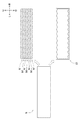
図1に示すように、まず、ワッシャ10の製造方法では、準備工程が行われる(ステップS10)。準備工程は、図2に示す板状部材Nに加工を施して長手部材N1を準備する。図2に示すように、板状部材Nは、板面を前後方向に向けて配置されると共に長手方向を左右方向に向けて配置される部材である。板状部材Nは、前記バイメタル材によって構成される。準備工程において、板状部材Nには、所定の金型によって板面が打ち抜かれる加工であるブランク加工が施される。これによって、板状部材Nは、複数(本実施形態では七個)の長手部材N1と一個のスクラップS1とに分けられる。
As shown in FIG. 1, first, in the method of manufacturing the
図3及び図4に示すように、準備工程で準備された長手部材N1は、長手方向を左右方向に向けて配置される。また、長手部材N1は、短手方向を上下方向に向けて配置される。長手部材N1は、上側波型部20及び下側波型部30を具備する。
As shown in FIG. 3 and FIG. 4, the longitudinal members N1 prepared in the preparation step are arranged with the longitudinal direction oriented in the left-right direction. In addition, the longitudinal member N1 is disposed with its short side directed in the vertical direction. The longitudinal member N <b> 1 includes an upper
上側波型部20は、長手部材N1の上側面に形成される。上側波型部20は、山部21及び谷部22を有する。
The upper
山部21は、長手部材N1の上側面において、上方向(短手方向)に突出するように形成される部分である。山部21の先端部(頂部)21aは、正面視略弧状に形成される。山部21は、長手部材N1の前端部から後端部(前側面から後側面)に亘って形成される。山部21は、後述する谷部22を挟んで左右方向に複数(本実施形態では十一個)形成される。
The
谷部22は、長手部材N1の上側面において、下方向(短手方向)に窪むように形成される部分である。谷部22は、山部21と左右方向に連続するように複数(本実施形態では十二個)形成される。左右中途部に配置される谷部22(左端部及び右端部を除く谷部22)は、山部21の外形と略同一の外形(左右方向幅、上下方向幅及び先端部(底部)22aの形状が略同一)となるように形成される。左端部に配置される谷部22は、左右中途部に配置される谷部22の左半分が切り落とされたような正面視略弧状に形成される。また、右端部に配置される谷部22は、左右中途部に配置される谷部22の右半分が切り落とされたような正面視略弧状に形成される。谷部22は、長手部材N1の前端部から後端部(前側面から後側面)に亘って形成される。
The
このように構成される上側波型部20は、長手部材N1の上側面における左端部から右端部に亘って形成される。これによって、長手部材N1の上側面は、全面に亘って山部21及び谷部22が交互に連続して形成され、正面視略正弦波状に形成される。
The upper side corrugated
下側波型部30は、長手部材N1の下側面に形成される。下側波型部30は、山部31及び谷部32を有する。
The lower side corrugated
山部31は、長手部材N1の下側面において、下方向(短手方向)に突出するように形成される部分である。山部31は、後述する下側波型部30の谷部32を挟んで左右方向に複数(本実施形態では十二個)形成される。左右中途部に配置される山部31(左端部及び右端部を除く山部31)は、上側波型部20の谷部22の外形と略同一の外形(左右方向幅、上下方向幅及び先端部(頂部)31aの形状が略同一)となるように形成される。左端部に配置される山部31は、左右中途部に配置される山部31の左半分が切り落とされたような正面視略弧状に形成される。また、右端部に配置される山部31は、左右中途部に配置される山部31の右半分が切り落とされたような正面視略弧状に形成される。山部31は、長手部材N1の前端部から後端部(前側面から後側面)に亘って形成される。
山部31は、上側波型部20の谷部22の下方にそれぞれ配置される。すなわち、山部31は、上側波型部20の山部21に対して左右方向にずれた位置に配置される。
The
The
谷部32は、長手部材N1の下側面において、上方向(短手方向)に窪むように形成される部分である。谷部32は、上側波型部20の山部21の外形と略同一の外形(左右方向幅、上下方向幅及び先端部(底部)32aの形状が略同一)となるように形成される。谷部32は、山部31と左右方向に連続するように複数(本実施形態では十一個)形成される。谷部32は、長手部材N1の前端部から後端部(前側面から後側面)に亘って形成される。
谷部32は、上側波型部20の山部21の下方にそれぞれ配置される。すなわち、谷部32は、上側波型部20の谷部22に対して左右方向にずれた位置に配置される。
The
The
このように構成される下側波型部30は、長手部材N1の下側面における左端部から右端部に亘って形成される。これによって、長手部材N1の下側面は、全面に亘って下側波型部30の山部31及び谷部32が交互に連続して形成され、正面視略正弦波状に形成される。
The lower side wave-shaped
また、長手部材N1は、上側波型部20の山部21と下側波型部30の谷部32とが左右方向における位置を合わせて配置されると共に、上側波型部20の谷部22と下側波型部30の山部31とが左右方向における位置を合わせて配置される。これにより、長手部材N1は、上下方向幅W(上側面から下側面までの上下方向に沿った距離)が常に一定となるような正面視略正弦波状に形成される。こうして、長手部材N1は、上側面及び下側面が略同一形状に形成される。
また、上側波型部20の谷部22から下側波型部30の谷部32までの上下方向に沿った距離は、上下方向幅Wの半分程度となるように形成される。これにより、本実施形態に係る長手部材N1は、その体積を減らして軽量化することができる。
Further, in the
Further, the distance along the up and down direction from the
図1に示すように、準備工程が行われた後で、ワッシャ10の製造方法では、変形工程が行われる(ステップS20)。変形工程は、長手部材N1を塑性変形させる工程である。変形工程において、長手部材N1は、所定の治具によって拘束される。その後、図5に示すように、右部及び左部が下側(長手部材N1の下方に配置される点C側)に曲げられる。これによって、長手部材N1は、点Cを中心とした正面視半円状に塑性変形される。こうして長手部材N1は、ワッシャ10として形成される。このようなワッシャ10の外周面には、上側波型部20が配置される。また、ワッシャ10の内周面には、下側波型部30が配置される。
As shown in FIG. 1, after the preparation process is performed, the deformation process is performed in the method of manufacturing the washer 10 (step S20). The deformation step is a step of plastically deforming the longitudinal member N1. In the deformation step, the longitudinal member N1 is restrained by a predetermined jig. Thereafter, as shown in FIG. 5, the right and left portions are bent downward (toward point C disposed below the longitudinal member N1). Thus, the longitudinal member N1 is plastically deformed in a semicircular shape in a front view centering on the point C. The longitudinal member N1 is thus formed as a
このような変形工程が行われるとき、上側波型部20の山部21及び谷部22は、ワッシャ10の周方向に伸張される。また、このとき、谷部22(特に、先端部22a)に応力が作用し易い。このため、図5及び図6に示すように、ワッシャ10の外周面(長手部材N1の上側面)においては、谷部22が主に伸張されることとなる。
When such a deformation process is performed, the
なお、図6に破線で示す仮想線L21は、上側波型部20の山部21の先端部21aを結ぶ曲線である。図6に二点鎖線で示す仮想線L22は、上側波型部20の谷部22の先端部22aを結ぶ曲線である。図6に破線で示す仮想線L31は、下側波型部30の山部31の先端部31aを結ぶ曲線である。図6に二点鎖線で示す仮想線L32は、下側波型部30の谷部32の先端部32aを結ぶ曲線である。仮想線L21・L22・L31・L32は、点Cを中心とする正面視半円状に形成される。
A virtual line L21 indicated by a broken line in FIG. 6 is a curve connecting the
また、図6に示す半径R21は、仮想線L21の半径(点Cから上側波型部20の山部21の先端部21aまでの径方向に沿った距離)である。図6に示す半径R22は、仮想線L22の半径(点Cから上側波型部20の谷部22の先端部22aまでの径方向に沿った距離)である。図6に示す半径R31は、仮想線L31の半径(点Cから下側波型部30の山部31の先端部31aまでの径方向に沿った距離)である。図6に示す半径R32は、仮想線L32の半径(点Cから下側波型部30の谷部32の先端部32aまでの径方向に沿った距離)である。
A radius R21 shown in FIG. 6 is the radius of the imaginary line L21 (the distance along the radial direction from the point C to the
長手部材N1は、上側波型部20の谷部22を具備することで、当該谷部22の先端部22a近傍が最も変形し易くなる。すなわち、変形工程においては、山部21ではなく、当該谷部22の先端部22a近傍が主に変形(伸張)することになる。当該部分(谷部22の先端部22a近傍)に着目すると、谷部22を具備することで、変形工程における変形の曲率半径が、仮想線L21の半径R21ではなく、当該半径R21よりも小さな仮想線L22の半径R22となる。すなわち、長手部材N1は、外周側の曲率を大きくすることができる。このような変形工程が行われることによって、谷部22は、大きく開口した状態(変形工程が行われる前よりも広がった状態)となる。
When the longitudinal member N1 includes the
また、変形工程が行われるとき、下側波型部30の山部31及び谷部32は、ワッシャ10の周方向に圧縮される。また、このとき、谷部32(特に、先端部32a)に応力が作用し易い。このため、長手部材N1の下側面においては、谷部32が主に圧縮されることとなる。
In addition, when the deformation process is performed, the
長手部材N1は、下側波型部30の谷部32を具備することで、当該谷部32の先端部32a近傍が最も変形し易くなる。すなわち、変形工程においては、山部31ではなく、当該谷部32の先端部32a近傍が主に変形(圧縮)することになる。当該部分(谷部32の先端部32a近傍)に着目すると、谷部32を具備することで、変形工程における変形の曲率半径が、仮想線L31の半径R31ではなく、当該半径R31よりも大きな仮想線L32の半径R32となる。すなわち、長手部材N1は、内周側の曲率を小さくすることができる。このような変形工程が行われることによって、谷部32は、小さく開口した状態(変形工程が行われる前よりも縮んだ状態)となる。
When the longitudinal member N1 includes the
以上のように、本実施形態に係るワッシャ10は、外周側と内周側との曲率の差を小さくすることができる。これによって、長手部材N1は、細い部材(上下方向幅Wよりも短い上下方向幅を有する正面視矩形状の部材)を曲げ変形させる場合のように、長手部材N1を簡単に(小さい力で)曲げ変形させることができる。
As described above, the
また、ワッシャ10は、外周面及び内周面に上側波型部20及び下側波型部30の山部21・31が形成されているため、前側面及び後側面の面積を増大させることができる。このため、ワッシャ10は、谷部22・32が形成されて前側面及び後側面の面積が減少しても、山部21・31によって前記面積の減少の影響を小さくすることができる。これによって、ワッシャ10は、摺動面積の減少を抑制することができる。
In addition, since the
また、図5に示すように、ワッシャ10(長手部材N1)は、内周面(下側面)に下側波型部30の谷部32が形成されることによって、内周面(下側面)に隙間を設けている。これにより、ワッシャ10(長手部材N1)は、変形工程時(圧縮時)の逃げ代を確保することができる。このため、変形工程において、長手部材N1の下側面を無理なく曲げ変形させることができる。このため、ワッシャ10は、前側面及び後側面が盛り上がることを抑制できるため、品質を向上することができる。
Further, as shown in FIG. 5, the washer 10 (longitudinal member N1) has an inner circumferential surface (lower side surface) by forming the
以上によってワッシャ10の製造が完了する。
Thus, the manufacture of the
上記のように製造された一の半円状のワッシャ10は、他の半円状のワッシャ10の周方向端部と突き合わされる。そして、前記一の半円状のワッシャ10は、レーザ溶接等の適宜の手段によって他の半円状のワッシャ10と接合される。当該接合されたワッシャ10は、円環状に形成され、適宜の部材(例えば、軸部材を支持するハウジング等)に設けられる。この状態で、ワッシャ10は荷重(例えば、前記軸部材からの軸方向の荷重)を受けることができる。また、ワッシャ10の表面は、前記軸部材に対して摺動することができる。また、ワッシャ10の上側波型部20及び下側波型部30の谷部22・32には、所定の潤滑油路から潤滑油が供給される。潤滑油は、谷部22・32で保持される。
The one
これによれば、ワッシャ10は、上側波型部20及び下側波型部30の谷部22・32を油溜まりとして機能させることができるため、潤滑性を向上することができる。特に、ワッシャ10は、大きく開口した谷部22で多くの潤滑油を保持することができるため、潤滑性を効果的に向上することができる。
According to this, since the
本実施形態に係るワッシャ10の製造方法を用いることで、準備工程において長手部材N1を上下方向に並べた状態で板状部材Nを打ち抜くことができる(図2参照)。すなわち、ワッシャ10の製造方法によれば、板状部材Nを略直線状に打ち抜くことができる。このため、ワッシャ10の製造方法によれば、板状部材Nを略隙間なく打ち抜くことができ、材料歩留まりを向上することができる(図2に示すスクラップS1及び図9に示すスクラップS901参照)。
By using the method of manufacturing the
特に、本実施形態に係る長手部材N1は、上側面と下側面とが略同一形状に形成されるため、図2に示すように、左右方向の位置を合わせた状態で、他の長手部材N1に対して上下方向に隙間なく並ぶことができる。従って、準備工程で板状部材Nを打ち抜く際に、長手部材N1の間に上下方向に沿った隙間を空ける必要がなくなる。
また、長手部材N1は、左右方向の位置を合わせた状態で、他の長手部材N1に対して上下方向に隙間なく並ぶことができる。このため、板状部材Nの左端部及び右端部をほとんど無駄にすることなく、板状部材Nを打ち抜くことができる。このため、材料歩留まりを効果的に向上することができる。
In particular, since the upper surface and the lower surface of the longitudinal member N1 according to the present embodiment are formed to have substantially the same shape, as shown in FIG. Can be lined up without gaps in the vertical direction. Therefore, when punching out the plate-like member N in the preparation step, it is not necessary to make a gap in the vertical direction between the longitudinal members N1.
Further, the longitudinal members N1 can be aligned in the vertical direction without gaps with respect to the other longitudinal members N1 in a state in which the positions in the lateral direction are aligned. For this reason, the plate-shaped member N can be punched out without wasting the left end portion and the right end portion of the plate-shaped member N. Therefore, material yield can be effectively improved.
また、図4及び図5に示すように、本実施形態に係る長手部材N1は、上下方向幅Wが常に一定となるように形成されることで、剛性が局所的に低くなることを防止できる。このため、ワッシャ10の強度を向上することができる。
Further, as shown in FIG. 4 and FIG. 5, the longitudinal member N1 according to the present embodiment can be prevented from being locally lowered in rigidity by being formed such that the vertical width W is always constant. . Therefore, the strength of the
また、上側波型部20及び下側波型部30の谷部22・32同士が左右方向にずれた位置に配置される長手部材N1を曲げ変形させることにより、ワッシャ10は、谷部22・32同士を周方向にずらすことができる。これによれば、谷部22・32、すなわち応力が作用し易い部分を互いに遠ざけることができる。このため、ワッシャ10の強度を向上することができる。
Further, the
また、本実施形態に係る上側波型部20及び下側波型部30は、長手部材N1の右端部から左端部に亘って形成されることによって、より多くの山部21・32及び谷部22・32が上側面及び下側面に形成されるようにしている。これによれば、長手部材N1(ワッシャ10)は、変形工程において多くの谷部22・32に応力を分散させることができる。また、長手部材N1(ワッシャ10)は、山部21・32によって前側面及び後側面の面積の減少の影響を小さくすることができる。これによって、ワッシャ10の強度を向上すると共に摺動面積の減少を抑制することができる。
Moreover, the upper
また、本実施形態に係る上側波型部20及び下側波型部30の谷部22・32は、先端部22a・32aが正面視略弧状(尖った部分が形成されない形状)に形成される。これによれば、ワッシャ10は、谷部22・32の先端部22a・32aの全体に応力を分散させることができる。このため、ワッシャ10の強度を向上することができる。
Further, the
また、本実施形態に係る長手部材N1の上側波型部20及び下側波型部30は、正面視略正弦波状に形成されている。これによれば、上側波型部20及び下側波型部30は、山部21・31においても先端部21a・31aの全体に応力を分散させることができる。このため、ワッシャ10の強度を向上することができる。また、長手部材N1を滑らかに曲げ変形させることができる。
Moreover, the upper side wave-shaped
前述の如く、本実施形態に係る長手部材N1(ワッシャ10)は、前側面と後側面とで金属材料が異なるバイメタル材によって構成されている。この場合、長手部材N1は、前側面と後側面とで曲げ荷重に対する変形量(伸張量及び圧縮量)が異なる構成となる。このような長手部材N1が曲げ変形される場合において、上側面が大きく伸張されると共に下側面が大きく圧縮されると、上側面と下側面との変形量の差が大きくなって金属材料が剥離してしまう可能性がある。 As described above, the longitudinal member N1 (washer 10) according to this embodiment is made of a bimetallic material in which the metal material is different between the front side surface and the rear side surface. In this case, the longitudinal member N1 has a configuration in which the amount of deformation (the amount of extension and the amount of compression) with respect to the bending load is different between the front side surface and the rear side surface. When such a longitudinal member N1 is bent and deformed, if the upper side is greatly extended and the lower side is greatly compressed, the difference in deformation between the upper side and the lower side becomes large and the metallic material is peeled off. There is a possibility of
本実施形態に係る長手部材N1は、上側波型部20の谷部22によって外周側の曲率を大きくすることで、外周側(上側面)の伸張量を減らすことができる。また、長手部材N1は、下側波型部30の谷部32によって内周側の曲率を小さくすることで、内周面(下側面)の圧縮量を減らすことができる。すなわち、長手部材N1は、外周側と内周側との曲率の差を小さくすることで、外周側と内周側との変形量の差を小さくすることができる。このため、長手部材N1は、バイメタル材の剥離を抑制することができる。
The longitudinal member N1 according to the present embodiment can reduce the amount of extension on the outer peripheral side (upper side surface) by increasing the curvature on the outer peripheral side by the
以上の如く、本実施形態に係るワッシャ10の製造方法は、上側面(短手方向の一側面)又は下側面(他側面)の少なくともいずれか一方に形成される山部21・31、及び当該山部21・31に対して左右方向(長手方向)に連続する谷部22・32を有する上側波型部20及び下側波型部30(波型部)を具備する長手部材N1を準備する準備工程と、前記上側面及び前記下側面が上下方向(前記短手方向)及び前記左右方向と直交する方向である前方向(一方向)から見て円弧状となるように、前記長手部材N1を変形させる変形工程と、を具備するものである。
As described above, in the method of manufacturing the
このように構成することにより、材料歩留まりを向上することができる。 With this configuration, the material yield can be improved.
また、前記準備工程で準備される前記長手部材N1の前記上側面又は前記下側面の少なくともいずれか一方は、左端部(前記長手方向における一端部)から右端部(他端部)に亘って前記上側波型部20及び下側波型部30が形成されるものである。
Further, at least one of the upper side surface and the lower side surface of the longitudinal member N1 prepared in the preparation step extends from the left end (one end in the longitudinal direction) to the right end (the other end) The upper side corrugated
このように構成することにより、応力を分散させることができる。 By this configuration, stress can be dispersed.
また、前記準備工程で準備される前記長手部材N1の前記谷部22・32は、先端部22a・32aが前記前方向から見て弧状に形成されるものである。
The
このように構成することにより、谷部22・32の広い範囲に応力を分散させることができる。
By this configuration, stress can be dispersed in a wide range of the
また、前記準備工程で準備される前記長手部材N1の前記上側波型部20及び下側波型部30は、前記前方向から見て正弦波状に形成されるものである。
Further, the upper side corrugated
このように構成することにより、長手部材N1を滑らかに変形させることができる。 By this configuration, the longitudinal member N1 can be deformed smoothly.
また、前記変形工程は、前記上側波型部20及び下側波型部30が少なくとも外周側に配置されるように、前記長手部材N1を変形させるものである。
Further, in the deformation step, the longitudinal member N1 is deformed so that the upper side corrugated
このように構成することにより、潤滑性を向上することができる。 By configuring in this manner, the lubricity can be improved.
また、前記準備工程で準備される前記長手部材N1の前記上側面及び前記下側面は、前記上側面から前記下側面までの前記上下方向に沿った距離が、左端部から右端部に亘って一定に形成されるものである。 In the upper side surface and the lower side surface of the longitudinal member N1 prepared in the preparation step, the distance along the vertical direction from the upper side surface to the lower side surface is constant from the left end to the right end It is formed in
このように構成することにより、材料歩留まりを効果的に向上することができる。 With such a configuration, the material yield can be effectively improved.
また、前記準備工程で準備される前記長手部材N1は、異なる複数の金属材料からなるバイメタル材によって構成されるものである。 Further, the longitudinal member N1 prepared in the preparation step is made of a bimetallic material composed of a plurality of different metal materials.
このように構成することにより、金属材料が剥離することを抑制できる。 By comprising in this way, it can suppress that a metal material peels.
また、本実施形態に係るワッシャ10は、外周面又は内周面の少なくともいずれか一方の面に形成される山部21・31、及び当該山部21・31に対して周方向に連続する谷部22・32を有する上側波型部20及び下側波型部30(波型部)を具備するものである。
Further, the
このように構成することにより、材料歩留まりを向上することができる。 With this configuration, the material yield can be improved.
なお、本実施形態に係る上側波型部20及び下側波型部30は、本発明に係る波型部の実施の一形態である。
また、本実施形態に係る長手部材N1の上側面は、本発明に係る長手部材の一側面の実施の一形態である。
また、本実施形態に係る長手部材N1の下側面は、本発明に係る長手部材の他側面の実施の一形態である。
また、本実施形態における上下方向は、本発明に係る短手方向に対応する。
また、本実施形態における左右方向は、本発明に係る長手方向に対応する。
また、本実施形態における前方向は、本発明に係る一方向に対応する。
In addition, the upper
Further, the upper side surface of the longitudinal member N1 according to the present embodiment is an embodiment of one side surface of the longitudinal member according to the present invention.
Further, the lower side surface of the longitudinal member N1 according to the present embodiment is an embodiment of the other side surface of the longitudinal member according to the present invention.
Further, the vertical direction in the present embodiment corresponds to the short direction according to the present invention.
Further, the left and right direction in the present embodiment corresponds to the longitudinal direction according to the present invention.
Further, the forward direction in the present embodiment corresponds to one direction according to the present invention.
以上、本発明の実施形態を説明したが、本発明は上記構成に限定されるものではなく、特許請求の範囲に記載された発明の範囲内で種々の変更が可能である。 As mentioned above, although embodiment of this invention was described, this invention is not limited to the said structure, A various change is possible within the range of the invention described in the claim.
例えば、ワッシャ10は、正面視半円状に形成されるものとしたが、本発明に係るワッシャの形状はこれに限定されるものでない。本発明に係るワッシャは、長手部材N1を中心角が90°の正面視円弧状に形成されるものであっても良い。
For example, although the
また、本実施形態に係る長手部材N1は、上側波型部20及び下側波型部30をそれぞれ具備するものとしたが、本発明に係る長手部材は、上側波型部20又は下側波型部30の少なくともいずれか一方を具備するものであれば良い。このような場合において、本発明に係る長手部材は、上側波型部20及び下側波型部30のうち、変形工程で外周側に配置される一方の波型部を具備することが好ましい。これによって、本発明に係る長手部材は、変形工程で谷部を大きく開口させることができる。このため、本発明に係るワッシャは、より多くの潤滑油を保持することができ、潤滑性を向上することができる。
Moreover, although the longitudinal member N1 which concerns on this embodiment comprised the upper side wave-shaped
また、本実施形態に係る長手部材N1の上側波型部20及び下側波型部30は、長手部材N1の左端部から右端部に亘って形成されるものとしたが、本発明に係る波型部が形成される範囲はこれに限定されるものでない。本発明に係る波型部は、長手部材N1の左右中央部にのみ形成されるものであっても良い。このような場合において、長手部材N1の左右中央部を除く部分は平らな形状に形成されるものであっても良い。
Moreover, although the upper
また、本発明に係る上側波型部20及び下側波型部30の山部21・31の高さ及び左右方向幅は、本実施形態に限定されるものでない。また、上側波型部20及び下側波型部30の谷部22・32の深さ及び左右方向幅は、本実施形態に限定されるものでない。
Further, the height and the lateral direction width of the
また、本実施形態において、上側波型部20の山部21と下側波型部30の谷部32とが左右方向における位置を合わせて配置されると共に、上側波型部20の谷部22と下側波型部30の山部31とが左右方向における位置を合わせて配置されるものとしたが、本発明に係る波型部の山部及び谷部の位置関係はこれに限定されるものでない。例えば、本発明に係る波型部は、図7に示す第一変形例に係る長手部材N11の上側波型部120及び下側波型部130のように、山部121・131同士及び谷部122・132同士がそれぞれ左右方向に位置を合わせて配置されるものであっても良い。これによれば、本実施形態に係る長手部材N1を曲げ変形させる場合よりも小さい力で長手部材N11を曲げ変形させることができる。
Further, in the present embodiment, the
また、本実施形態に係る上側波型部20及び下側波型部30は、正面視略正弦波状に形成されるものとしたが、本発明に係る波型部の形状はこれに限定されるものでない。例えば、本発明に係る波型部は、図8(a)に示す第二変形例に係る長手部材N21の上側波型部220及び下側波型部230のように、正面視略台形状に形成される山部221・231及び谷部222・232が交互に連続するものであっても良い。また、本発明に係る波型部は、正面視略矩形状に形成される山部及び谷部が交互に連続するものであっても良い。
Moreover, although the upper
また、本実施形態に係る上側波型部20及び下側波型部30は、互いに略同一形状であるものとしたが、本発明に係る波型部は、これに限定されるものでなく、上側面と下側面とで異なる形状であっても良い。例えば、本発明に係る波型部は、図8(b)に示す第三変形例に係る長手部材N31のように、正面視略台形状に形成される山部321及び谷部322が交互に連続する上側波型部320と、正面視略正弦波状に形成される下側波型部330とを具備するものであっても良い。
Moreover, although the upper side wave-shaped
また、本実施形態に係る上側波型部20の山部21及び谷部22は、互いに略同一形状であるものとしたが、本発明に係る波型部の山部及び谷部は、互いに異なる形状であっても良い。例えば、本発明に係る波型部の山部は、図8(c)に示す第四変形例に係る長手部材N41の上側波型部420及び下側波型部430のように、正面視略台形状に形成される山部421・431及び正面視略弧状に形成される谷部422・432を有するものであっても良い。
Moreover, although the
また、本実施形態に係る上側波型部20の山部21は、全て同一形状であるものとしたが、本発明に係る波型部の山部は、互いに異なる形状であっても良い。すなわち、本発明に係る波型部は、正面視略弧状に形成される第一の山部と、正面視略台形状に形成される第二の山部とを有するものであっても良い。これは、本発明に係る波型部の谷部においても同様である。
Moreover, although the
また、本実施形態に係る長手部材N1は、二種類の金属材料を貼り合わせたバイメタル材によって構成されるものとしたが、本発明に係るバイメタル材の金属材料の数はこれに限定されるものでない。本発明に係るバイメタル材は、三種類以上の金属材料を貼り合わせたものであっても良い。また、本発明に係る長手部材を構成するための材料はバイメタル材に限定されるものでなく、適宜の(一種類の)金属材料等によって構成されていても良い。 Moreover, although the longitudinal member N1 which concerns on this embodiment shall be comprised by the bimetal material which bonded two types of metal materials together, the number of the metal materials of the bimetal material which concerns on this invention is limited to this Not The bimetallic material according to the present invention may be one obtained by bonding three or more types of metal materials. Further, the material for forming the longitudinal member according to the present invention is not limited to the bimetal material, and may be made of an appropriate (one type) metal material or the like.
10 ワッシャ
20 上側波型部(波型部)
21 山部
22 谷部
30 下側波型部(波型部)
31 山部
32 谷部
N1 長手部材
10
21
31
Claims (8)
前記一側面及び前記他側面が前記短手方向及び前記長手方向と直交する一方向から見て円弧状となるように、前記長手部材を変形させる変形工程と、
を具備する、
ワッシャの製造方法。 A peak portion provided with a peak portion formed on each of one side surface and the other side surface in the short direction and a valley portion continuous with the peak portion in the longitudinal direction, and the peak portion formed on the one side surface And a step of preparing a longitudinal member having the same shape of the valley formed on the other side and the same shape of the valley formed on the one side and the ridge formed on the other side When,
A deformation step of deforming the longitudinal member so that the one side surface and the other side surface are arc-shaped as viewed from one direction orthogonal to the short side direction and the longitudinal direction;
Equipped with
Washer manufacturing method.
前記長手方向における一端部から他端部に亘って前記波型部が形成される、
請求項1に記載のワッシャの製造方法。 At least one of the one side or the other side of the longitudinal member prepared in the preparation step is
The corrugated portion is formed from one end to the other end in the longitudinal direction.
A method of manufacturing the washer according to claim 1.
先端部が前記一方向から見て弧状に形成される、
請求項1又は請求項2に記載のワッシャの製造方法。 The valley portion of the longitudinal member prepared in the preparation step is
The tip portion is formed in an arc shape as viewed from the one direction,
A method of manufacturing a washer according to claim 1 or claim 2.
前記一方向から見て正弦波状に形成される、
請求項1から請求項3までのいずれか一項に記載のワッシャの製造方法。 The corrugated portion of the longitudinal member prepared in the preparation step is:
Formed sinusoidally as viewed from said one direction,
The manufacturing method of the washer as described in any one of Claim 1- Claim 3.
前記波型部が少なくとも外周側に配置されるように、前記長手部材を変形させる、
請求項1から請求項4までのいずれか一項に記載のワッシャの製造方法。 The deformation step is
Deforming the longitudinal member such that the corrugated portion is disposed at least on the outer circumferential side,
The manufacturing method of the washer as described in any one of Claim 1- Claim 4.
前記一側面から前記他側面までの前記短手方向に沿った距離が、前記長手方向の一端部から他端部に亘って一定に形成される、
請求項1から請求項5までのいずれか一項に記載のワッシャの製造方法。 The one side and the other side of the longitudinal member prepared in the preparation step are:
The distance along the short direction from the one side surface to the other side surface is formed to be constant from one end to the other end in the longitudinal direction.
The manufacturing method of the washer as described in any one of Claim 1- Claim 5.
異なる複数の金属材料からなるバイメタル材によって構成される、
請求項1から請求項6までのいずれか一項に記載のワッシャの製造方法。 The longitudinal member prepared in the preparation step is
Composed of bimetallic material consisting of different metallic materials,
The manufacturing method of the washer as described in any one of Claim 1- Claim 6.
前記山部及び前記谷部は、
厚み方向から見て弧状に形成される、
ワッシャ。 A ridge portion formed on each of the outer circumferential surface and the inner circumferential surface, and a corrugated portion having a valley portion continuous in the circumferential direction with respect to the ridge portion ;
The peaks and valleys are:
Formed in an arc as seen from the thickness direction
Washer.
Priority Applications (5)
| Application Number | Priority Date | Filing Date | Title |
|---|---|---|---|
| JP2015120134A JP6513501B2 (en) | 2015-06-15 | 2015-06-15 | Washer manufacturing method and washer |
| PCT/JP2016/063066 WO2016203852A1 (en) | 2015-06-15 | 2016-04-26 | Method for manufacturing washers and washer |
| EP16811327.2A EP3308873B1 (en) | 2015-06-15 | 2016-04-26 | Method of manufacturing a washer |
| CN201680034485.3A CN107708888B (en) | 2015-06-15 | 2016-04-26 | The manufacturing method and washer of washer |
| US15/735,774 US10337552B2 (en) | 2015-06-15 | 2016-04-26 | Method of manufacturing washer and washer |
Applications Claiming Priority (1)
| Application Number | Priority Date | Filing Date | Title |
|---|---|---|---|
| JP2015120134A JP6513501B2 (en) | 2015-06-15 | 2015-06-15 | Washer manufacturing method and washer |
Publications (3)
| Publication Number | Publication Date |
|---|---|
| JP2017001080A JP2017001080A (en) | 2017-01-05 |
| JP2017001080A5 JP2017001080A5 (en) | 2018-05-31 |
| JP6513501B2 true JP6513501B2 (en) | 2019-05-15 |
Family
ID=57545207
Family Applications (1)
| Application Number | Title | Priority Date | Filing Date |
|---|---|---|---|
| JP2015120134A Active JP6513501B2 (en) | 2015-06-15 | 2015-06-15 | Washer manufacturing method and washer |
Country Status (5)
| Country | Link |
|---|---|
| US (1) | US10337552B2 (en) |
| EP (1) | EP3308873B1 (en) |
| JP (1) | JP6513501B2 (en) |
| CN (1) | CN107708888B (en) |
| WO (1) | WO2016203852A1 (en) |
Families Citing this family (2)
| Publication number | Priority date | Publication date | Assignee | Title |
|---|---|---|---|---|
| US20190009318A1 (en) * | 2017-07-05 | 2019-01-10 | Springfield Spring Corporation | Method for manufacturing a metal insert for a collar device |
| CN113260520B (en) * | 2018-12-28 | 2023-11-03 | 普利司通美国轮胎运营有限责任公司 | Metal web for non-pneumatic tire and method of making same |
Family Cites Families (41)
| Publication number | Priority date | Publication date | Assignee | Title |
|---|---|---|---|---|
| US1845272A (en) * | 1927-12-16 | 1932-02-16 | Shakeproof Lock Washer Co | Method of making lock washers |
| US1754466A (en) * | 1927-12-16 | 1930-04-15 | Shakeproof Lock Washer Co | Material strip for use in the manufacture of lock washers |
| US1963027A (en) * | 1933-08-03 | 1934-06-12 | Illinois Tool Works | Method of making lock washers |
| US2228284A (en) * | 1939-02-07 | 1941-01-14 | Illinois Tool Works | Fastener device |
| US2235300A (en) * | 1939-06-10 | 1941-03-18 | Michael A Ramey | Corrugated fastener |
| US2495337A (en) * | 1943-10-27 | 1950-01-24 | Lindham Birger | Intermediate friction layer for joining two or more structural parts of wood or like material |
| US2558132A (en) * | 1949-02-05 | 1951-06-26 | Lee B Green | Multiple pronged double-ended fastener |
| US3221847A (en) * | 1963-04-22 | 1965-12-07 | Warren R Attwood | Structural connections |
| US3485518A (en) * | 1968-08-27 | 1969-12-23 | Automated Building Components | Double-ended fastener |
| US3591210A (en) * | 1968-08-27 | 1971-07-06 | Automated Building Components | Double-ended ring fastener and joint therewith |
| GB1358876A (en) * | 1972-06-15 | 1974-07-03 | Vandervell Products Ltd | Half-thrust washers and methods of manufacture thereof |
| JPS5225828B2 (en) * | 1972-10-31 | 1977-07-09 | ||
| JPS51141767A (en) * | 1975-06-02 | 1976-12-06 | Hitachi Ltd | Method of manufacturing washers |
| JPS5391063A (en) * | 1977-01-24 | 1978-08-10 | Daido Metal Co Ltd | Manufacturing method of arch shaped product with projection |
| JPS53117885U (en) * | 1977-02-26 | 1978-09-19 | ||
| JPS5764423A (en) * | 1980-10-09 | 1982-04-19 | N D C Kk | Manufacture of horse-shoe shaped washer |
| JPS5994610U (en) * | 1982-12-17 | 1984-06-27 | 石川島播磨重工業株式会社 | Position adjustment device between shaft and shaft hole |
| US4751802A (en) * | 1985-08-09 | 1988-06-21 | Whitman Robert E | Device for facilitating installation of rubber roof sheets |
| US4752178A (en) * | 1986-12-17 | 1988-06-21 | Smalley Steel Ring Company | Waved retaining ring |
| US4744187A (en) * | 1987-01-27 | 1988-05-17 | The Firestone Tire & Rubber Company | Mechanical roof fastener |
| JPH01135138U (en) * | 1988-03-08 | 1989-09-14 | ||
| US5008572A (en) * | 1989-03-13 | 1991-04-16 | Pacific Scientific Company | Encapsulated motor with precision bearing registration |
| JP2880729B2 (en) * | 1989-06-23 | 1999-04-12 | 株式会社東芝 | Small electronic equipment |
| US5639074A (en) * | 1996-03-05 | 1997-06-17 | Smalley Steel Ring Co. | Interlaced wave spring |
| JPH10223412A (en) * | 1997-02-05 | 1998-08-21 | Hokuyou Denki Kk | Fastening structure for resistor and external terminal in variable resistor |
| US6062790A (en) * | 1999-07-02 | 2000-05-16 | First International Computer, Inc. | Countersunk hole reinforcing structure |
| US6250618B1 (en) * | 1999-09-10 | 2001-06-26 | Smalley Steel Ring Company | Curved wave shim |
| US6388351B1 (en) | 1999-12-30 | 2002-05-14 | General Electric Company | Bearing load washer |
| US7478952B2 (en) | 2002-02-28 | 2009-01-20 | Luk Lamellen Und Kupplungsbau Betelligungs Kg | Decoupling device for mounting a shaft on a base and radial ondular washer |
| JP2003328512A (en) * | 2002-05-15 | 2003-11-19 | Otis:Kk | Hanging hardware for rain gutter |
| US6726395B2 (en) * | 2002-07-26 | 2004-04-27 | Alexander Yu | Collapsible support rod with adjustable threaded joint |
| JP2004169793A (en) | 2002-11-19 | 2004-06-17 | Honda Motor Co Ltd | Conical spring washer |
| US20050089385A1 (en) * | 2003-08-21 | 2005-04-28 | Yen-Tseng Lin | Anti-rotation locking nut and bolt |
| US7153031B2 (en) * | 2004-05-27 | 2006-12-26 | Emerson Electric Co. | Bearing assembly with anti-slip spring |
| CN1982740B (en) | 2005-12-17 | 2012-09-05 | 卢克摩擦片和离合器两合公司 | Disk spring |
| DE102006027500A1 (en) * | 2006-06-14 | 2007-12-20 | Federal-Mogul Wiesbaden Gmbh | Axialgleitlagerring |
| DE102008040677A1 (en) * | 2008-07-24 | 2010-01-28 | Hilti Aktiengesellschaft | Annular disk-shaped anchoring element |
| DE112010000445B4 (en) * | 2009-03-04 | 2020-01-16 | Illinois Tool Works, Inc., A Delaware Corp. | jack assembly |
| DE102010029304A1 (en) | 2009-06-25 | 2010-12-30 | Robert Bosch Gmbh | Corrugated washer and shaft bearing assembly |
| DE112010002642B4 (en) * | 2009-06-29 | 2022-12-22 | Illinois Tool Works Inc. | fuel injector assembly |
| JP6015205B2 (en) * | 2012-07-27 | 2016-10-26 | 株式会社ジェイテクト | Wave washer, rotary shaft support device having this wave washer, and electric motor having this rotary shaft support device |
-
2015
- 2015-06-15 JP JP2015120134A patent/JP6513501B2/en active Active
-
2016
- 2016-04-26 CN CN201680034485.3A patent/CN107708888B/en active Active
- 2016-04-26 US US15/735,774 patent/US10337552B2/en active Active
- 2016-04-26 WO PCT/JP2016/063066 patent/WO2016203852A1/en active Application Filing
- 2016-04-26 EP EP16811327.2A patent/EP3308873B1/en active Active
Also Published As
| Publication number | Publication date |
|---|---|
| CN107708888A (en) | 2018-02-16 |
| EP3308873A1 (en) | 2018-04-18 |
| CN107708888B (en) | 2019-03-12 |
| US10337552B2 (en) | 2019-07-02 |
| US20180172061A1 (en) | 2018-06-21 |
| WO2016203852A1 (en) | 2016-12-22 |
| JP2017001080A (en) | 2017-01-05 |
| EP3308873A4 (en) | 2018-12-05 |
| EP3308873B1 (en) | 2020-04-29 |
Similar Documents
| Publication | Publication Date | Title |
|---|---|---|
| US10221885B2 (en) | Thrust bearing | |
| JP6090464B2 (en) | PRESS-MOLDED PRODUCT, PRESS-MOLDED PRODUCTION METHOD, AND PRESS-MOLDED PRODUCTION DEVICE | |
| JP4746155B1 (en) | Method for manufacturing half-slide bearing and half-slide bearing | |
| US20210170492A1 (en) | Additive manufacturing method of joint object and joint member | |
| US9647518B2 (en) | Method for manufacturing laminated iron core | |
| JP6513501B2 (en) | Washer manufacturing method and washer | |
| KR101355142B1 (en) | Sliding member, semi-cylindrical sliding bearing using the same, and method of manufacturing the semi-cylindrical sliding bearing | |
| JP5761275B2 (en) | Polygonal closed cross-section structural part manufacturing method having bent shape and polygonal closed cross-section structural part manufactured by the method | |
| CN110088491B (en) | Gasket and method for manufacturing gasket | |
| JP2016163905A (en) | Manufacturing method of washer, and the washer | |
| JP4483365B2 (en) | Thrust cylindrical roller bearing cage and manufacturing method thereof | |
| CN110023640B (en) | Gasket manufacturing method and gasket | |
| JP6619984B2 (en) | Washer manufacturing method and washer | |
| JP6513500B2 (en) | Washer manufacturing method and washer | |
| US11141776B2 (en) | Method of manufacturing washers | |
| JP6781024B2 (en) | Washer | |
| JP6797650B2 (en) | Sliding member | |
| JP7217107B2 (en) | Washer and manufacturing method of washer | |
| JP6514965B2 (en) | Washer and method of manufacturing washer | |
| JP5685705B2 (en) | Back cover for column | |
| JP2012031991A (en) | Method of manufacturing halved slide bearing and halved slide bearing | |
| JP2007175718A (en) | Gear on ground of metallic plate and method for manufacturing the same | |
| JP2007319871A (en) | Die and method of manufacturing seamless container |
Legal Events
| Date | Code | Title | Description |
|---|---|---|---|
| A521 | Request for written amendment filed |
Free format text: JAPANESE INTERMEDIATE CODE: A523 Effective date: 20180409 |
|
| A621 | Written request for application examination |
Free format text: JAPANESE INTERMEDIATE CODE: A621 Effective date: 20180409 |
|
| TRDD | Decision of grant or rejection written | ||
| A01 | Written decision to grant a patent or to grant a registration (utility model) |
Free format text: JAPANESE INTERMEDIATE CODE: A01 Effective date: 20190402 |
|
| A61 | First payment of annual fees (during grant procedure) |
Free format text: JAPANESE INTERMEDIATE CODE: A61 Effective date: 20190410 |
|
| R150 | Certificate of patent or registration of utility model |
Ref document number: 6513501 Country of ref document: JP Free format text: JAPANESE INTERMEDIATE CODE: R150 |
|
| R250 | Receipt of annual fees |
Free format text: JAPANESE INTERMEDIATE CODE: R250 |
|
| R250 | Receipt of annual fees |
Free format text: JAPANESE INTERMEDIATE CODE: R250 |
|
| R250 | Receipt of annual fees |
Free format text: JAPANESE INTERMEDIATE CODE: R250 |