EP0543564A1 - Séparateur cyclone à refroidissement par eau - Google Patents
Séparateur cyclone à refroidissement par eau Download PDFInfo
- Publication number
- EP0543564A1 EP0543564A1 EP92310317A EP92310317A EP0543564A1 EP 0543564 A1 EP0543564 A1 EP 0543564A1 EP 92310317 A EP92310317 A EP 92310317A EP 92310317 A EP92310317 A EP 92310317A EP 0543564 A1 EP0543564 A1 EP 0543564A1
- Authority
- EP
- European Patent Office
- Prior art keywords
- tubes
- hopper section
- separator
- adjacent
- outer cylinder
- Prior art date
- Legal status (The legal status is an assumption and is not a legal conclusion. Google has not performed a legal analysis and makes no representation as to the accuracy of the status listed.)
- Granted
Links
Images

Classifications
-
- F—MECHANICAL ENGINEERING; LIGHTING; HEATING; WEAPONS; BLASTING
- F22—STEAM GENERATION
- F22B—METHODS OF STEAM GENERATION; STEAM BOILERS
- F22B37/00—Component parts or details of steam boilers
- F22B37/02—Component parts or details of steam boilers applicable to more than one kind or type of steam boiler
- F22B37/10—Water tubes; Accessories therefor
- F22B37/14—Supply mains, e.g. rising mains, down-comers, in connection with water tubes
- F22B37/146—Tube arrangements for ash hoppers and grates and for combustion chambers of the cyclone or similar type out of the flues
-
- B—PERFORMING OPERATIONS; TRANSPORTING
- B04—CENTRIFUGAL APPARATUS OR MACHINES FOR CARRYING-OUT PHYSICAL OR CHEMICAL PROCESSES
- B04B—CENTRIFUGES
- B04B5/00—Other centrifuges
-
- B—PERFORMING OPERATIONS; TRANSPORTING
- B04—CENTRIFUGAL APPARATUS OR MACHINES FOR CARRYING-OUT PHYSICAL OR CHEMICAL PROCESSES
- B04C—APPARATUS USING FREE VORTEX FLOW, e.g. CYCLONES
- B04C5/00—Apparatus in which the axial direction of the vortex is reversed
- B04C5/20—Apparatus in which the axial direction of the vortex is reversed with heating or cooling, e.g. quenching, means
-
- F—MECHANICAL ENGINEERING; LIGHTING; HEATING; WEAPONS; BLASTING
- F28—HEAT EXCHANGE IN GENERAL
- F28D—HEAT-EXCHANGE APPARATUS, NOT PROVIDED FOR IN ANOTHER SUBCLASS, IN WHICH THE HEAT-EXCHANGE MEDIA DO NOT COME INTO DIRECT CONTACT
- F28D7/00—Heat-exchange apparatus having stationary tubular conduit assemblies for both heat-exchange media, the media being in contact with different sides of a conduit wall
- F28D7/0041—Heat-exchange apparatus having stationary tubular conduit assemblies for both heat-exchange media, the media being in contact with different sides of a conduit wall the conduits for only one medium being tubes having parts touching each other or tubes assembled in panel form
-
- F—MECHANICAL ENGINEERING; LIGHTING; HEATING; WEAPONS; BLASTING
- F28—HEAT EXCHANGE IN GENERAL
- F28D—HEAT-EXCHANGE APPARATUS, NOT PROVIDED FOR IN ANOTHER SUBCLASS, IN WHICH THE HEAT-EXCHANGE MEDIA DO NOT COME INTO DIRECT CONTACT
- F28D7/00—Heat-exchange apparatus having stationary tubular conduit assemblies for both heat-exchange media, the media being in contact with different sides of a conduit wall
- F28D7/005—Heat-exchange apparatus having stationary tubular conduit assemblies for both heat-exchange media, the media being in contact with different sides of a conduit wall the conduits for only one medium being tubes having bent portions or being assembled from bent tubes or being tubes having a toroidal configuration
Definitions
- This invention relates to a cyclone separator and, more particularly, to a cyclone separator in which the heat exchange portion of the hopper section of such separator is extended.
- Fluidized bed reactors, combusters, or gasifiers are well known.
- air is passed through a bed of particulate materials, including a fossil fuel such as coal and an adsorbent for the sulfur generated as a result of combustion of the coal, to fluidize the bed and to promote the combustion of the fuel at a relatively low temperature.
- a fossil fuel such as coal
- an adsorbent for the sulfur generated as a result of combustion of the coal to fluidize the bed and to promote the combustion of the fuel at a relatively low temperature.
- the heat produced by the fluidized bed is utilized to convert water to steam, such as in a steam generator, the fluidized bed system offers an attractive combination of high heat release, high sulfur adsorption, low nitrogen oxide emissions, and fuel flexibility.
- the most typical fluidized bed combustion system is commonly referred to as a bubbling fluidized bed in which a bed of particulate materials is supported by an air distribution plate, to which combustion-supporting air is introduced through a plurality of perforations in the plate, causing the material to expand and to take on a suspended, or fluidized, state.
- the reactor is in the form of a steam generator, the walls of the reactor are formed by a plurality of water-cooled heat transfer tubes. The heat produced by a combustion within the fluidized bed is transferred to a heat exchange medium, such as water, steam, or a combination thereof, circulating through the tubes.
- the tubes are usually connected to a natural water circulation circuitry, including a steam drum, for separating water from the steam thus formed which is routed to a turbine to generate electricity or to a steam user.
- the tubes eliminate the need for expensive, high temperature refractory-lined duct work and expansion joints.
- Fluidized bed combustion systems of this type include a cyclone separator which is normally situated to receive the gaseous discharge from the bubbling fluidized bed.
- the material introduced into the separator contains gases with solid fuel particles entrained.
- the separator utilizes centrifugal forces to separate the solid particles from the gases.
- Cyclone separators for separating solid fuel particles and gases discharged from a combustion system or the like are normally provided with a hopper section in the lower end to collect the solid fuel particles.
- U.S. Patent No. 4,994,250 discloses an improved cyclone separator having walls constructed of water-cooled heat transfer tubes. The addition of the tubes minimizes the need for expensive, high temperature refractory-lined duct work and expansion joints between the reactor and the cyclone separator, and between the cyclone separator and heat recovery section.
- the walls of the separator are constructed of constant diameter tubes connected together by fins. Each fin extends from one tube and is welded to an adjacent tube, thus creating a gas-tight wall.
- the hopper section of the separator is conically-shaped, with the circumference and diameter of the hopper section decreasing from top to bottom.
- the diameters of the tubes in the walls remain constant.
- the size of the fins connecting the tubes in the walls is gradually decreased from top to bottom. The problem arises when the size of the fins connecting the tubes is no longer able to be reduced because the tubes are touching one another with no room for a fin. As this problem occurs at some area above the bottom of the hopper section, the tubes cannot extend the full length of the hopper section.
- One solution to this problem is to introduce an intermediate ring header, which reduces the number of tubes extending between the intermediate ring header and the lower ring header and thus enables the tubes to extend the full length of the hopper section.
- the addition of the intermediate ring header increases the cost of the system.
- the separator of the present invention includes a cylindrical section, a roof section, and a hopper section, all of which are formed by a plurality of water-cooled heat transfer tubes extending in a parallel relationship.
- Two ring headers are provided, one at the top and one at the bottom of the separator, to pass the cooling water, steam, or a combination thereof, through the tubes.
- An inner barrel is provided to define, in combination with the cylindrical section of the separator, an annular chamber which receives a mixture of gases and solid particles for separating the solid particles from the gases by centrifugal forces.
- the extension of the water-cooled tube walls over the entire length of the hopper section is accomplished either by decreasing the size of the tubes or by decreasing the number of tubes, neither of which gives rise to the need for an intermediate ring header.
- either embodiment can be incorporated into a natural circulation or pump system.
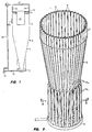
- the reference numeral 2 refers in general to the cyclone separator of the present invention which includes a roof section 4, a cylindrical section 6 with an inlet opening 6a, and a conically-shaped hopper section 8.
- a lower ring header 10 is disposed at the lower end of the hopper section 8 and an upper ring header 12 is disposed at the upper end of the roof section 4.
- the roof section 4 is connected to an inner barrel 13 in a conventional manner such as welding.
- the connection of the inner barrel 13 and the roof section 4 is gas-tight.
- the inner barrel 13 is aligned in a coaxial relationship with the cylindrical section 6.
- the lower portion of the inner barrel 13 extends into the cylindrical section 6.
- the upper portion of inner barrel 13 extends beyond the cyclone separator 2.
- the cylindrical section 6 and the hopper section 8 are formed by a group of continuous, spaced, constant diameter, parallel tubes 14.
- the tubes 14 are connected at their lower ends to the lower ring header 10 and span the entire length of the separator.
- the upper portion of the cylindrical section 6 is not shown in FIG. 2, it is understood that the remainder of cylindrical section 6 and the roof section 4 are also formed by the same group of tubes 14.
- a portion of the tubes 14 are bent away from the plane of cylindrical section 6 to form the inlet opening 6a (FIG. 1), which enables the gases containing the solid particles to be introduced into the annular chamber in a tangential direction.
- the tubes 14 are spaced apart by a plurality of fins 16 extending from diametrically opposed portions of each tube for the entire length of the tubes and connected to the tubes in any conventional manner, such as welding, to render the separator 2 gas-tight.
- the width of each fin 16 is constant in the cylindrical section 6, with the exception of the inlet opening 6a, and varies in the roof section 4 and the hopper section 8 as will be described.
- the tubes 14 extend generally horizontally from the upper ring header 12 in an inwardly direction and are then bent downwardly in a vertical direction.
- the tubes 14 are then bent outwardly in a generally horizontal direction to complete the roof section 4 and are then bent downwardly in a vertical direction to form the cylindrical section 6.
- At the lower portion of the cylindrical section the tubes 14 are bent inwardly at a slight angle to form the conically-shaped hopper section 8.
- the width of fins 16 necessarily decreases from the top to the bottom of conically-shaped hopper section 8, until the tubes 14 are in direct contact with one another, which negates the need for a fin.
- the tubes 14 are divided into two sets 14a and 14b.
- the tubes forming the set 14a extend the entire length of the hopper section 8 and are then bent radially outwardly and then downwardly into the lower ring header 10.
- the tubes forming the set 14b extend some distance down the hopper section 8 before being extracted, or bent radially outwardly, and are then bent downwardly toward the lower ring header 10.
- the lengths of both sets of tubes 14a and 14b are approximately equal from the upper ring header 12 to the lower ring header 10.
- the lower portion of the hopper section 8 is formed exclusively by the tubes of the set 14a, in combination with the fins 16.
- the tubes of the set 14a are bent radially outwardly at the bottom of the hopper section 8 and downwardly into the lower ring header 10.
- the tubes of the set 14b which have been extracted above this view, extend vertically into the lower ring header 10.
- FIG. 1 depicts the circulation system utilized with the separator 2 of the present invention.
- the circulation system is comprised of a natural-circulation steam drum 22, which is connected, via a pipe 24 and branch pipes 26 and 28, to the upper ring header 12.
- a down pipe 30 and branch pipe 32 connect the steam drum 22 to the lower ring header 10.
- the system circulates with water from the steam drum 22 conveyed by the down pipe 30 to the lower ring header 10 using the force of gravity and passes upwardly from the lower ring header 10 through the tubes 14 by natural convection, as will be described.
- separator 2 of the present invention is part of a boiler system including a fluidized bed reactor, or the like (not shown), disposed adjacent to the separator.
- the inlet opening 6a receives a hot gaseous mixture from the reactor which contain gases and entrained fine, solid, fuel particles from the fluidized bed.
- the inlet opening 6a is configured so as to introduce the hot gaseous mixture into the cylindrical section 6 in a tangential direction.
- the entrained solid particles are thus propelled, by centrifugal forces, against the inner wall of cylindrical section 6 where the solid particles collect and fall downwardly, due to the force of gravity, into the hopper section 8.
- the solid particles collected at the bottom of hopper section are directed to external equipment (not shown) for further use by means known in the art.
- the relatively clean gases remaining in the chamber are prevented from flowing upwardly by the roof section 4 and the connected inner barrel 13, and thus the gases are forced to enter the inner barrel 13 through its lower end.
- the gases pass through the length of the inner barrel 13 before exiting from the upper end of the inner barrel 13 and are directed to external equipment (not shown) for further use.
- Water, steam, or a combination thereof is passed from the steam drum 22, via pipes 30 and 32, into the lower ring header 10, and passes by natural convection upwardly through the tubes 14 of the hopper section 8, the cylindrical section 6 and inlet opening 6a, and the roof section 4.
- the heated water, steam, or combination thereof then passes from the roof section 4 into the upper ring header 12 and, via pipes 24, 26, and 28, back into steam drum 22.
- the circulating fluid thus maintains separator 2 at a relatively low temperature.
- the inner barrel 13 can be formed of water-cooled tubes in a manner similar to separator 2 and the inner barrel 13 can be connected to the flow circuit including the steam drum 22.
- a forced circulation system can be used instead of the natural circulation system described above in which case a pump 36 would be provided in the line 30 which receives the fluid from the drum 22 and pumps it to and through the branch conduit 32 and the tubes 14.
- the separator 40 includes a cylindrical section 42 and a conically-shaped lower hopper section 44.
- the entire separator 40, including the hopper section 44 is formed by a group of continuous, spaced, constant diameter, parallel tubes 46.
- the tubes 46 are spaced apart by a plurality of fins 48 extending from diametrically opposed portions of each tube for the entire lengths of the tubes and connected to the tube in any conventional manner, such as welding.
- the width of fins 48 necessarily decreases from top to bottom in the conically-shaped hopper section 44 until adjacent tubes are in direct contact with one another negating the need for a fin.
- each tube 46 is swaged at or above this area, which is referred to by the reference numeral 50.
- the reduced diameter segments of the tubes 46 extend the remaining length of the hopper section 44, are then bent radially outwardly at the bottom of the hopper section and are then bent downwardly into the lower ring header 52.
- FIG. 4 incorporates the same overall system and method of operation as illustrated in FIG. 1. and explained in the first embodiment, including all variations and modifications.
Applications Claiming Priority (2)
| Application Number | Priority Date | Filing Date | Title |
|---|---|---|---|
| US79751091A | 1991-11-21 | 1991-11-21 | |
| US797510 | 1991-11-21 |
Publications (2)
| Publication Number | Publication Date |
|---|---|
| EP0543564A1 true EP0543564A1 (fr) | 1993-05-26 |
| EP0543564B1 EP0543564B1 (fr) | 1997-01-15 |
Family
ID=25171034
Family Applications (1)
| Application Number | Title | Priority Date | Filing Date |
|---|---|---|---|
| EP92310317A Expired - Lifetime EP0543564B1 (fr) | 1991-11-21 | 1992-11-12 | Séparateur cyclone à refroidissement par eau |
Country Status (6)
| Country | Link |
|---|---|
| EP (1) | EP0543564B1 (fr) |
| JP (1) | JPH0741176B2 (fr) |
| KR (1) | KR100219906B1 (fr) |
| CA (1) | CA2082096A1 (fr) |
| ES (1) | ES2098458T3 (fr) |
| MX (1) | MX9206589A (fr) |
Cited By (2)
| Publication number | Priority date | Publication date | Assignee | Title |
|---|---|---|---|---|
| US6560658B2 (en) | 1999-03-04 | 2003-05-06 | Convolve, Inc. | Data storage device with quick and quiet modes |
| EP1533565A1 (fr) * | 2003-11-19 | 2005-05-25 | Siemens Aktiengesellschaft | Générateur de vapeur à passage unique |
Families Citing this family (2)
| Publication number | Priority date | Publication date | Assignee | Title |
|---|---|---|---|---|
| JP2913917B2 (ja) * | 1991-08-20 | 1999-06-28 | 株式会社日立製作所 | 記憶装置および記憶装置システム |
| KR100974432B1 (ko) | 2005-09-01 | 2010-08-05 | 현대중공업 주식회사 | 순환유동층 보일러용 수냉식 사이클론 |
Citations (6)
| Publication number | Priority date | Publication date | Assignee | Title |
|---|---|---|---|---|
| BE531648A (fr) * | ||||
| FR725554A (fr) * | 1931-11-03 | 1932-05-13 | Stirling Boiler Co Ltd | Perfectionnements aux chaudières aquatubulaires |
| DE739376C (de) * | 1940-01-17 | 1943-09-23 | Rheinmetall Borsig Ag | Wasserrohrdampferzeuger |
| EP0135664A2 (fr) * | 1983-08-31 | 1985-04-03 | GebràDer Sulzer Aktiengesellschaft | Passage de gaz vertical pour un échangeur de chaleur |
| US4746337A (en) * | 1987-07-06 | 1988-05-24 | Foster Wheeler Energy Corporation | Cyclone separator having water-steam cooled walls |
| US4944250A (en) * | 1989-03-30 | 1990-07-31 | Foster Wheeler Energy Corporation | Cyclone separator including a hopper formed by water-steam cooled walls |
-
1992
- 1992-11-04 CA CA002082096A patent/CA2082096A1/fr not_active Abandoned
- 1992-11-12 ES ES92310317T patent/ES2098458T3/es not_active Expired - Lifetime
- 1992-11-12 EP EP92310317A patent/EP0543564B1/fr not_active Expired - Lifetime
- 1992-11-16 MX MX9206589A patent/MX9206589A/es not_active IP Right Cessation
- 1992-11-18 JP JP4308821A patent/JPH0741176B2/ja not_active Expired - Fee Related
- 1992-11-20 KR KR1019920021825A patent/KR100219906B1/ko not_active IP Right Cessation
Patent Citations (8)
| Publication number | Priority date | Publication date | Assignee | Title |
|---|---|---|---|---|
| BE531648A (fr) * | ||||
| FR725554A (fr) * | 1931-11-03 | 1932-05-13 | Stirling Boiler Co Ltd | Perfectionnements aux chaudières aquatubulaires |
| DE739376C (de) * | 1940-01-17 | 1943-09-23 | Rheinmetall Borsig Ag | Wasserrohrdampferzeuger |
| EP0135664A2 (fr) * | 1983-08-31 | 1985-04-03 | GebràDer Sulzer Aktiengesellschaft | Passage de gaz vertical pour un échangeur de chaleur |
| US4746337A (en) * | 1987-07-06 | 1988-05-24 | Foster Wheeler Energy Corporation | Cyclone separator having water-steam cooled walls |
| US4746337B1 (fr) * | 1987-07-06 | 1992-08-11 | Foster Wheeler Energy Corp | |
| US4944250A (en) * | 1989-03-30 | 1990-07-31 | Foster Wheeler Energy Corporation | Cyclone separator including a hopper formed by water-steam cooled walls |
| US4944250B1 (fr) * | 1989-03-30 | 1992-07-14 | Foster Wheeler Energy Corp |
Cited By (5)
| Publication number | Priority date | Publication date | Assignee | Title |
|---|---|---|---|---|
| US6560658B2 (en) | 1999-03-04 | 2003-05-06 | Convolve, Inc. | Data storage device with quick and quiet modes |
| EP1533565A1 (fr) * | 2003-11-19 | 2005-05-25 | Siemens Aktiengesellschaft | Générateur de vapeur à passage unique |
| WO2005050089A1 (fr) * | 2003-11-19 | 2005-06-02 | Siemens Aktiengesellschaft | Generateur de vapeur en continu |
| US7516719B2 (en) | 2003-11-19 | 2009-04-14 | Siemens Aktiengesellschaft | Continuous steam generator |
| AU2004291619B2 (en) * | 2003-11-19 | 2009-09-10 | Siemens Aktiengesellschaft | Continuous steam generator |
Also Published As
| Publication number | Publication date |
|---|---|
| KR930009659A (ko) | 1993-06-21 |
| MX9206589A (es) | 1993-10-01 |
| CA2082096A1 (fr) | 1993-05-22 |
| KR100219906B1 (ko) | 1999-09-01 |
| ES2098458T3 (es) | 1997-05-01 |
| JPH05237418A (ja) | 1993-09-17 |
| JPH0741176B2 (ja) | 1995-05-10 |
| EP0543564B1 (fr) | 1997-01-15 |
Similar Documents
| Publication | Publication Date | Title |
|---|---|---|
| US4904286A (en) | Cyclone separator having water-steam cooled walls | |
| US4732113A (en) | Particle separator | |
| CA1329150C (fr) | Separateur-cyclone a tremie a parois refroidies a l'eau | |
| GB2172222A (en) | Water-cooled cyclone separator | |
| US5174799A (en) | Horizontal cyclone separator for a fluidized bed reactor | |
| US5203284A (en) | Fluidized bed combustion system utilizing improved connection between the reactor and separator | |
| JPS61502835A (ja) | 循環式流動床反応器内の煙道ガスから固形物を分離する装置 | |
| US5226936A (en) | Water-cooled cyclone separator | |
| US6863703B2 (en) | Compact footprint CFB with mechanical dust collector | |
| EP0399803A1 (fr) | Réacteur en lit fluidifié circulant utilisant des séparateurs intégrés à bras incurvés | |
| FI89203C (fi) | Foerbraenningsanlaeggning | |
| EP0402089A1 (fr) | Réacteur à lit fluidifié utilisant un séparateur des matières solides interne | |
| US5393315A (en) | Immersed heat exchanger in an integral cylindrical cyclone and loopseal | |
| EP0298671A2 (fr) | Séparateur cyclone à parois refroidies par eau ou vapeur | |
| EP0543564B1 (fr) | Séparateur cyclone à refroidissement par eau | |
| US6245300B1 (en) | Horizontal cyclone separator for a fluidized bed reactor | |
| JPH06229513A (ja) | 大規模流動床反応器 | |
| US5391211A (en) | Integral cylindrical cyclone and loopseal | |
| US4920924A (en) | Fluidized bed steam generating system including a steam cooled cyclone separator | |
| CA1323585C (fr) | Cyclone a parois refroidis par de la vapeur d'eau | |
| CA1327946C (fr) | Separateur cyclone a parois refroidies par jets d'eau | |
| JPH0435755A (ja) | サイクロン分離器 | |
| WO1988005336A1 (fr) | Reacteur a lit fluidise avec fluide circulant |
Legal Events
| Date | Code | Title | Description |
|---|---|---|---|
| PUAI | Public reference made under article 153(3) epc to a published international application that has entered the european phase |
Free format text: ORIGINAL CODE: 0009012 |
|
| AK | Designated contracting states |
Kind code of ref document: A1 Designated state(s): ES GB IT PT |
|
| 17P | Request for examination filed |
Effective date: 19931118 |
|
| 17Q | First examination report despatched |
Effective date: 19950803 |
|
| GRAG | Despatch of communication of intention to grant |
Free format text: ORIGINAL CODE: EPIDOS AGRA |
|
| GRAH | Despatch of communication of intention to grant a patent |
Free format text: ORIGINAL CODE: EPIDOS IGRA |
|
| GRAH | Despatch of communication of intention to grant a patent |
Free format text: ORIGINAL CODE: EPIDOS IGRA |
|
| GRAA | (expected) grant |
Free format text: ORIGINAL CODE: 0009210 |
|
| AK | Designated contracting states |
Kind code of ref document: B1 Designated state(s): ES GB IT PT |
|
| ITF | It: translation for a ep patent filed |
Owner name: 0403;06MIFING. C. GREGORJ S.P.A. |
|
| REG | Reference to a national code |
Ref country code: ES Ref legal event code: FG2A Ref document number: 2098458 Country of ref document: ES Kind code of ref document: T3 |
|
| PLBE | No opposition filed within time limit |
Free format text: ORIGINAL CODE: 0009261 |
|
| STAA | Information on the status of an ep patent application or granted ep patent |
Free format text: STATUS: NO OPPOSITION FILED WITHIN TIME LIMIT |
|
| 26N | No opposition filed | ||
| REG | Reference to a national code |
Ref country code: GB Ref legal event code: IF02 |
|
| PGFP | Annual fee paid to national office [announced via postgrant information from national office to epo] |
Ref country code: PT Payment date: 20021018 Year of fee payment: 11 |
|
| PG25 | Lapsed in a contracting state [announced via postgrant information from national office to epo] |
Ref country code: PT Free format text: LAPSE BECAUSE OF NON-PAYMENT OF DUE FEES Effective date: 20040531 |
|
| REG | Reference to a national code |
Ref country code: PT Ref legal event code: MM4A Free format text: LAPSE DUE TO NON-PAYMENT OF FEES Effective date: 20040531 |
|
| PGFP | Annual fee paid to national office [announced via postgrant information from national office to epo] |
Ref country code: GB Payment date: 20061016 Year of fee payment: 15 |
|
| PGFP | Annual fee paid to national office [announced via postgrant information from national office to epo] |
Ref country code: IT Payment date: 20061130 Year of fee payment: 15 |
|
| GBPC | Gb: european patent ceased through non-payment of renewal fee |
Effective date: 20071112 |
|
| PG25 | Lapsed in a contracting state [announced via postgrant information from national office to epo] |
Ref country code: GB Free format text: LAPSE BECAUSE OF NON-PAYMENT OF DUE FEES Effective date: 20071112 |
|
| PG25 | Lapsed in a contracting state [announced via postgrant information from national office to epo] |
Ref country code: IT Free format text: LAPSE BECAUSE OF NON-PAYMENT OF DUE FEES Effective date: 20071112 |
|
| PGFP | Annual fee paid to national office [announced via postgrant information from national office to epo] |
Ref country code: ES Payment date: 20111115 Year of fee payment: 20 |
|
| REG | Reference to a national code |
Ref country code: ES Ref legal event code: FD2A Effective date: 20140827 |
|
| PG25 | Lapsed in a contracting state [announced via postgrant information from national office to epo] |
Ref country code: ES Free format text: LAPSE BECAUSE OF EXPIRATION OF PROTECTION Effective date: 20121113 |