EP0542670A1 - Automatic dispenser for beverages - Google Patents
Automatic dispenser for beverages Download PDFInfo
- Publication number
- EP0542670A1 EP0542670A1 EP92810754A EP92810754A EP0542670A1 EP 0542670 A1 EP0542670 A1 EP 0542670A1 EP 92810754 A EP92810754 A EP 92810754A EP 92810754 A EP92810754 A EP 92810754A EP 0542670 A1 EP0542670 A1 EP 0542670A1
- Authority
- EP
- European Patent Office
- Prior art keywords
- vending machine
- machine according
- drive
- gear
- output shaft
- Prior art date
- Legal status (The legal status is an assumption and is not a legal conclusion. Google has not performed a legal analysis and makes no representation as to the accuracy of the status listed.)
- Granted
Links
- 235000013361 beverage Nutrition 0.000 title claims abstract description 29
- 239000000843 powder Substances 0.000 claims abstract description 30
- 235000020965 cold beverage Nutrition 0.000 claims abstract description 5
- XLYOFNOQVPJJNP-UHFFFAOYSA-N water Substances O XLYOFNOQVPJJNP-UHFFFAOYSA-N 0.000 claims description 26
- 230000005540 biological transmission Effects 0.000 claims description 10
- 230000008878 coupling Effects 0.000 claims description 9
- 238000010168 coupling process Methods 0.000 claims description 9
- 238000005859 coupling reaction Methods 0.000 claims description 9
- 238000002360 preparation method Methods 0.000 claims description 7
- 235000021260 warm beverage Nutrition 0.000 claims description 2
- 235000012171 hot beverage Nutrition 0.000 abstract description 3
- 235000019219 chocolate Nutrition 0.000 description 6
- 235000013353 coffee beverage Nutrition 0.000 description 6
- 235000016213 coffee Nutrition 0.000 description 5
- 244000269722 Thea sinensis Species 0.000 description 3
- YSXLJTGZMRNQSG-UHFFFAOYSA-L disodium;6-amino-5-[[2-[4-[2-[4-[2-[(2-amino-5-sulfonatonaphthalen-1-yl)diazenyl]phenyl]sulfonyloxyphenyl]propan-2-yl]phenoxy]sulfonylphenyl]diazenyl]naphthalene-1-sulfonate Chemical compound [Na+].[Na+].C1=CC=C2C(N=NC3=CC=CC=C3S(=O)(=O)OC3=CC=C(C=C3)C(C)(C=3C=CC(OS(=O)(=O)C=4C(=CC=CC=4)N=NC=4C5=CC=CC(=C5C=CC=4N)S([O-])(=O)=O)=CC=3)C)=C(N)C=CC2=C1S([O-])(=O)=O YSXLJTGZMRNQSG-UHFFFAOYSA-L 0.000 description 2
- 235000020278 hot chocolate Nutrition 0.000 description 2
- 235000014347 soups Nutrition 0.000 description 2
- 235000013616 tea Nutrition 0.000 description 2
- 244000046052 Phaseolus vulgaris Species 0.000 description 1
- 235000010627 Phaseolus vulgaris Nutrition 0.000 description 1
- 241000533293 Sesbania emerus Species 0.000 description 1
- 230000015556 catabolic process Effects 0.000 description 1
- 230000002860 competitive effect Effects 0.000 description 1
- 238000011109 contamination Methods 0.000 description 1
- 230000007547 defect Effects 0.000 description 1
- 230000002950 deficient Effects 0.000 description 1
- 230000001419 dependent effect Effects 0.000 description 1
- 238000011161 development Methods 0.000 description 1
- 230000018109 developmental process Effects 0.000 description 1
- 235000015114 espresso Nutrition 0.000 description 1
- 230000007257 malfunction Effects 0.000 description 1
- 239000008267 milk Substances 0.000 description 1
- 210000004080 milk Anatomy 0.000 description 1
- 235000013336 milk Nutrition 0.000 description 1
- 230000008092 positive effect Effects 0.000 description 1
- 238000003825 pressing Methods 0.000 description 1
- 230000004800 psychological effect Effects 0.000 description 1
- 238000005086 pumping Methods 0.000 description 1
Images


Classifications
-
- A—HUMAN NECESSITIES
- A47—FURNITURE; DOMESTIC ARTICLES OR APPLIANCES; COFFEE MILLS; SPICE MILLS; SUCTION CLEANERS IN GENERAL
- A47J—KITCHEN EQUIPMENT; COFFEE MILLS; SPICE MILLS; APPARATUS FOR MAKING BEVERAGES
- A47J31/00—Apparatus for making beverages
-
- A—HUMAN NECESSITIES
- A47—FURNITURE; DOMESTIC ARTICLES OR APPLIANCES; COFFEE MILLS; SPICE MILLS; SUCTION CLEANERS IN GENERAL
- A47J—KITCHEN EQUIPMENT; COFFEE MILLS; SPICE MILLS; APPARATUS FOR MAKING BEVERAGES
- A47J31/00—Apparatus for making beverages
- A47J31/40—Beverage-making apparatus with dispensing means for adding a measured quantity of ingredients, e.g. coffee, water, sugar, cocoa, milk, tea
- A47J31/401—Beverage-making apparatus with dispensing means for adding a measured quantity of ingredients, e.g. coffee, water, sugar, cocoa, milk, tea whereby the powder ingredients and the water are delivered to a mixing bowl
-
- G—PHYSICS
- G07—CHECKING-DEVICES
- G07F—COIN-FREED OR LIKE APPARATUS
- G07F13/00—Coin-freed apparatus for controlling dispensing or fluids, semiliquids or granular material from reservoirs
- G07F13/06—Coin-freed apparatus for controlling dispensing or fluids, semiliquids or granular material from reservoirs with selective dispensing of different fluids or materials or mixtures thereof
- G07F13/065—Coin-freed apparatus for controlling dispensing or fluids, semiliquids or granular material from reservoirs with selective dispensing of different fluids or materials or mixtures thereof for drink preparation
Definitions
- the invention relates to a vending machine as described in the preamble of claim 1.
- Vending machines of this type have been known for a long time and are used in various places for the optional preparation of drinks, in particular coffee, tea, chocolate (Ovaltine), and soups.
- drinks in particular coffee, tea, chocolate (Ovaltine), and soups.
- tea and chocolate drinks there is usually also the option of choosing between a cold and warm drink.
- the drink is only prepared after inserting money, a chip or after validating a tax card.
- versions are also known in which the drink is prepared free of charge at the push of a button.
- Vending machines of this type must meet various criteria at the same time. On the one hand, they have to be able to be produced inexpensively, because there is strong competitive pressure in this area, and on the other hand, they have to be reliable, because a breakdown of the vending machine leads to user displeasure and a loss of profit for the operator. Furthermore, these machines should be constructed in such a way that a malfunction can be rectified quickly and easily. For example, wear parts should be easily accessible in the vending machine be. Furthermore, the vending machine should be constructed in such a way that the parts subject to contamination can be cleaned by the operating personnel in a short time in such a way that the vending machine meets the hygienic requirements.
- vending machine meets any expansion requests regarding the selection of beverages, that is, if possible, it should be constructed in such a way that additional types of beverages can be offered in a simple manner.
- the selection and preparation of a drink with such a vending machine takes place approximately as follows: the user selects the desired drink using a selection button on the vending machine. The cup is then positioned to receive the drink; then the water pump is turned on. When a hot beverage is selected, the pumped water passes through a hot water heater and a mixing unit and then flows into the cup. When a cold drink is selected, a bypass is activated instead of the hot water heater. When the water passes through the mixing unit, the corresponding amount of beverage powder (tea, soup, chocolate, coffee and / or milk powder) conveyed by a conveying element of the storage container is added to it.
- beverage powder tea, soup, chocolate, coffee and / or milk powder
- this button press is registered by a built-in microprocessor control and the corresponding program is started.
- a corresponding software program is available for each drink.
- the built-in control unit is aware that 2 dl of hot water and 10 grams of powdered beverage are required to prepare it.
- the chocolate powder is metered in in such a way that the required amount of powder is controlled via the switch-on time of the powder conveyor.
- the pump for pumping the water must be switched on for approx. 20 seconds. The time period is therefore relatively long since the water is heated by means of a continuous flow heater and therefore cannot flow through it as quickly as desired.
- the dosing time for the chocolate powder is estimated to be about 6 seconds.
- the powders are mixed into the hot water running through (or with cold drinks the cold water) so that when the chocolate drink enters the cup the drink is already well mixed.
- the powder metering time cannot simply be extended, since otherwise an espresso is prepared, in which much less water is used for an equal amount of drink powder , the opposite would happen, namely that the necessary coffee powder could not be dissolved in the available hot water while it was flowing through.
- the quantity of beverage powder conveyed per unit of time cannot be varied either, since otherwise a much more complex control of the drive motor would have to be used.
- the Powder conveyors each have a separate drive motor with a gearbox, so that in the case of an automatic beverage machine which, for example, provides four different types of drinks, four drive motors and associated gearboxes are also required.
- a particularly advantageous embodiment of the vending machine can be achieved in that the beverage powder is metered in at intervals through the water.
- the screw conveyor In order to couple the screw conveyor to the drive shaft, only one electro magnet needs to be switched on and off. This makes it possible to realize batch-wise metering in the first place, since the relatively large mass inertia, which a motor with the corresponding coupled mechanics does not come into play here and therefore an intermittent delivery and metering is possible at short intervals.
- a further advantageous embodiment of the vending machine can be achieved in that the storage containers and the gears assigned to the storage containers are constructed in a modular manner with the electromagnets. This makes it possible to retrofit such a vending machine, i.e. that another or more additional storage containers with the corresponding conveyor units can be used if there is still space in the housing.
- resilient connections can be provided, which have the advantage that inevitable axial and radial offsets are absorbed by these connections.
- modules which essentially consist of an electro magnet, an axially displaceable shaft with attached gear and a drive worm, can be replaced quickly and easily, both the individual parts and the entire unit.
- the housing 1 shows a simplified representation of the basic structure of the drinks machine according to the invention in longitudinal section.
- the housing 1 has a fastening plate 14 to which, in addition to other parts, a hot water heater 2, a pump 3 and a drive motor 11 are fastened.
- a fastening rail 40 is attached to the end of the mounting plate 14, on which individual gear modules 10 are suspended.
- a cold water container 5 and several beverage powder storage containers 7 are accommodated in the upper part of the housing 1.
- the housing 1 also houses a control element 28 for controlling the course of the beverage preparation.
- a coffee bean storage container 13 with a coffee grinder (not shown) for preparing bean coffee.
- a coffee grinder for preparing bean coffee.
- the necessary connecting hoses are not shown.
- a common drive motor 11 and three gear modules 10, each associated with a beverage powder storage container 7, are provided for optionally driving the same.
- the drive shafts of all three transmission modules 10 are aligned, i.e. lie on the same axis.
- the drive motor 11 has a drive shaft 12 which is likewise aligned with the drive shafts of the transmission modules 10 and which is connected by a spring-elastic connecting element 20, e.g. a spiral spring is coupled to the drive shaft 29 and thus to the drive worm 24 of a first gear 26 forming part of a gear module 10.
- the drive shaft 29 and thus the drive worm 24 of the next transmission is then in turn coupled by means of a connecting element 20 to the first drive worm 24 and the third drive worm 24 to the second drive worm 24 likewise by means of a connecting element 20, so that all drive worms 24 are interconnected and with the drive motor 11 are mechanically connected.
- the transmission 26 of the middle of the three transmission modules 10 shown is shown in the engaged state. This means that in this position the drive motor 11 drives the screw conveyor 6 of the middle beverage powder storage container 7 via the middle gear 26, the drive screws 24 of the other two gears running idle.
- the gear module 10 has a support frame 31 in which an axially displaceable output shaft 22 and, at a right angle thereto, the drive shaft 29 with the drive worm 24 are rotatably mounted. Coaxial to the output shaft 22, an electromagnet 21 is attached to the frame 31.
- the output shaft 22 carries a worm wheel 23 and has a coupling part 25 at one end. At the other end, the output shaft 22 is operatively connected to the electromagnet 21. If the electromagnet 21 is energized, the output shaft 22 is displaced in the direction of the screw conveyor 6.
- the worm wheel 23 engages in the drive worm 24 of the drive shaft 29, and at the same time the output shaft 22 is coupled to the conveyor worm 6 by the coupling part 25.
- the output shaft 22 tends to return to the rest position (disengaged position); this means that the output shaft 22 remains coupled only as long as the electromagnet 21 is also live.
- FIG. 5 shows two transmission modules 10.
- the output shaft 22 with the worm wheel 23 is rotatably supported in the frame 31.
- the electromagnet also attached to the frame 31 21 is operatively connected to the output shaft 22.
- the electromagnet 21 is energized and thereby pushes the output shaft 22 against the mounting rail 40.
- the worm wheel 23 couples into the drive worm 24 and the coupling part 25 into the feed screw 6 (not shown here).
- the mechanical connection between the drive screw 24 and the screw conveyor 6 is thus established.
- the electromagnet 21 On the left of the two shown transmission modules 10, the electromagnet 21 is shown in the rest position. Characterized in that for coupling the drive screws 24 spring-elastic connecting elements 20, e.g. Spiral springs can be used to compensate for both radial and axial tolerances.
- the modules 10 are hooked into openings in the fastening rail 40 by means of guide lugs 42 and are snapped into the fastening rail 40 by means of resilient latching hooks, not shown here.
Landscapes
- Engineering & Computer Science (AREA)
- Food Science & Technology (AREA)
- Physics & Mathematics (AREA)
- General Physics & Mathematics (AREA)
- Apparatus For Making Beverages (AREA)
- Beverage Vending Machines With Cups, And Gas Or Electricity Vending Machines (AREA)
- Soil Working Implements (AREA)
- Eye Examination Apparatus (AREA)
- Formation And Processing Of Food Products (AREA)
- Control Of Vending Devices And Auxiliary Devices For Vending Devices (AREA)
Abstract
Description
Die Erfindung betrifft einen Getränkeautomaten, wie er im Oberbegriff des Patentanspruchs 1 beschrieben ist.The invention relates to a vending machine as described in the preamble of
Getränkeautomaten dieser Art sind seit längerem bekannt und werden an den verschiedensten Orten zur wahlweisen Zubereitung von Getränken, insbesondere Kaffee, Tee, Schokolade (Ovomaltine), sowie Suppen eingesetzt. Bei den Tee- und Schokolade-Getränken besteht zudem meist die Möglichkeit, zwischen einem Kalt- und Warmgetränk zu wählen. Das Getränk wird in der Regel erst nach Einwurf von Geld, einem Jeton oder nach Entwerten einer Taxcard zubereitet. Es sind aber auch Ausführungen bekannt, bei denen das Getränk auf gratis auf Tastendruck zubereitet wird.Vending machines of this type have been known for a long time and are used in various places for the optional preparation of drinks, in particular coffee, tea, chocolate (Ovaltine), and soups. In the case of tea and chocolate drinks, there is usually also the option of choosing between a cold and warm drink. As a rule, the drink is only prepared after inserting money, a chip or after validating a tax card. However, versions are also known in which the drink is prepared free of charge at the push of a button.
Getränkeautomaten dieser Art müssen verschiedene Kriterien zugleich erfüllen. Zum einen müssen sie kostengünstig hergestellt werden können, da ein starker Konkurrenzdruck auf diesem Gebiet besteht, und zum andern müssen sie zuverlässig sein, da ein Ausfall des Getränkeautomaten den Unmut der Benutzer sowie einen Ertragsausfall des Betreibers mit sich bringt. Im weiteren sollen diese Automaten so aufgebaut sein, dass eine Betriebsstörung schnell und einfach behoben werden kann. So sollen z.B. die Verschleissteile gut zugänglich im Getränkeautomaten angebracht sein. Im weiteren sollte der Getränkeautomat so aufgebaut sein, dass die der Verschmutzung unterliegenden Teile vom Bedienpersonal in kurzer Zeit derart gereinigt werden können, dass der Automat den hygienischen Anforderungen gerecht wird.Vending machines of this type must meet various criteria at the same time. On the one hand, they have to be able to be produced inexpensively, because there is strong competitive pressure in this area, and on the other hand, they have to be reliable, because a breakdown of the vending machine leads to user displeasure and a loss of profit for the operator. Furthermore, these machines should be constructed in such a way that a malfunction can be rectified quickly and easily. For example, wear parts should be easily accessible in the vending machine be. Furthermore, the vending machine should be constructed in such a way that the parts subject to contamination can be cleaned by the operating personnel in a short time in such a way that the vending machine meets the hygienic requirements.
Eine weitere Forderung ist, dass der Getränkeautomat allfälligen Erweiterungswünschen bezüglich der Getränkeauswahl gerecht wird, das heisst, dass er wenn möglich so aufgebaut sein soll, dass auf einfache Art und Weise zusätzliche Getränkesorten angeboten werden können.Another requirement is that the vending machine meets any expansion requests regarding the selection of beverages, that is, if possible, it should be constructed in such a way that additional types of beverages can be offered in a simple manner.
Die Auswahl und Zubereitung eines Getränks mit einem derartigen Getränkeautomaten geht in etwa folgendermassen vor sich: Der Benutzer wählt das von ihm gewünschte Getränk mittels einer Anwahltaste am Getränkeautomat aus. Anschliessend wird der Becher zur Aufnahme des Getränks in Stellung gebracht; dann wird die Wasserpumpe eingeschaltet. Das geförderte Wasser durchläuft bei Wahl eines Heissgetränks einen Heisswasserbereiter sowie eine Mischeinheit und fliesst dann schliesslich in den Becher ein. Bei Wahl eines Kaltgetränks tritt anstelle des Heiswasserbereiters ein Bypass in Aktion. Beim Durchlaufen des Wassers durch die Mischeinheit wird diesem die entsprechende, durch ein Förderorgan des Vorratsbehälters geförderte Menge Getränkepulver (Tee, Suppe, Schokolade, Kaffee und/oder Milchpulver) beigemischt.The selection and preparation of a drink with such a vending machine takes place approximately as follows: the user selects the desired drink using a selection button on the vending machine. The cup is then positioned to receive the drink; then the water pump is turned on. When a hot beverage is selected, the pumped water passes through a hot water heater and a mixing unit and then flows into the cup. When a cold drink is selected, a bypass is activated instead of the hot water heater. When the water passes through the mixing unit, the corresponding amount of beverage powder (tea, soup, chocolate, coffee and / or milk powder) conveyed by a conveying element of the storage container is added to it.
Wählt nun der Benutzer mittels Tastendruck am Bedienteil ein bestimmtes Getränk aus, so wird dieser Tastendruck von einer eingebauten Mikroprozessor-Steuerung registriert und das entsprechende Programm wird gestartet. Für jedes Getränk ist ein entsprechendes Software-Programm vorhanden. Wird nun beispielsweise eine heisse Schokolade gewünscht, so ist der eingebauten Steuerung bekannt, dass für deren Zubereitung beispielsweise 2 dl Heiss-Wasser sowie 10 Gramm Getränkepulver notwendig sind. Die Zudosierung des Schokoladenpulvers wird aus Kostengründen derart realisiert, dass die notwendige Pulver-Menge über die Einschaltzeit des Pulverförderers gesteuert wird. Für die Zubereitung einer heissen Schokolade muss die Pumpe zum Fördern des Wassers ca. 20 Sekunden eingeschaltet werden. Die Zeitdauer ist deshalb relativ hoch, da das Wasser mittels eines Durchlauferhitzers erwärmt wird und diesen daher nicht beliebig schnell durchfliessen kann. Die Zudosierungszeit für das Schokoladenpulver ist mit ca. 6 Sekunden zu veranschlagen. Die Pulver werden dem durchlaufenden Heisswasser (oder bei Kaltgetränken dem Kaltwasser) zugemischt, so dass beim Einlaufen des Schokoladen-Getränks in den Becher das Getränk bereits gut durchmischt ist.If the user now selects a particular drink by pressing a button on the control panel, this button press is registered by a built-in microprocessor control and the corresponding program is started. A corresponding software program is available for each drink. If, for example, hot chocolate is now desired, the built-in control unit is aware that 2 dl of hot water and 10 grams of powdered beverage are required to prepare it. For cost reasons, the chocolate powder is metered in in such a way that the required amount of powder is controlled via the switch-on time of the powder conveyor. To prepare hot chocolate, the pump for pumping the water must be switched on for approx. 20 seconds. The time period is therefore relatively long since the water is heated by means of a continuous flow heater and therefore cannot flow through it as quickly as desired. The dosing time for the chocolate powder is estimated to be about 6 seconds. The powders are mixed into the hot water running through (or with cold drinks the cold water) so that when the chocolate drink enters the cup the drink is already well mixed.
Da die Zudosierungszeit des Pulvers zum Heisswasser wesentlich kürzer als die Durchlaufzeit des Wassers ist, sieht es für den Benutzer in der Praxis so aus, dass nur während ca. 8 Sekunden ein sichtbar eingefärbtes Schokoladengetränk in den Becher einfliesst, und dass während der restlichen 12 Sekunden bloss heisses Wasser einfliesst. Dies hat einerseits psychologische Auswirkungen, da der Benutzer das Gefühl hat, dass er für sein Geld bloss 50% vom gewünschten Getränk erhält, und zum anderen kommt es vor, dass einzelne Benutzer den Becher vor Ende des Heisswasserauslaufs wegziehen, da sie das Gefühl haben, dass das Wasser nicht mehr zum eigentlichen Getränke-Aufbereitungs-Vorgang dazugehört. Dies hat natürlich den Nachteil, dass das in dem Getränkeautomaten vorhandene Auffangbecken für "Restwasser" sehr schnell gefüllt ist, und dass es daher zum Überlaufen dieses Auffangbeckens kommen kann.Since the time to add the powder to the hot water is considerably shorter than the throughput time of the water, it looks to the user in practice that a visibly colored chocolate drink only flows into the cup for about 8 seconds, and that only hot water flows in for the remaining 12 seconds. On the one hand, this has psychological effects, since the user feels that they only get 50% of the desired drink for their money, and on the other hand, it happens that individual users pull the cup away before the hot water spout ends, because they have the feeling that that the water is no longer part of the actual beverage preparation process. This has the disadvantage, of course, that the catch basin for "residual water" in the drinks machine is filled very quickly, and that this catch basin can therefore overflow.
Damit das zubereitete Schokoladengetränk während der ganzen "Einlaufdauer" als sichtlich mit Pulver durchsetztes Getränk in den Becher einfliesst, kann nicht einfach die Pulverzudosierungszeit verlängert werden, da sonst bei der Zubereitung eines Espressos, bei dem ja viel weniger Wasser auf eine gleich grosse Menge Getränkepulver kommt, das Gegenteil passieren würde, indem nämlich das notwendige Kaffeepulver nicht in dem zur Verfügung stehenden Heisswasser während dessen Durchlaufen aufgelöst werden könnte. Die pro Zeiteinheit geförderte Getränkepulvermenge kann auch nicht variiert werden, da sonst eine wesentlich aufwendigere Steuerung des Antriebsmotors eingesetzt werden müsste.So that the prepared chocolate drink flows into the cup as a clearly powdered drink during the entire "running-in period", the powder metering time cannot simply be extended, since otherwise an espresso is prepared, in which much less water is used for an equal amount of drink powder , the opposite would happen, namely that the necessary coffee powder could not be dissolved in the available hot water while it was flowing through. The quantity of beverage powder conveyed per unit of time cannot be varied either, since otherwise a much more complex control of the drive motor would have to be used.
Bei den bisher bekannten Getränkeautomaten ist zum Antrieb der Pulverfördermittel jeweils ein separater Antriebsmotor mit Getriebe vorhanden, so dass bei einem Getränkeautomaten, welcher z.B. vier verschiedene Getränkesorten zur Auswahl stellt, auch vier Antriebsmotoren samt zugeordneten Getrieben erforderlich sind.In the previously known vending machines, the Powder conveyors each have a separate drive motor with a gearbox, so that in the case of an automatic beverage machine which, for example, provides four different types of drinks, four drive motors and associated gearboxes are also required.
Es ist daher die Aufgabe der Erfindung, die vorerwähnten Nachteile zu vermeiden und einen Getränkeautomaten gemäss Oberbegriff des Patentanspruchs 1 so weiterzuentwickeln, dass er mit weniger Aufwand als bisher und damit preisgünstiger hergestellt werden kann und dass für den Betreiber des Getränkeautomaten die Möglichkeit besteht, Verschleissteile sowie defekte Bauteile auf einfache Art selber auszuwechseln.It is therefore the object of the invention to avoid the aforementioned disadvantages and to further develop a drinks machine according to the preamble of
Gemäss der Erfindung wird diese Aufgabe durch die im kennzeichnenden Teil des Patentanspruchs 1 definierten Merkmale gelöst. Weiterbildungen und besondere Ausführungsarten sind in den abhängigen Ansprüchen 2 bis 13 beschrieben.According to the invention, this object is achieved by the features defined in the characterizing part of
Eine besonders vorteilhafte Ausführungsform des Getränkeautomaten kann dadurch erreicht werden, dass das Getränkepulver beim Durchlaufen des Wassers in Intervallen zudosiert wird. Um die Förderschnecke an der Antriebs-Welle einzukuppeln, braucht nur jeweils ein Elektro-Magnet ein- und ausgeschaltet zu werden. Dadurch ist es überhaupt erst möglich, eine schubweise Zudosierung zu realisieren, da die relativ grosse Massenträgheit, welche ein Motor mit der entsprechenden angekoppelten Mechanik hat, hier nicht zum Tragen kommt und daher ein intervallmässiges Fördern und Zudosieren in kurzen Zeitabständen möglich ist.A particularly advantageous embodiment of the vending machine can be achieved in that the beverage powder is metered in at intervals through the water. In order to couple the screw conveyor to the drive shaft, only one electro magnet needs to be switched on and off. This makes it possible to realize batch-wise metering in the first place, since the relatively large mass inertia, which a motor with the corresponding coupled mechanics does not come into play here and therefore an intermittent delivery and metering is possible at short intervals.
Eine weitere vorteilhafte Ausführungsform des Getränkeautomaten kann dadurch erreicht werden, dass die Vorratsbehälter sowie die den Vorratsbehältern zugeordneten Getriebe mit den Elektromagneten modular aufgebaut sind. Dadurch ist es möglich, einen solchen Getränkeautomaten nachträglich aufzurüsten, d.h. dass noch ein weiterer oder mehrere zusätzliche Vorratsbehälter mit den entsprechenden Fördereinheiten zusätzlich eingesetzt werden können, wenn im Gehäuse noch Platz vorhanden ist.A further advantageous embodiment of the vending machine can be achieved in that the storage containers and the gears assigned to the storage containers are constructed in a modular manner with the electromagnets. This makes it possible to retrofit such a vending machine, i.e. that another or more additional storage containers with the corresponding conveyor units can be used if there is still space in the housing.
Um die Antriebsschnecken der einzelnen Fördereinheiten zu koppeln, können federelastische Verbindungen vorgesehen sein, welche den Vorteil haben, dass zwangsläufig vorhandene achsiale wie radiale Versätze von diesen Verbindungen aufgenommen werden.In order to couple the drive screws of the individual conveyor units, resilient connections can be provided, which have the advantage that inevitable axial and radial offsets are absorbed by these connections.
Ein weiterer Vorteil des modularen Aufbaus besteht darin, dass sowohl für einfache Getränkeautomaten, mit welchen z. B. "nur" Kaffeegetränke zubereitet werden können, wie auch für aufwendigere Getränkeautomaten, welche durchaus drei oder mehr verschiedene Getränkesorten zur Auswahl stellen, dieselben Module verwendet werden. Ausserdem besteht ein weiterer wesentlicher Vorteil darin, dass bei einem Defekt oder bei entsprechender Abnützung die Module, welche im wesentlichen aus einem Elektro-Magneten, einer achsial verschiebbaren Welle mit aufgesetztem Zahnrad sowie einer Antriebsschnecke bestehen, schnell und einfach ausgetauscht werden können, und zwar sowohl die einzelnen Teile wie auch die gesamte Einheit.Another advantage of the modular structure is that both for simple drinks machines, with which, for. B. "only" coffee beverages can be prepared, as well as for more elaborate vending machines, which definitely have three or more different types of drinks to choose from, the same modules are used. In addition, there is a further significant advantage that in the event of a defect or a corresponding one Wear the modules, which essentially consist of an electro magnet, an axially displaceable shaft with attached gear and a drive worm, can be replaced quickly and easily, both the individual parts and the entire unit.
Ein Ausführungsbeispiel des erfindungsgemässen Getränkeautomaten wird im folgenden anhand der beiliegenden Zeichnungen näher erläutert. In den Zeichnungen zeigt:
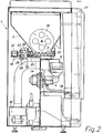
- Fig.1 Einen Längsschnitt durch den Getränkeautomaten;
- Fig.2 Einen querschnitt durch den Getränkeautomaten;
- Fig.3 Einen Schnitt entlang einer horizontalen Ebene durch den Getränkeautomaten;
- Fig.4 Einen vergrösserten Ausschnitt aus der Fig.2; und
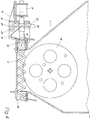
- Fig.5 Eine vergrösserte Darstellung der Module.
- 1 shows a longitudinal section through the vending machine;
- Fig.2 A cross section through the vending machine;
- 3 shows a section along a horizontal plane through the vending machine;
- 4 shows an enlarged detail from FIG. 2; and
- Fig.5 An enlarged view of the modules.
Die Fig.1 zeigt in vereinfachter Darstellung den prinzipiellen Aufbau des erfindungsgemässen Getränkeautomaten im Längsschnitt. Das Gehäuse 1 weist eine Befestigungsplatte 14 auf, an welcher, nebst anderen Teilen, ein Heisswasserbereiter 2, eine Pumpe 3, sowie ein Antriebsmotor 11 befestigt sind. Am oberen Ende der Befetigungsplatte 14 ist eine Befestigungsschiene 40 angebracht, an welcher einzelne Getriebemodule 10 eingehängt sind. Ein Kaltwasserbehälter 5 sowie mehrere Getränkepulver-Vorratsbehälter 7 sind im oberen Teil des Gehäuses 1 untergebracht. Darüberhinaus beherbergt das Gehäuse 1 auch ein Steuerorgan 28 zur Steuerung des Ablaufs der Getränkezubereitung.1 shows a simplified representation of the basic structure of the drinks machine according to the invention in longitudinal section. The
Ausserdem kann noch ein Kaffeebohnen-Vorratsbehälter 13 mit einem Kaffeemahlwerk (nicht abgebildet) zur Zubereitung von Bohnen-Kaffee vorhanden sein. Der besseren Übersicht wegen, sind die notwendigen Verbindungsschläuche nicht eingezeichnet.In addition, there can also be a coffee
Aus der Querschnittsdarstellung gemäss Fig.2 ist der Getränkepulver-Vorratsbehälter 7 mit einem darin angeordneten Mischrad 16 ersichtlich, welches das problemlose Fördern des im Vorratsbehälter 7 gespeicherten Getränkepulvers durch eine Förderschnecke 6 unterstützt. Das durch die Förderschnecke 6 geförderte Getränkepulver öffnet eine Klappe 15 so, dass das Getränkepulver durch die entstehende Öffnung in einen Trichter 9 einer Mischeinheit 4 fällt und in dieser Mischeinheit dann mit dem durchfliessenden Wasser vermischt wird, um anschliessend durch eine Leitung 18 in einen Becher (nicht dargestellt) einfliessen zu können. Durch eine Absaugvorrichtung 30 wird verhindert, dass der beim Zubereiten von Heissgetränken entstehende Dampf das Getränkepulver im Bereich der Klappe 15 verklebt. Röhren 17 dienen als Vorratsbehälter für die Getränke-Becher.2 shows the beverage
Beim vorliegenden Ausführungsbeispiel sind drei Getränkepulver-Vorratsbehälter 7 vorhanden, die je eine Förderschnecke 6 aufweisen. Zum wahlweisen Antrieb derselben ist gemäss Fig.3 ein gemeinsamer Antriebsmotor 11 und drei je einem Getränkepulver-Vorratsbehälter 7 zugeordnete Getriebemodule 10 vorgesehen. Die Antriebswellen aller drei Getriebemodule 10 fluchten, d.h. liegen auf derselben Achse. Der Antriebsmotor 11 weist eine ebenfalls mit den Antriebswellen der Getriebemodule 10 fluchtend angeordnete Antriebswelle 12 auf, welche durch ein federelastisches Verbindungselement 20, z.B. eine Spiralfeder, mit der Antriebswelle 29 und damit mit der Antriebsschnecke 24 eines ersten, einen Teil eines Getriebemoduls 10 bildenden Getriebes 26 gekoppelt ist. Die Antriebswelle 29 und damit die Antriebsschnecke 24 des nächsten Getriebes ist dann wiederum mittels eines Verbindungselements 20 mit der ersten Antriebsschnecke 24 und die dritte Antriebsschnecke 24 mit der zweiten Antriebsschnecke 24 ebenfalls mittels eines Verbindungselements 20 gekoppelt, so dass alle Antriebsschnecken 24 untereinander und mit dem Antriebsmotor 11 mechanisch verbunden sind.In the present exemplary embodiment, there are three beverage
Das Getriebe 26 des mittleren der drei dargestellten Getriebemodule 10 ist in eingerastetem Zustand dargestellt. Das bedeutet, dass in dieser Position der Antriebsmotor 11 über das mittlere Getriebe 26 die Förderschnecke 6 des mittleren Getränkepulver-Vorratsbehälters 7 antreibt, wobei die Antriebsschnecken 24 der beiden anderen Getriebe leer mitlaufen.The
Aus der Fig. 4 ist der Aufbau und die Funktionsweise des Getriebes 26 in Verbindung mit der Förderschnecke 6 ersichtlich. Das Getriebemodul 10 weist einen Tragrahmen 31 auf, in welchem eine achsial verschiebbare Abtriebswelle 22 sowie in rechtem Winkel dazu die Antriebswelle 29 mit der Antriebsschnecke 24 drehbar gelagert sind. Koachsial zur Abtriebswelle 22 ist ein Elektromagnet 21 am Rahmen 31 befestigt. Die Abtriebswelle 22 trägt ein Schneckenrad 23 und besitzt an ihrem einen Ende einen Kupplungsteil 25. Am anderen Ende steht die Abtriebswelle 22 mit dem Elektromagneten 21 in Wirkverbindung. Wird der Elektromagnet 21 unter Strom gesetzt, so wird die Abtriebswelle 22 in Richtung der Förderschnecke 6 verschoben. Dadurch greift das Schneckenrad 23 in die Antriebsschnecke 24 der Antriebswelle 29 ein, und gleichzeitig wird die Abtriebswelle 22 durch den Kupplungsteil 25 an die Förderschnecke 6 angekuppelt. Dadurch besteht nun eine antriebsmässige Verbindung zwischen der Antriebswelle 29 des Getriebes 26 und der Förderschnecke 6. Durch die Vorspannkraft einer Feder 19 hat die Abtriebswelle 22 das Bestreben, in die Ruhestellung (Ausrastposition) zurückzukehren; das bedeutet, dass die Abtriebswelle 22 nur solange zugekuppelt bleibt, wie der Elektromagnet 21 auch unter Strom steht.4 shows the structure and the mode of operation of the
In Fig.5 sind zwei Getriebemodule 10 dargestellt. Die Abtriebswelle 22 mit dem Schneckenrad 23 ist jeweils drehbar im Rahmen 31 gelagert. Der ebenfalls am Rahmen 31 befestigte Elektromagnet 21 steht mit der Abtriebswelle 22 in Wirkverbindung. Beim rechts abgebildeten Getriebemodul 10 steht der Elektromagnet 21 unter Strom und schiebt dadurch die Abtriebswelle 22 gegen die Befestigungsschiene 40. Dadurch kuppelt das Schneckenrad 23 in die Antriebsschnecke 24 und das Kupplungsteil 25 in die (hier nicht dargestellte) Förderschnecke 6 ein. Damit ist die mechanische Verbindung zwischen der Antriebsschnecke 24 und der Förderschnecke 6 hergestellt.5 shows two
Beim linken der beiden abgebildeten Getriebemodule 10 ist der Elektromagnet 21 in Ruhestellung dargestellt. Dadurch, dass zur Kopplung der Antriebsschnecken 24 federelastische Verbindungselemente 20, z.B. Spiralfedern, zum Einsatz kommen, können sowohl radiale wie auch achsiale Toleranzen ausgeglichen werden. Die Module 10 sind mittels Führungsnasen 42 in Öffnungen der Befestigungsschiene 40 eingehängt und mittels federnden, hier nicht näher dargestellten Rasthaken in der Befestigungsschiene 40 eingerastet.On the left of the two shown
Dadurch, dass zum Fördern des Getränkepulvers nur noch ein Antriebsmotor vorhanden ist, wird einerseits der Preis eines erfindungsgemässen Getränkeautomaten deutlich reduziert und andererseits kann dadurch auch noch das Gewicht gesenkt werden, was sich vor allem bei Automaten, welche an einer Wand befestigt werden, positiv auswirken dürfte.The fact that there is only one drive motor for conveying the powdered drink, on the one hand significantly reduces the price of a drinks machine according to the invention and, on the other hand, it can also reduce the weight, which has a positive effect particularly in the case of machines which are attached to a wall should.
Claims (13)
Applications Claiming Priority (2)
| Application Number | Priority Date | Filing Date | Title |
|---|---|---|---|
| DE4137324A DE4137324C1 (en) | 1991-11-13 | 1991-11-13 | |
| DE4137324 | 1991-11-13 |
Publications (2)
| Publication Number | Publication Date |
|---|---|
| EP0542670A1 true EP0542670A1 (en) | 1993-05-19 |
| EP0542670B1 EP0542670B1 (en) | 1996-12-18 |
Family
ID=6444714
Family Applications (1)
| Application Number | Title | Priority Date | Filing Date |
|---|---|---|---|
| EP92810754A Expired - Lifetime EP0542670B1 (en) | 1991-11-13 | 1992-10-06 | Automatic dispenser for beverages |
Country Status (8)
| Country | Link |
|---|---|
| US (1) | US5312020A (en) |
| EP (1) | EP0542670B1 (en) |
| JP (1) | JPH05225433A (en) |
| KR (1) | KR930009559A (en) |
| AT (1) | ATE146616T1 (en) |
| CA (1) | CA2081881A1 (en) |
| DE (2) | DE4137324C1 (en) |
| TW (1) | TW229298B (en) |
Families Citing this family (71)
| Publication number | Priority date | Publication date | Assignee | Title |
|---|---|---|---|---|
| DE19522917A1 (en) * | 1995-06-23 | 1997-01-09 | Dagma Gmbh & Co | Delivery of precisely dosed concentrates |
| US5918768A (en) * | 1996-07-24 | 1999-07-06 | Bunn-O-Matic Corporation | Powdered beverage mixing and dispensing apparatus |
| US5927553A (en) * | 1996-07-24 | 1999-07-27 | Bunn-O-Matic Coporation | Powdered beverage mixing and dispensing apparatus |
| AU5161498A (en) | 1996-11-01 | 1998-05-29 | Grindmaster Corporation | Beverage dispenser with syrup concentrate container |
| US5975357A (en) * | 1996-12-24 | 1999-11-02 | Topar; William M. | Beverage dispensing apparatus having consistent mix delivery of beverage to container |
| US5839610A (en) * | 1997-10-14 | 1998-11-24 | Crane Co. | Ingredient mixing bowl and moisture reduction system for a vending machine |
| EP1176402A1 (en) * | 2000-07-28 | 2002-01-30 | Societe Des Produits Nestle S.A. | Dosing device and dispenser comprising such a device |
| DE10116828B4 (en) * | 2001-04-04 | 2006-06-01 | Palux Ag | coffee machine |
| US20040026452A1 (en) * | 2002-08-07 | 2004-02-12 | Gema Santiago | Cold powder beverage dispenser |
| US20040026447A1 (en) * | 2002-08-08 | 2004-02-12 | Jeffrey Badin | Any protein and energy powder supplement cold dispensing coin operated vending machine |
| US6932245B2 (en) * | 2003-03-05 | 2005-08-23 | Nestec S.A. | Dispensing canister |
| DE102005004043B4 (en) * | 2005-01-27 | 2017-01-05 | Spengler Gmbh & Co. Kg | Method and device for brewing tea |
| PL1867260T3 (en) | 2006-06-16 | 2010-10-29 | Nestec Sa | Beverage distribution apparatus with support system and droplet recuperation for containers with different sizes |
| GB2447678A (en) * | 2007-03-21 | 2008-09-24 | Dyson Technology Ltd | Dispensing ingredients from hoppers |
| NL2000662C2 (en) * | 2007-05-24 | 2008-11-25 | Bravilor Holding Bv | Holder assembly for a powdered ingredient for the preparation of an instant drink. |
| GB2453731A (en) * | 2007-10-16 | 2009-04-22 | Dyson Technology Ltd | Domestic equipment with a juxtaposed plurality of appliances |
| GB2453727A (en) * | 2007-10-16 | 2009-04-22 | Dyson Technology Ltd | Cube shaped domestic appliances |
| EP2227121B1 (en) | 2007-12-12 | 2011-04-13 | Nestec S.A. | Used capsule or pod receptacle for liquid food or beverage machines |
| EP2070454B1 (en) * | 2007-12-12 | 2015-07-15 | Nestec S.A. | Beverage production machines comprising a plurality of core units |
| DK2276380T3 (en) * | 2008-05-07 | 2013-09-08 | Nestec Sa | Capsule collector for used capsules for home appliances |
| RU2463245C2 (en) * | 2008-05-08 | 2012-10-10 | Нестек С.А. | Facility for setting level of cup filling used with device for drinks pouring |
| RU2517804C2 (en) * | 2008-08-08 | 2014-05-27 | Нестек С.А. | Beverage preparation machine equipped with carrying handle, having adaptable appearance and replaceable side panels |
| EP2529648A1 (en) | 2008-10-03 | 2012-12-05 | Nestec S.A. | User-friendly interface for a beverage machine |
| EP2427085B1 (en) | 2009-05-06 | 2016-09-21 | Nestec S.A. | Method for manufacturing beverage machines with simplified servicing |
| IN2012DN01636A (en) | 2009-09-02 | 2015-05-22 | Nestec Sa | |
| EP2475291B1 (en) | 2009-09-09 | 2015-03-11 | Nestec S.A. | Beverage machine in a network |
| DE102009050825A1 (en) * | 2009-10-27 | 2011-04-28 | Natalie Stepanow | Automated cereal bar for retail use |
| EP2496119A1 (en) | 2009-11-05 | 2012-09-12 | Nestec S.A. | Remote diagnosis of beverage preparation machines |
| JP5768057B2 (en) | 2009-12-02 | 2015-08-26 | ネステク ソシエテ アノニム | Beverage preparation machine with touch menu function |
| KR20120092166A (en) | 2009-12-02 | 2012-08-20 | 네스텍 소시에테아노님 | Beverage preparation machine supporting a remote service functionality |
| AU2010326861B2 (en) | 2009-12-02 | 2015-07-16 | Nestec S.A. | Beverage preparation machine with virtual shopping functionality |
| WO2011067227A1 (en) | 2009-12-02 | 2011-06-09 | Nestec S.A. | Beverage preparation machine comprising an extended user-advisory functionality |
| RU2568083C2 (en) | 2009-12-02 | 2015-11-10 | Нестек С.А. | Drink maker incorporating card reader |
| JP2013512698A (en) | 2009-12-02 | 2013-04-18 | ネステク ソシエテ アノニム | Beverage preparation machine with atmosphere imitation function |
| ES2464775T3 (en) | 2010-05-21 | 2014-06-04 | Nestec S.A. | Ergonomic handle and user interface |
| WO2011144720A1 (en) | 2010-05-21 | 2011-11-24 | Nestec S.A. | Ergonomic dispenser interface |
| EP2571408B1 (en) | 2010-05-21 | 2014-05-21 | Nestec S.A. | Beverage machine with ergonomic water management |
| CA2810451A1 (en) | 2010-09-07 | 2012-03-15 | Nestec S.A. | Ergonomic handle with user-interface |
| CN103327858B (en) | 2010-12-01 | 2015-10-07 | 雀巢产品技术援助有限公司 | The user interface meeting ergonomics of sub-chamber is become for motorization |
| US20130247772A1 (en) | 2010-12-01 | 2013-09-26 | Nestec S.A. | Beverage machine with reliable user-indicator |
| CN103327859A (en) | 2010-12-01 | 2013-09-25 | 雀巢产品技术援助有限公司 | Simple user-interface for a beverage machine |
| US9370273B2 (en) | 2010-12-02 | 2016-06-21 | Pepsico, Inc. | Hot and cold beverage dispenser |
| BR112013026455B1 (en) * | 2011-04-15 | 2020-12-15 | Watson Investor Communications, Llc | OPERABLE BATTERY MATERIAL DISPENSER TO DISPENSE A SELECTED AMOUNT OF LOOSE MATERIAL; METHOD OF DISPENSING A QUANTITY SELECTED BY USER OF LOOSE TEA WITH THE USE OF A DISPENSER: DISPENSER OF MATERIAL A BATTERY OPERABLE TO DISPENSE A SELECTED AMOUNT OF LOOSE MATERIAL; OPERABLE BATTERY MATERIAL DISPENSER TO DISPENS A PREDETERMINATED AMOUNT OF LOOSE MATERIAL THROUGH USER ACTIVATION |
| DE102011111180A1 (en) * | 2011-08-25 | 2013-02-28 | Aquis Wasser-Luft-Systeme Gmbh, Lindau, Zweigniederlassung Rebstein | Beverage machine, particularly for the preparation of hot beverages, and for use with interchangeable container liquid beverage additives, has pipe coupling, which is provided between interchangeable container and beverage machine |
| DE202011051719U1 (en) | 2011-10-21 | 2012-01-24 | Schaerer Ag | Milk frothing device and coffee or espresso machine with such a milk frother |
| CH706230A1 (en) | 2012-03-09 | 2013-09-13 | Schaerer Ag | Drinks vending machine and outlet module for such a beverage vending machine. |
| CH706133A1 (en) | 2012-02-21 | 2013-08-30 | Schaerer Ag | Beverage preparation module with additional modules for self-service vending machines. |
| CH706586B1 (en) | 2012-06-04 | 2016-04-15 | Schaerer Ag | Output unit for a vending machine, vending machine with such an output unit and method of operation of such vending machines. |
| US10231573B2 (en) | 2013-12-23 | 2019-03-19 | Nestec S.A. | Simple ergonomic user-interface for a beverage machine |
| CH709458B1 (en) | 2014-04-01 | 2018-06-29 | Schaerer Ag | Coffee machine and method for operating such a coffee machine. |
| ITUB20154199A1 (en) * | 2015-10-07 | 2017-04-07 | Carpigiani Group Ali Spa | MACHINE AND METHOD FOR THE REALIZATION OF LIQUID AND SEMILIQUID PRODUCTS OF THE HOT OR COLD TYPE. |
| ITUB20160854A1 (en) * | 2016-02-19 | 2016-05-19 | Sandenvendo Europe S P A | LIQUID SUBSTANCE DISPOSAL TO PREPARE DRINKS. |
| IT201600074471A1 (en) | 2016-07-15 | 2018-01-15 | Ali Group Srl Carpigiani | MACHINE AND METHOD FOR THE PRODUCTION OF LIQUID AND SEMIQUID PRODUCTS OF THE ICE CREAM, PASTRY OR RESTAURANT SECTOR. |
| US11419451B2 (en) * | 2016-08-08 | 2022-08-23 | Plant Tap, LLC | Apparatus and method for producing beverages from dry ingredients |
| CA3033120A1 (en) | 2016-09-09 | 2018-03-15 | Nestec S.A. | Beverage machine with ergonomic handling |
| IT201600100869A1 (en) | 2016-10-07 | 2018-04-07 | Ali Group Srl Carpigiani | METHOD AND CLEANING SYSTEM OF A MACHINE FOR THE REALIZATION OF LIQUID AND / OR SEMIQUINE FOODSTUFFS IN THE ICE-CREAM, PASTRY OR RESTAURANT SECTOR |
| IT201700043975A1 (en) | 2017-04-21 | 2018-10-21 | Ali Group Srl Carpigiani | MACHINE AND METHOD FOR THE PRODUCTION OF LIQUID AND SEMIQUID PRODUCTS OF THE ICE CREAM SECTOR. |
| CN110691538B (en) | 2017-06-01 | 2023-03-28 | 雀巢产品有限公司 | Beverage machine with collapsible interface |
| CN110678107B (en) | 2017-06-01 | 2023-03-14 | 雀巢产品有限公司 | Beverage machine with stabilizing foot |
| WO2018219988A1 (en) | 2017-06-01 | 2018-12-06 | Nestec Sa | Beverage machine with ergonomic power switch |
| WO2018219985A1 (en) | 2017-06-01 | 2018-12-06 | Nestec Sa | Beverage machine with a storable dispensing head |
| ES2858469T3 (en) | 2017-06-13 | 2021-09-30 | Nestle Sa | Machine for the preparation of drinks with capsule recognition |
| US20200397184A1 (en) | 2018-02-09 | 2020-12-24 | Societe Des Produits Nestle S,A. | Beverage preparation machine with capsule recognition |
| CN108094639A (en) * | 2018-02-14 | 2018-06-01 | 徐钊婷 | A kind of beverage production device with double-station water container |
| WO2019217932A1 (en) | 2018-05-11 | 2019-11-14 | Plant Tap, LLC | Food and beverage product |
| US12089775B2 (en) | 2018-09-27 | 2024-09-17 | Societe Des Produits Nestle S.A. | Beverage machine with an actuation distribution |
| US12127705B2 (en) | 2018-12-12 | 2024-10-29 | Societe Des Produits Nestle S.A. | Beverage preparation machine with capsule recognition |
| US11547975B2 (en) | 2019-02-07 | 2023-01-10 | Plant Tap, Inc. | System and method for dispensing a beverage |
| US11547134B2 (en) | 2019-03-21 | 2023-01-10 | Plant Tap, Inc. | Food and beverage product |
| US20230038172A1 (en) | 2020-02-05 | 2023-02-09 | Societe Des Produits Nestle S.A. | Beverage preparation machine with capsule recognition |
| CN115023164A (en) | 2020-02-05 | 2022-09-06 | 雀巢产品有限公司 | Beverage preparation machine with capsule recognition |
Citations (2)
| Publication number | Priority date | Publication date | Assignee | Title |
|---|---|---|---|---|
| US3294281A (en) * | 1964-12-03 | 1966-12-27 | Schlaf S | Package vendor with helix shaped delivery spindle |
| US4911332A (en) * | 1988-11-03 | 1990-03-27 | King Alan M | Cream and sugar dispenser |
Family Cites Families (12)
| Publication number | Priority date | Publication date | Assignee | Title |
|---|---|---|---|---|
| US2614738A (en) * | 1948-09-28 | 1952-10-21 | Bert Mills Corp | Beverage dispensing machine |
| US2771914A (en) * | 1954-07-12 | 1956-11-27 | J H Keeney & Co Inc | Dispensing apparatus for granular material |
| US3133675A (en) * | 1960-09-13 | 1964-05-19 | Vendomatic Services Ltd | Beverage dispensing machines |
| US4068781A (en) * | 1976-03-08 | 1978-01-17 | Umc Industries, Inc. | Hot and cold beverage vendor |
| FR2491905B1 (en) * | 1980-10-14 | 1985-10-31 | App Automatiques Ste Indle | AUTOMATIC BEVERAGE DISPENSING APPARATUS |
| GB8304441D0 (en) * | 1983-02-17 | 1983-03-23 | Ruskin B E S | Beverage dispensing apparatus |
| SE445514B (en) * | 1983-03-02 | 1986-06-30 | Betjaenten Ab | VENDING MACHINE |
| GB2137520B (en) * | 1983-03-17 | 1986-07-30 | Sankey Vending Ltd | Beverage dispensing machine |
| US4560088A (en) * | 1984-05-11 | 1985-12-24 | Tan Larry K | Vending machine with dispensing operating system movable in X-Y coordinate axes |
| JP2890449B2 (en) * | 1989-04-07 | 1999-05-17 | 東ソー株式会社 | Reagent dispensing device |
| DE3940876A1 (en) * | 1989-12-11 | 1991-06-13 | Bosch Siemens Hausgeraete | DRIVE DEVICE IN A LIQUID DISPENSING DEVICE, IN PARTICULAR IN A DRINKING MACHINE |
| US5024350A (en) * | 1990-01-10 | 1991-06-18 | Shoemaker Stephen P Jr | Dispensing apparatus |
-
1991
- 1991-11-13 DE DE4137324A patent/DE4137324C1/de not_active Expired - Fee Related
-
1992
- 1992-10-06 AT AT92810754T patent/ATE146616T1/en not_active IP Right Cessation
- 1992-10-06 DE DE59207718T patent/DE59207718D1/en not_active Expired - Fee Related
- 1992-10-06 EP EP92810754A patent/EP0542670B1/en not_active Expired - Lifetime
- 1992-10-26 US US07/967,682 patent/US5312020A/en not_active Expired - Fee Related
- 1992-10-30 TW TW081108658A patent/TW229298B/zh active
- 1992-10-30 CA CA002081881A patent/CA2081881A1/en not_active Abandoned
- 1992-11-10 JP JP4300056A patent/JPH05225433A/en active Pending
- 1992-11-12 KR KR1019920021181A patent/KR930009559A/en not_active Application Discontinuation
Patent Citations (2)
| Publication number | Priority date | Publication date | Assignee | Title |
|---|---|---|---|---|
| US3294281A (en) * | 1964-12-03 | 1966-12-27 | Schlaf S | Package vendor with helix shaped delivery spindle |
| US4911332A (en) * | 1988-11-03 | 1990-03-27 | King Alan M | Cream and sugar dispenser |
Also Published As
| Publication number | Publication date |
|---|---|
| EP0542670B1 (en) | 1996-12-18 |
| DE59207718D1 (en) | 1997-01-30 |
| CA2081881A1 (en) | 1993-05-14 |
| TW229298B (en) | 1994-09-01 |
| KR930009559A (en) | 1993-06-21 |
| DE4137324C1 (en) | 1993-02-04 |
| US5312020A (en) | 1994-05-17 |
| JPH05225433A (en) | 1993-09-03 |
| ATE146616T1 (en) | 1997-01-15 |
Similar Documents
| Publication | Publication Date | Title |
|---|---|---|
| EP0542670B1 (en) | Automatic dispenser for beverages | |
| EP0538191B1 (en) | Coffee machine | |
| EP0154206B1 (en) | Machine for making hot beverages | |
| DE60308831T2 (en) | MACHINE FOR COFFEE DRINKING | |
| DE69308547T2 (en) | DEVICE FOR AUTOMATIC AND INSTANTANE PERCOLATION UNDER PRESSURE OF DRINKS | |
| EP2203097B1 (en) | Coffee machines with at least two brewing units | |
| EP0937432B1 (en) | Coffee machine | |
| EP0433719B1 (en) | Motor device for a liquid dispensing mechanism, particularly in a beverage dispenser | |
| WO2015113580A1 (en) | Flavor module and method for operating such a flavor module | |
| DE2006930A1 (en) | Machine for the preparation of infusion beverages, in particular espresso coffee | |
| EP4272611A2 (en) | Cooling device for storage containers containing liquid foodstuffs | |
| DE2157118A1 (en) | Device for preparing and serving a drink | |
| EP2584946A2 (en) | Cleaning system for a beverage machine, preferably a coffee machine | |
| DE2408798A1 (en) | VENDING MACHINE FOR THE PRODUCTION AND DISTRIBUTION OF ICE CREAM IN CUPS AND / OR CONTAINERS WITH DIFFERENT SINGLE OR MIXED FLAVORS | |
| DE102014216214B4 (en) | Dosing system and vending machine | |
| DE6934494U (en) | CUP DISPENSER | |
| DE60310375T2 (en) | APPARATUS FOR MANUFACTURING HOT DRINKS, ESPECIALLY SOUPS | |
| DE3940879C1 (en) | ||
| EP2952127B1 (en) | Sealless mixer and beverage machine | |
| DE2308337A1 (en) | LARGE VOLUME DISPENSING DEVICE | |
| DE3107000A1 (en) | "GOODS DISPENSING DEVICE FOR AUTOMATES" | |
| CH717729B1 (en) | beverage dispensing machine. | |
| DE1774397A1 (en) | Beverage vending machine, especially for serving mixed liquids and powdered or similar ingredients | |
| CH411422A (en) | Vending machine for hot drinks | |
| DE102017121077A1 (en) | Kaffeevollautomat |
Legal Events
| Date | Code | Title | Description |
|---|---|---|---|
| PUAI | Public reference made under article 153(3) epc to a published international application that has entered the european phase |
Free format text: ORIGINAL CODE: 0009012 |
|
| AK | Designated contracting states |
Kind code of ref document: A1 Designated state(s): AT BE CH DE DK ES FR GB GR IE IT LI LU MC NL PT SE |
|
| 17P | Request for examination filed |
Effective date: 19930813 |
|
| RAP3 | Party data changed (applicant data changed or rights of an application transferred) |
Owner name: CIS ELEKTROGERAETE AG |
|
| 17Q | First examination report despatched |
Effective date: 19950912 |
|
| GRAG | Despatch of communication of intention to grant |
Free format text: ORIGINAL CODE: EPIDOS AGRA |
|
| GRAH | Despatch of communication of intention to grant a patent |
Free format text: ORIGINAL CODE: EPIDOS IGRA |
|
| GRAH | Despatch of communication of intention to grant a patent |
Free format text: ORIGINAL CODE: EPIDOS IGRA |
|
| RAP1 | Party data changed (applicant data changed or rights of an application transferred) |
Owner name: CIS ELEKTROGERAETE AG |
|
| GRAA | (expected) grant |
Free format text: ORIGINAL CODE: 0009210 |
|
| AK | Designated contracting states |
Kind code of ref document: B1 Designated state(s): AT BE CH DE DK ES FR GB GR IE IT LI LU MC NL PT SE |
|
| PG25 | Lapsed in a contracting state [announced via postgrant information from national office to epo] |
Ref country code: NL Free format text: LAPSE BECAUSE OF FAILURE TO SUBMIT A TRANSLATION OF THE DESCRIPTION OR TO PAY THE FEE WITHIN THE PRESCRIBED TIME-LIMIT Effective date: 19961218 Ref country code: GR Free format text: LAPSE BECAUSE OF FAILURE TO SUBMIT A TRANSLATION OF THE DESCRIPTION OR TO PAY THE FEE WITHIN THE PRESCRIBED TIME-LIMIT Effective date: 19961218 Ref country code: GB Effective date: 19961218 Ref country code: FR Effective date: 19961218 Ref country code: ES Free format text: THE PATENT HAS BEEN ANNULLED BY A DECISION OF A NATIONAL AUTHORITY Effective date: 19961218 Ref country code: DK Effective date: 19961218 |
|
| REF | Corresponds to: |
Ref document number: 146616 Country of ref document: AT Date of ref document: 19970115 Kind code of ref document: T |
|
| REG | Reference to a national code |
Ref country code: CH Ref legal event code: NV Representative=s name: ROTTMANN, ZIMMERMANN + PARTNER AG |
|
| REF | Corresponds to: |
Ref document number: 59207718 Country of ref document: DE Date of ref document: 19970130 |
|
| REG | Reference to a national code |
Ref country code: IE Ref legal event code: FG4D Free format text: 71059 |
|
| ITF | It: translation for a ep patent filed | ||
| PG25 | Lapsed in a contracting state [announced via postgrant information from national office to epo] |
Ref country code: SE Effective date: 19970318 Ref country code: PT Effective date: 19970318 |
|
| EN | Fr: translation not filed | ||
| NLV1 | Nl: lapsed or annulled due to failure to fulfill the requirements of art. 29p and 29m of the patents act | ||
| GBV | Gb: ep patent (uk) treated as always having been void in accordance with gb section 77(7)/1977 [no translation filed] |
Effective date: 19961218 |
|
| PG25 | Lapsed in a contracting state [announced via postgrant information from national office to epo] |
Ref country code: IE Free format text: LAPSE BECAUSE OF NON-PAYMENT OF DUE FEES Effective date: 19970818 |
|
| REG | Reference to a national code |
Ref country code: IE Ref legal event code: FD4D Ref document number: 71059 Country of ref document: IE |
|
| PLBE | No opposition filed within time limit |
Free format text: ORIGINAL CODE: 0009261 |
|
| STAA | Information on the status of an ep patent application or granted ep patent |
Free format text: STATUS: NO OPPOSITION FILED WITHIN TIME LIMIT |
|
| PG25 | Lapsed in a contracting state [announced via postgrant information from national office to epo] |
Ref country code: LU Free format text: LAPSE BECAUSE OF NON-PAYMENT OF DUE FEES Effective date: 19971031 Ref country code: BE Free format text: LAPSE BECAUSE OF NON-PAYMENT OF DUE FEES Effective date: 19971031 |
|
| 26N | No opposition filed | ||
| BERE | Be: lapsed |
Owner name: CIS ELEKTROGERATE A.G. Effective date: 19971031 |
|
| PG25 | Lapsed in a contracting state [announced via postgrant information from national office to epo] |
Ref country code: MC Free format text: LAPSE BECAUSE OF NON-PAYMENT OF DUE FEES Effective date: 19980430 |
|
| REG | Reference to a national code |
Ref country code: CH Ref legal event code: PUE Owner name: CIS ELEKTROGERAETE AG TRANSFER- FIANARA INTERNATIO |
|
| PGFP | Annual fee paid to national office [announced via postgrant information from national office to epo] |
Ref country code: AT Payment date: 20020905 Year of fee payment: 11 |
|
| PGFP | Annual fee paid to national office [announced via postgrant information from national office to epo] |
Ref country code: DE Payment date: 20020924 Year of fee payment: 11 |
|
| PGFP | Annual fee paid to national office [announced via postgrant information from national office to epo] |
Ref country code: CH Payment date: 20030918 Year of fee payment: 12 |
|
| PG25 | Lapsed in a contracting state [announced via postgrant information from national office to epo] |
Ref country code: AT Free format text: LAPSE BECAUSE OF NON-PAYMENT OF DUE FEES Effective date: 20031006 |
|
| PG25 | Lapsed in a contracting state [announced via postgrant information from national office to epo] |
Ref country code: DE Free format text: LAPSE BECAUSE OF NON-PAYMENT OF DUE FEES Effective date: 20040501 |
|
| PG25 | Lapsed in a contracting state [announced via postgrant information from national office to epo] |
Ref country code: LI Free format text: LAPSE BECAUSE OF NON-PAYMENT OF DUE FEES Effective date: 20041031 Ref country code: CH Free format text: LAPSE BECAUSE OF NON-PAYMENT OF DUE FEES Effective date: 20041031 |
|
| REG | Reference to a national code |
Ref country code: CH Ref legal event code: PL |
|
| PG25 | Lapsed in a contracting state [announced via postgrant information from national office to epo] |
Ref country code: IT Free format text: LAPSE BECAUSE OF NON-PAYMENT OF DUE FEES;WARNING: LAPSES OF ITALIAN PATENTS WITH EFFECTIVE DATE BEFORE 2007 MAY HAVE OCCURRED AT ANY TIME BEFORE 2007. THE CORRECT EFFECTIVE DATE MAY BE DIFFERENT FROM THE ONE RECORDED. Effective date: 20051006 |