EP0541354A2 - Reifenprüfmaschine mit Kalibrierverfahren und -vorrichtung - Google Patents
Reifenprüfmaschine mit Kalibrierverfahren und -vorrichtung Download PDFInfo
- Publication number
- EP0541354A2 EP0541354A2 EP92310105A EP92310105A EP0541354A2 EP 0541354 A2 EP0541354 A2 EP 0541354A2 EP 92310105 A EP92310105 A EP 92310105A EP 92310105 A EP92310105 A EP 92310105A EP 0541354 A2 EP0541354 A2 EP 0541354A2
- Authority
- EP
- European Patent Office
- Prior art keywords
- signal
- magnitude
- channel
- tire
- transducer
- Prior art date
- Legal status (The legal status is an assumption and is not a legal conclusion. Google has not performed a legal analysis and makes no representation as to the accuracy of the status listed.)
- Withdrawn
Links
Images

Classifications
-
- G—PHYSICS
- G01—MEASURING; TESTING
- G01L—MEASURING FORCE, STRESS, TORQUE, WORK, MECHANICAL POWER, MECHANICAL EFFICIENCY, OR FLUID PRESSURE
- G01L25/00—Testing or calibrating of apparatus for measuring force, torque, work, mechanical power, or mechanical efficiency
-
- G—PHYSICS
- G01—MEASURING; TESTING
- G01M—TESTING STATIC OR DYNAMIC BALANCE OF MACHINES OR STRUCTURES; TESTING OF STRUCTURES OR APPARATUS, NOT OTHERWISE PROVIDED FOR
- G01M17/00—Testing of vehicles
- G01M17/007—Wheeled or endless-tracked vehicles
- G01M17/02—Tyres
- G01M17/022—Tyres the tyre co-operating with rotatable rolls
Definitions
- the invention pertains to the field of tire uniformity testing. More particularly, the invention relates to a novel apparatus and method for calibrating a force measuring channel of a tire uniformity testing machine and to a tire testing method using same.
- Non-uniformity-indicating parameters are measured using a tire uniformity inspection machine.
- tires are conveyed to a test station where each tire is mounted upon a chuck, inflated and rotated with its tread surface in forced radial contact with the circumferential surface of a loadwheel.
- the loadwheel is a rigid cylindrical structure which rotates freely on a spindle due to its engagement with the tire.
- force transducers typically comprise triaxial loadcell assemblies mounted for sensing forces in three mutually orthogonal directions, namely; the radial, lateral and tangential directions.
- each loadcell assembly includes a series of four strain gauges connected in a conventional bridge arrangement so as to respond to forces acting in a particular direction by generating an analog signal whose instantaneous magnitude is correlated to the instantaneous magnitude of that force.
- the analog signals from the appropriate loadcells at opposite ends of the spindle are then combined in order to report the total force acting on the loadwheel in a particular direction.
- the combined force signal is then applied as an input to an analog signal processing network associated with one of a number of distinct measuring channels. Force measuring channels may be of either a "suppressed” or "unsuppressed” type.
- a typical unsuppressed measuring channel has at its front end an instrumentation amplifier.
- the instrumentation amplifier serves to electrically isolate the force transducer as well as to add or subtract any required offset to the signal generated by the transducer.
- the output of the instrumentation amplifier is usually applied to an active filter to attenuate frequencies other than those of significance.
- the output of the filter represents an unsuppressed analog signal which is then applied to an analog to digital (A/D) converter and converted to a digital signal representing the nominal unsuppressed output of the channel.
- a computer samples the output of the A/D converter and digitally processes the information in order to calculate the value of a given non-uniformity-indicating parameter characterizing the tire under test.
- a plurality of different non-uniformity-indicating parameters characterizing the same tire are usually measured substantially simultaneously by each of the remaining channels of the tire uniformity inspection machine. Those parameters are then typically displayed, recorded and/or compared with specification criteria in order to initiate further action such as rejecting the tire if the specification criteria are not met or, in appropriate cases, initiating corrective measures such as grinding the tire in selected areas in order to improve its performance.
- the average radial load impressed on the tire to establish a desired test condition is quite large in relation to the force variations actually generated by the tire.
- the total instantaneous force registered by the force transducer includes not only a component indicative of the force variations generated by the tire under test but also a much larger component representing the average radial load on the tire.
- the loadwheel exerts an average radial load of about two thousand pounds (1000 kg) on the tire under test whereas the actual force variations generated by the tire are typically less than about twenty pounds (10 kg).
- a suppressed channel is similar to the unsuppressed channel described above except that it includes a suppression network between the filter and A/D converter.
- the suppression network includes a summer which subtracts from the unsuppressed signal, which represents the total force on the transducer, a suppression signal representing the average radial load on the tire in order to cancel that component from the unsuppressed signal.
- the resulting signal is then applied to an amplifier whose gain is selected to be large enough so that the magnitude of the largest signal expected to be generated by the amplifier will correspond to the upper end of the input range of the A/D converter.
- the output of the amplifier is applied to the A/D converter which, in response, generates a digital signal representing the nominal suppressed output of the channel.
- I (A - T) * C
- T for "tare”
- C is a calibration factor which the machine must apply so that the "indicated value” equals as nearly as possible the true externally applied force.
- That procedure includes applying a relatively small known force to the force transducer usinq weights of modest size. Such weights total less than about one hundred pounds (50 kg) and typically weigh about fifty pounds (25 kg) in all. The use of such small weights is possible because the strain gauge loadcells typically used as force transducers in tire uniformity inspection machines have a fairly linear transfer function (i.e., ratio of output voltage to applied force) over their more than two thousand (2000) pound (1000 kg) typical operating range. Such weights are applied to the machine so as to act on the transducer along the same direction as the forces to which the channel beinq calibrated is to respond during tire testing. This is accomplished by attaching the weights to the loadwheel or to the loadwheel spindle using fixtures connected to the machine either directly or, indirectly throuqh a cable and pulley system.
- the calibration factor was calculated simply as the ratio represented by the magnitude of the output of the A/D converter to the magnitude of the known applied force.
- the invention recognizes that prior art calibration techniques are deficient in that they do not excite the channel with a signal of the large magnitudes encountered by the channel during actual tire testing. As a result, the value of the calibration factor determined using those techniques is not as accurate as possible. Notwithstanding the linearity of the force transducers used in typical tire uniformity testing machines, this invention recognizes that components in the measuring channel itself including the amplifiers and the like as well as the A/D converter contribute significant errors. For instance, it has been determined that low frequency noise in the amplifiers and quantization errors in the analog to digital converters limit the accuracy of the calibration factor determined using prior art techniques to about five percent. This can limit the overall force measuring accuracy of the machine to several tenths of a pound (tenths of a kilogram) under certain conditions. As tire uniformity requirements have become increasingly stringent, measurement errors on the order of even a few tenths of a pound (tenths of a kilogram) are significant and can determine the ability of the machine to discriminate correctly between acceptable tires and unacceptable ones.
- a method of calibrating a channel of a tire uniformity inspection machine of the type having a force transducer operably coupled thereto comprises the steps of:
- an apparatus for calibrating a channel of a tire uniformity inspection machine of the type having at least one force transducer connected to the channel by way of a signal processing network comprises:
- a method of testing a tire comprises the steps of:
- the present invention contemplates determining a calibration factor based the transfer function of the force transducer as well as on the observed response of the channel to a signal which is generated, at least in part, by means other than the force transducer on the machine in order to simulate the application of a relatively large force thereto.
- That signal is preferably of a magnitude comparable to that of the largest combined force signal expected to be reported by the force transducer during actual tire inspection operations.
- a signal is generated by connecting the channel, preferably at its input, to a source of electrical energy through a fixed impedance.
- the calibration factor is then determined based on the transfer function of the force transducer and the observed response of the channel to the signal.
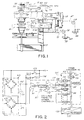
- a tire uniformity inspection machine 10 includes a frame 11 which supports mutually opposed upper and lower chucks 21 and 25, respectively, which co-operate to support a tire 14 to be tested.
- upper tire spindle 26 is fitted with a drive pulley 35 connected to a drive motor 36 by way of a timing belt 37.
- a rotary shaft encoder 40 is connected by chain 38 and sprocket 39 or a belt and pulley to rotate synchronously with upper tire spindle 26 and hence, tire 14.
- shaft encoder 40 produces a series of 128 nominally equally angularly spaced rotation pulses 42 on line 43.
- Each rotation pulse 42 specifies particular rotational position of tire 14 which can be identified according to its position with respect to a position reference pulse 45, one of which is generated by encoder 40 each revolution of tire 14.
- a cylindrical loadwheel 50 having a circumferential surface 51 is supported by loadwheel spindles 52 for free rotation about an axis parallel to that of the tire 14 under test.
- Loadwheel spindles 52 are in turn supported by a carriage 55 which is slidably secured to frame 11 by one or more ways 56 as to be moveable in the radial direction toward and away from tire 14 so that a desired average radial load can be imposed upon tire 14 to establish a standard test condition prior to the taking of measurement data.
- Carriage 55 is movable radially back and forth by a reversible D.C. motor 58 acting through a drive chain 59.
- the preferred apparatus and method for establishing a desired average radial load on tire 14 during testing thereof is more fully described in U.S. Patent No. 4,704,900.
- Loadwheel 50 is instrumented with a force transducer 63 which, in the preferred embodiment, comprises a pair of triaxial strain gauge loadcell assemblies, one of which, 63t, is mounted to the top end of loadwheel spindle 52 and the other one of which, 63b, is mounted to the bottom end of loadwheel spindle 52.
- Loadcell assemblies 63t and 63b are wired together as shown to generate a combined analog force signal which is correlated with the instantaneous force transmitted by the tire 14 under test to loadwheel 50 in the direction along which assemblies 63t and 63b respond.
- machine 10 is shown in Fig. 1 with a weight 65 mounted on a hanger fixture 66 and attached to the upper end of loadwheel spindle 52 by a cable 67 reaved around a pulley 68.
- a second weight 69 is mounted upon a second hanger fixture 70 and attached to the lower end of spindle 52 by way of a second cable 71 reaved around a second pulley 72.
- weights 65 and 69 exert a radially directed force on force transducer 63.
- weights 65 and 69 should be of equal mass and should have a combined total weight which need not exceed about one hundred pounds (50 kg) and preferably about fifty pounds (25 kg).
- a voltmeter 89 may be connected at the input of both the suppressed and unsuppressed channels across terminals 84 and 85 to read the magnitude, V, of the signal being applied to the channel.
- voltmeter 89 is a precision voltmeter having at least a forty millivolt range and a resolution of one microvolt or better and may suitably comprise a Model 8810A digital multimeter available from John Fluke Manufacturing Co. of Everett, Washington or equivalent.
- Channel input terminals 84 and 85 are connected to a signal processing network 87 having at its front end an instrumentation amplifier 91 which amplifies the signal appearing across terminals 84 and 85 by a gain which, in the case of a channel responsive to radial force variation in passenger car tires, is typically on the order of about two hundred (200).
- Amplifier 91 also electrically isolates transducer 63 from the remainder of the channel and applies any required offset.
- Amplifier 91 generates a single ended output signal 93 which is applied to the input of a filter 95 which serves to eliminate from signal 93 frequency components other than those of interest.
- the output of filter 95 comprises an unsuppressed analog signal 97 which, in the case of an unsuppressed channel, is applied to the input of an A/D converter 98 associated with that channel.
- unsuppressed signal 97 is applied to a suppression network connected ahead of A/D converter 100.
- the suppression network comprises a digital-to-analog (D/A) converter 110 which receives from a central processing unit (CPU) 115 a digital signal of a magnitude correlated to the magnitude of a D.C. component to be subtracted from signal 97 and generates a corresponding suppression signal 117 which summer 102 subtracts from unsuppressed signal 97 in order to generate a difference signal 104.
- Signal 104 is then applied to the input of amplifier 106 whose output represents a suppressed analog signal 120 which is in turn applied to the input of A/D converter 100.
- Amplifier 106 has a gain selected to scale signal 104 such that the expected range of signal 120 spans substantially the entire input range of A/D converter 100 thus providing improved measuring resolution.
- A/D converters 98 and 100 as well as D/A converter 110 in the preferred embodiment form part of a computer 125 which includes CPU 115.
- signals 42 and 45 communicate with CPU 115 through suitable I/O ports.
- Computer 125 is also connected by way of one or more suitable I/O ports to a display 130 such as a CRT as well as to a keyboard 131.
- the invention provides a novel apparatus and method for determining a calibration factor as well as tire testing method using same.
- One important aspect of the invention contemplates exciting each force measuring unsuppressed channel by applying thereto a so-called "first" signal whose magnitude, S1, is greater than the magnitude of any signal being generated by transducer 63 at the time the first signal is applied.
- the first signal is generated at least in part by means other than force transducer 63 and is preferably a D.C. signal applied at the input of signal processing network 87.
- the first signal should be stable and have a magnitude of the same order of magnitude as the largest signals usually generated by transducer when machine 10 is engaged in actual tire inspectinq operations.
- the first signal should have a magnitude in the range of about 50% to 100% and preferably about 75% of the full scale output of transducer 63 thus simulating the application of a large force (e.g., 2000 pounds or 1000 kg) to loadwheel 50.
- a large force e.g. 2000 pounds or 1000 kg
- a further aspect of the invention contemplates generating such a signal by connecting an impedance, arbitrarily designated here as Z1, between a source of electrical energy, such as power supply V+, and the input of signal processing network 87.
- an impedance arbitrarily designated here as Z1
- Z1 an impedance, arbitrarily designated here as Z1
- a source of electrical energy such as power supply V+
- signal processing network 87 This can be accomplished by connecting power supply V+ to terminal 84 by way of impedance Z1 and a series switch element 133 which remains open during tire inspecting operations but which can be closed for calibrating machine 10.
- This impedance is selected in relation to the energy level of the energy source such that the resulting first signal will be of the desired magnitude.
- impedance Z1 comprises a twenty-five (25) kilohm resistance provided by a resistor of a stable resistance type such as a commonly available type RN55D or equivalent.
- the invention further contemplates exciting the channel with a so-called "second" signal whose magnitude, S2, is greater than any signal being generated by transducer 63 at the time the second signal is being applied.
- This second signal which is also preferably a D.C. signal applied at the input of signal processing network 87, should be stable and be of a magnitude such as to cause the output of amplifier 106 to assume about 50% to 100% and preferably about 75% of its full scale output.
- the invention contemplates generating such a second siqnal by selectively connecting an impedance between an energy source, such as power supply V+, and the channel Such connection is preferably made at the input of signal processing network 87. That impedance is selected in relation to the energy level of the energy source such that the resulting second signal will be of the desired magnitude and may conveniently be formed as the equivalent impedance of impedance Z1 connected in parallel with a second impedance Z2. In the preferred embodiment, this is accomplished by connecting additional impedance Z2 in parallel with impedance Z1 between power supply V+ and terminal 84 through a switch element 134 as shown.
- impedance Z2 suitably comprises a 500 kilohm resistance provided by a resistor of a stable resistance type such as the aforementioned type RN55D. Since the parallel combination of impedances Z1 and Z2 represents a slightly lower equivalent impedance than Z1 alone, the second signal applied to the channel when Z1 and Z2 are both connected is of a magnitude, S2, which is slightly greater than the magnitude, S1, of the first signal. Thus, in the preferred embodiment, application of the second signal to the channel simulates the application of a slightly greater force to loadwheel 50 than that simulated by the first signal.
- Fig. 3 sets forth the basic steps for determining a calibration factor, C(u), of an unsuppressed channel of tire uniformity machine 10. It is assumed that switch elements 133 and 134 are both initially open. As indicated at step 144, voltmeter 89 is connected across terminals 84 and 85 at the input of signal processing network 87 to measure the voltage, V, appearing there. That value, arbitrarily designated here as Vinit, is recorded for use in subsequent calculations. Step 144 should be carried out while the force transducer 63 of machine 10 is under a substantially unloaded condition.
- step 144 may suitably be carried out with no external load whatsoever applied to transducer 63, it is preferably carried out while any fixtures, such as fixtures 66 and 70, as well as any cables, such as cables 67 and 71, which are necessary to apply weight to machine 10 in step 148 which will be described shortly are attached to machine 10.
- the digital output, A/D(u)out, of the A/D converter 98 associated with the unsuppressed channel is then read at step 146 and its value, arbitrarily designated here as Dinit, is recorded for use in subsequent calculations.
- a known total force such as that due to weight, W, is applied to transducer 63 so as to simulate the application of a corresponding force in the appropriate direction.
- weight W need not exceed about one hundred (100) pounds (50 kg) and is preferably about fifty (50) pounds (25 kg).
- a radial force measuring channel such a force may conveniently be applied by attaching weights 65 and 69 to machine 10 in the manner described earlier with reference to Fig. 1. With weight W so applied, the voltage, V, appearing across terminals 84 and 85, is measured at step 150 using voltmeter 89.
- the measured magnitude of that voltage represents the response of transducer 63 to the application of the actual force caused by weight W.
- Value Vw is recorded for use in subsequent calculations.
- weights 65 and 69 as well as fixtures 66 and 70 and cables 67 and 71 are then preferably, but optionally, detached from machine 10.
- G representing the magnitude of the transfer function associated with transducer 63 is calculated as the ratio of weight value W to the difference between values Vw and Vinit.
- impedance Z1 is connected in step 156 so as to excite the channel with the aforementioned first signal. This is done by connecting impedance Z1 between power supply V+ and the input of signal processing network 87 at terminal 84.
- step 156 is carried out simply by closing switch element 133.
- the magnitude, S1 of the first signal is measured with precision by again reading voltage V using voltmeter 89. Magnitude value S1 is then recorded for use in subsequent calculations.
- step 160 the apparent force or "weight”, arbitrarily designated here as Wz1, whose application was simulated by the application of the first siqnal is calculated as the product of transfer function value G and magnitude value S1.
- Wz1 represents the equivalent weight that would have to be applied to transducer 63 in order to generate a signal of the same magnitude as that applied by connecting impedance Z1.
- step 162 the magnitude of the digital signal A/D(u)out, then appearing at the output of the A/D converter 98 is read and recorded for use in subsequent calculations as a value arbitrarily designed here as D(u).
- step 164 the calibration factor for the unsuppressed channel, arbitrarily designated here as C(u), is calculated as the ratio of value Wz1 to the difference between values D(u) and D(u)init.
- the calibration factor value, C(u), so determined is then entered via keyboard 131 and retrievably stored in memory within computer 125 so as to be selectively available for solving an equation of the form of Equation 1 in the course of determining the value of at least one non-uniformity-indicating parameter characterizing a tire 14 when machine 10 is in use.
- value Wz1 will reflect the sum of the actual force applied by weight w as well as the apparent force simulated by the connection of impedance Z1.
- the value of first signal S1 measured in step 158 will also include a component generated by force transducer 63 corresponding to the actual applied weight W. Even so, the ultimately determined calibration factor value, C(u), will be the same whether optional step 152 is carried out or not.
- step 184 preferably comprises carrying out steps 144, 148, 150, 152 and 154 as described above with reference to Fig. 3 although step 152 remains optional.
- a suppression signal 117 of a magnitude which is preferably sufficient to substantially null the first signal is applied to one input of summer 102.
- switch element 133 is closed so as to apply the first signal to the channel.
- CPU 155 then executes an instruction to read the magnitude value of the digital output signal, A/D(s)out, generated by A/D converter 100 in response to the first signal and to apply a digital signal of that same magnitude to the input of D/A converter 110.
- D/A converter 110 then generates suppression signal 117 so as to be of a corresponding magnitude and applies suppression signal 117 to summer 102.
- switch element 133 is opened so as to remove the first signal prior to the execution of step 188.
- a so-called "second" signal of a magnitude, S2 is then applied to excite the channel in step 190.
- this second signal is preferably applied at terminals 84 and 85 which define the input to the channel via signal processing network 87.
- the second signal can be applied in any suitable manner, such as by connecting a signal generator across terminals 84 and 85, a further aspect of the invention contemplates that the second signal be generated by connecting an impedance between power supply V+ and terminal 84. In the preferred embodiment, this is accomplished simply by closing both switch elements 133 and 134 so that the last mentioned impedance is defined by the parallel combination of impedances Z1 and Z2.
- the magnitude, S2 of the second signal generated thereby is measured with precision at step 192 by once more reading the voltage, V, across terminals 84 and 85 using voltmeter 89. Magnitude value S2 is then recorded for use in subsequent calculations.
- a value arbitrarily designated here as Wz2 representing the weight whose application is simulated by the application of the second signal to the channel is calculated as the product of S2 and transfer function value G.
- step 196 with Z1 and Z2 both remaining connected by virtue of the continued closure of switch elements 133 and 134, a value arbitrarily designated here as D(s) representing the magnitude of the digital signal, A/D(s)out, generated by A/D converter 100 is read and recorded for use in subsequent calculations.
- the calibration factor for the suppressed channel arbitrarily designated here as C(s) is calculated as the ratio of value Wz2 to the difference between values D(s) and D(s)init.
- the calibration factor for the suppressed channel is retrievably stored in computer 125 so as to be selectively available for use in computing the value of a non-uniformity-indicating parameter. This may be conveniently accomplished by entering value C(s) into the memory of computer 125 via keyboard 131.
- value Wz2 will reflect the sum of the actual force applied by weight W as well as the apparent force simulated by the parallel equivalent impedance presented by the connection of impedances Z1 and Z2.
- the value of the second signal S2 in such case will also include a component corresponding to actual weight W.
- the value of the calibration factor, C(s) will be the same whether optional step 152 is carried out or not.
- any weights and/or fixtures still applied to machine 10 for calibration purposes are removed and switch elements 133 and 134 are both opened. Machine 10 is then ready to commence testing tires.
- drive motor 36 causes tire 14 mounted on chucks 21 and 25 to rotate at a nominally constant test speed of 60 RPM.
- Carriage 55 is then driven radially inward toward tire 14 and the averaqe radial load on the tire is established at a desired value in the manner described in the above referenced U. S. Patent No. 4,704,900.
- the magnitude of the average radial load so applied corresponds to the magnitude of suppression signal 117 to be applied to summer 102 while tire 14 is being tested.
- shaft encoder 40 generates one hundred twenty-eight (128) nominally equally angularly spaced rotation pulses 42 and a single reference pulse 45. Since the rotation of encoder 40 is synched to the rotation of tire 14, the rising edge of each rotation pulse 42 represents a particular angular location on tire 14.
- CPU 115 and the A/D converters 100 and 98 co-operate to digitally sample the suppressed analog signal 120 an the unsuppressed analog signal 97 appearing at their respective inputs.
- the A/D converters associated with each additional suppressed or unsuppressed channel also sample the signals appearing at their inputs in a similar manner at the rising edge of each rotation pulse 42.
- a data field consisting of a plurality of such data samples is stored by computer 125. From each such data field, the value of a particular non-uniformity-indicating parameter is then calculated by CPU 115.
- the inventions described and claimed in earlier issued, U.S. Patent No. 4,805,125, are employed where applicable in order to provide best measurement accuracy.
- each non-uniformity-indicating parameter so determined may be displayed on display 130, retrievably stored in memory and/or compared with specification criteria in order to grade the non-uniformity of the tire and/or in order to initiate further action such as rejecting the tire if the specification criteria are not met. In appropriate cases, such comparison may also be used to initiate appropriate corrective measures such as grinding the tire in selected areas in order to improve its performance.
- Machine 10 should be calibrated before commencing initial operation and again from time-to-time as often as necessary to maintain accuracy notwithstanding drift in component specifications, ambient changes and the like.
Landscapes
- Physics & Mathematics (AREA)
- General Physics & Mathematics (AREA)
- Testing Of Balance (AREA)
- Tires In General (AREA)
Applications Claiming Priority (2)
| Application Number | Priority Date | Filing Date | Title |
|---|---|---|---|
| US07/788,086 US5309377A (en) | 1991-11-05 | 1991-11-05 | Calibration apparatus and method for improving the accuracy of tire uniformity measurements and tire testing method using same |
| US788086 | 1991-11-05 |
Publications (2)
| Publication Number | Publication Date |
|---|---|
| EP0541354A2 true EP0541354A2 (de) | 1993-05-12 |
| EP0541354A3 EP0541354A3 (en) | 1993-06-09 |
Family
ID=25143411
Family Applications (1)
| Application Number | Title | Priority Date | Filing Date |
|---|---|---|---|
| EP19920310105 Withdrawn EP0541354A3 (en) | 1991-11-05 | 1992-11-04 | Calibration apparatus and method for a tire testing machine |
Country Status (3)
| Country | Link |
|---|---|
| US (1) | US5309377A (de) |
| EP (1) | EP0541354A3 (de) |
| JP (1) | JPH07198549A (de) |
Cited By (1)
| Publication number | Priority date | Publication date | Assignee | Title |
|---|---|---|---|---|
| DE4329830A1 (de) * | 1993-09-03 | 1995-03-09 | Hofmann Maschinenbau Gmbh | Verfahren und Vorrichtung zur Prüfung einer Kraftmeßeinrichtung einer Reifengleichförmigkeitsmeßmaschine |
Families Citing this family (19)
| Publication number | Priority date | Publication date | Assignee | Title |
|---|---|---|---|---|
| DE4430462A1 (de) * | 1994-08-27 | 1996-02-29 | Teves Gmbh Alfred | Verfahren zum schnellen Erkennen eines Notrades |
| US5614676A (en) * | 1996-03-08 | 1997-03-25 | The Goodyear Tire & Rubber Company | Method of machine vibration analysis for tire uniformity machine |
| US6415197B1 (en) | 1997-10-08 | 2002-07-02 | The Goodyear Tire & Rubber Company | Method of displaying characteristic parameters in a tire manufacturing cell |
| GB2340951B (en) * | 1998-08-20 | 2000-07-12 | Gec Avery Ltd | Weight simulation calibration rig and method |
| US6257956B1 (en) | 2000-03-06 | 2001-07-10 | The Goodyear Tire & Rubber Company | Method to identify and remove machine contributions from tire uniformity measurements |
| KR100394251B1 (ko) * | 2001-05-28 | 2003-08-09 | 진을천 | 타이어 휠의 언밸런스 측정장치 및 그 방법 |
| JP4339048B2 (ja) * | 2003-08-25 | 2009-10-07 | 国際計測器株式会社 | タイヤのユニフォーミティ計測方法及び装置、並びにタイヤ修正方法及び装置 |
| DE102006038733A1 (de) * | 2006-08-19 | 2008-02-21 | inmess Gesellschaft für Industrie- und Meßtechnik mbH | Gleichförmigkeits-Messmaschine für Fahrzeugreifen |
| US20110133755A1 (en) | 2009-12-08 | 2011-06-09 | Delphi Technologies, Inc. | System and Method of Occupant Detection with a Resonant Frequency |
| JP5450475B2 (ja) * | 2011-02-10 | 2014-03-26 | 三菱重工マシナリーテクノロジー株式会社 | 校正装置 |
| US8701479B2 (en) | 2012-02-10 | 2014-04-22 | Commercial Time Sharing Inc. | System for characterizing tire uniformity machines and methods of using the characterizations |
| US9140628B2 (en) | 2012-02-10 | 2015-09-22 | Akron Special Machinery, Inc. | System for characterizing tire uniformity machines and methods of using the characterizations |
| US8943881B2 (en) | 2012-02-10 | 2015-02-03 | Akron Special Machinery, Inc. | System for characterizing tire uniformity machines and methods of using the characterizations |
| KR101440338B1 (ko) * | 2012-11-27 | 2014-09-15 | 한국타이어 주식회사 | 4개의 힘센서를 이용한 코니시티 측정 시스템 및 방법 |
| JP5940041B2 (ja) * | 2013-11-07 | 2016-06-29 | 株式会社神戸製鋼所 | タイヤ試験機の校正装置及びタイヤ試験機の校正方法 |
| US9677972B2 (en) | 2015-10-26 | 2017-06-13 | Commercial Time Sharing Inc. | System and method for characterizing tire uniformity machines |
| CN105241606B (zh) * | 2015-11-26 | 2018-02-02 | 重庆理工大学 | 一种选换挡力传感器标定方法 |
| JP6770409B2 (ja) * | 2016-11-21 | 2020-10-14 | 三菱重工業株式会社 | 押付力測定方法 |
| CN110612438B (zh) | 2017-02-22 | 2022-03-22 | 三菱重工机械系统株式会社 | 旋转体载荷测量装置 |
Family Cites Families (12)
| Publication number | Priority date | Publication date | Assignee | Title |
|---|---|---|---|---|
| US3656343A (en) * | 1970-02-02 | 1972-04-18 | Goodyear Tire & Rubber | Apparatus for processing cured tires |
| US3899917A (en) * | 1973-12-06 | 1975-08-19 | Frederick N Kisbany | Laboratory wear resistance test machine for tires |
| US4067060A (en) * | 1976-07-06 | 1978-01-03 | Canadian Patents And Development Limited | Transfer function measurement |
| FR2475214A1 (fr) * | 1980-02-01 | 1981-08-07 | Sedeme | Dispositif d'etalonnage pour chaine de mesure d'extensometrie, procede d'etalonnage, et appareil de mesure mettant en oeuvre un tel dispositif |
| GB2089540B (en) * | 1980-06-19 | 1984-07-18 | Rolls Royce | Strain gauge simulator |
| US4404848A (en) * | 1981-02-26 | 1983-09-20 | Kabushiki Kaisha Kobe Seiko Sho | Method for correcting measurement errors in tire uniformity inspecting machines |
| GB2108674A (en) * | 1981-10-31 | 1983-05-18 | Rolls Royce | Transducer simulator |
| US4800749A (en) * | 1986-08-15 | 1989-01-31 | Hewlett-Packard Company | Transducer calibration circuit |
| US4704900A (en) * | 1986-08-19 | 1987-11-10 | Eagle-Picher Industries, Inc. | Apparatus and method for imposing a desired average radial force on a tire |
| KR960000995B1 (ko) * | 1987-06-12 | 1996-01-15 | 이글 피쳐 인더스트리즈 인코포레이티드 | 물체 균일 측정 장치 및 방법 |
| SU1583753A1 (ru) * | 1988-05-31 | 1990-08-07 | Предприятие П/Я А-3759 | Устройство дл калибровки многоканальной аппаратуры |
| DE3835985A1 (de) * | 1988-10-21 | 1990-04-26 | Hofmann Gmbh & Co Kg Maschinen | Verfahren und vorrichtung zur bestimmung der gleichfoermigkeit von luftreifen, insbesondere kraftfahrzeugreifen |
-
1991
- 1991-11-05 US US07/788,086 patent/US5309377A/en not_active Expired - Lifetime
-
1992
- 1992-11-04 EP EP19920310105 patent/EP0541354A3/en not_active Withdrawn
- 1992-11-05 JP JP4319220A patent/JPH07198549A/ja active Pending
Cited By (2)
| Publication number | Priority date | Publication date | Assignee | Title |
|---|---|---|---|---|
| DE4329830A1 (de) * | 1993-09-03 | 1995-03-09 | Hofmann Maschinenbau Gmbh | Verfahren und Vorrichtung zur Prüfung einer Kraftmeßeinrichtung einer Reifengleichförmigkeitsmeßmaschine |
| DE4329830C2 (de) * | 1993-09-03 | 2002-10-31 | Hofmann Maschinen Und Anlagenbau Gmbh | Verfahren und Vorrichtung zur Prüfung einer Kraftmeßeinrichtung einer Reifengleichförmigkeitsmeßmaschine |
Also Published As
| Publication number | Publication date |
|---|---|
| JPH07198549A (ja) | 1995-08-01 |
| EP0541354A3 (en) | 1993-06-09 |
| US5309377A (en) | 1994-05-03 |
Similar Documents
| Publication | Publication Date | Title |
|---|---|---|
| US5309377A (en) | Calibration apparatus and method for improving the accuracy of tire uniformity measurements and tire testing method using same | |
| US3847017A (en) | Strain measuring system | |
| JPS6058525A (ja) | 2つの面で車輪のつりあい機を較正する装置と方法 | |
| JP2000074986A (ja) | デバイス試験装置 | |
| AU3646284A (en) | Non-destructive eddy-current testing | |
| CN104697712B (zh) | 一种回转体工件质心检验方法 | |
| US6223138B1 (en) | Carrier frequency measuring method and apparatus | |
| CN106052956A (zh) | 一种力锤灵敏度自动校准装置及其校准方法 | |
| JPH0124249B2 (de) | ||
| JPH0222327B2 (de) | ||
| US4545239A (en) | Method and apparatus for controlling the quality of tires | |
| GB2026168A (en) | Determining tensile yield point | |
| SU735942A1 (ru) | Способ поверки силоизмерительных преобразователей и устройство дл его реализации | |
| Levi | Drill press dynamometers | |
| CN1034996A (zh) | 夹持式钢索张力测定器及标定台 | |
| SU1670440A1 (ru) | Способ групповой градуировки датчиков силы сжати | |
| JP2000019089A (ja) | 硬さ試験機用校正装置の校正方法 | |
| Money et al. | Calibration of quartz load cells; An in-situ procedure for instrumented falling weight impact machines | |
| JPH0396872A (ja) | コイル試験方法とその方法に用いる装置 | |
| RU1793200C (ru) | Многоканальный тензопреобразователь | |
| CN117968933A (zh) | 一种基于三点弯曲法钢丝绳张力测试仪的校准方法 | |
| SU1089440A1 (ru) | Способ градуировки силоизмерительных преобразователей | |
| Hiti | Validation of combinatorial evaluation of strain-gauge amplifier linearity | |
| SU645043A1 (ru) | Установка дл поверки динамометров | |
| CN119437629A (zh) | 一种旋翼应变天平动态性能标定方法 |
Legal Events
| Date | Code | Title | Description |
|---|---|---|---|
| PUAI | Public reference made under article 153(3) epc to a published international application that has entered the european phase |
Free format text: ORIGINAL CODE: 0009012 |
|
| PUAL | Search report despatched |
Free format text: ORIGINAL CODE: 0009013 |
|
| AK | Designated contracting states |
Kind code of ref document: A2 Designated state(s): DE FR GB IT LU |
|
| AK | Designated contracting states |
Kind code of ref document: A3 Designated state(s): DE FR GB IT LU |
|
| 17P | Request for examination filed |
Effective date: 19931207 |
|
| 18W | Application withdrawn |
Withdrawal date: 19950130 |