EP0540977B1 - Moteur à combustion interne avec pompe à huile sur l'arbre à cames - Google Patents
Moteur à combustion interne avec pompe à huile sur l'arbre à cames Download PDFInfo
- Publication number
- EP0540977B1 EP0540977B1 EP92118294A EP92118294A EP0540977B1 EP 0540977 B1 EP0540977 B1 EP 0540977B1 EP 92118294 A EP92118294 A EP 92118294A EP 92118294 A EP92118294 A EP 92118294A EP 0540977 B1 EP0540977 B1 EP 0540977B1
- Authority
- EP
- European Patent Office
- Prior art keywords
- pump
- combustion engine
- internal combustion
- camshaft
- engine according
- Prior art date
- Legal status (The legal status is an assumption and is not a legal conclusion. Google has not performed a legal analysis and makes no representation as to the accuracy of the status listed.)
- Expired - Lifetime
Links
- 238000002485 combustion reaction Methods 0.000 title claims description 8
- 238000007789 sealing Methods 0.000 claims description 3
- 238000012423 maintenance Methods 0.000 description 4
- 238000009825 accumulation Methods 0.000 description 1
- 230000009916 joint effect Effects 0.000 description 1
- 238000003754 machining Methods 0.000 description 1
- 238000004519 manufacturing process Methods 0.000 description 1
- 210000000056 organ Anatomy 0.000 description 1
- 230000000737 periodic effect Effects 0.000 description 1
Images


Classifications
-
- F—MECHANICAL ENGINEERING; LIGHTING; HEATING; WEAPONS; BLASTING
- F01—MACHINES OR ENGINES IN GENERAL; ENGINE PLANTS IN GENERAL; STEAM ENGINES
- F01M—LUBRICATING OF MACHINES OR ENGINES IN GENERAL; LUBRICATING INTERNAL COMBUSTION ENGINES; CRANKCASE VENTILATING
- F01M1/00—Pressure lubrication
- F01M1/06—Lubricating systems characterised by the provision therein of crankshafts or connecting rods with lubricant passageways, e.g. bores
-
- F—MECHANICAL ENGINEERING; LIGHTING; HEATING; WEAPONS; BLASTING
- F01—MACHINES OR ENGINES IN GENERAL; ENGINE PLANTS IN GENERAL; STEAM ENGINES
- F01M—LUBRICATING OF MACHINES OR ENGINES IN GENERAL; LUBRICATING INTERNAL COMBUSTION ENGINES; CRANKCASE VENTILATING
- F01M1/00—Pressure lubrication
- F01M1/02—Pressure lubrication using lubricating pumps
Definitions
- the present invention relates to an internal combustion engine, the particular arrangement of the pressure pump of the type with tangential pinion gears, for the circulation of oil in the various organs, makes it possible to reduce the bulk and the weight. said motor, as well as its maintenance cost, for example during disassembly.
- the pressure pump used to circulate the oil in the various greasing members is constituted by an autonomous mechanical assembly with closed casing, driven either directly by the crankshaft, or indirectly by the latter, by appropriate means. , such as gears or a toothed belt.
- the engine according to the invention has, on the contrary, a pressure pump for the circulation of oil with a sump open on one side, closed by direct fixing on the cylinder head, the movable members of the pump being directly driven by the camshaft, to which they are secured by means of an axial stop.
- the seal between the cylinder head and the pump body is ensured by O-rings and lip seals, and the axial play is adjusted by means of a flat washer, disposed between an annular shoulder of the body. pump and the corresponding internal face of the movable member of the pump driven by the camshaft.
- FIG. 1 it appears that the pump 1, partially masked by the drive wheel 2 of the camshaft, is fixed by the screws 3 on the cylinder head 5 of the engine. Also shown in this figure are the inlet 6 and outlet 7 ducts for the pump oil as well as the inlet duct 8 for the oil in the distribution member 22 on the bearings of the shaft to cams.
- the pulley 11 constitutes only a tensor for the belt coming from the pulley 9 fixed on the crankshaft.
- Figure 2 which shows an enlarged view of the section along line II-II of Figure 1, shows the assembly of the camshaft 20, located in the cylinder head 5 with, on the one hand the oil distribution 22 on the bearings, and on the other hand the pump 1 and the flywheel 2.
- the body of the pump 1 appears in dotted lines one of the fixing screws 24 of the pump body on the cylinder head.
- the O-ring 25 seals between the pump body and the cylinder head, and the seal 26 between the pump body and the open end of the oil distribution member 22 on the shaft bearings with cams.
- the washer 28 and the screw 29 constitute the stop for the camshaft, the latter being made integral with the drive wheel 2 in rotation by the key 30.
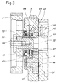
- FIG. 3 which is an enlargement of a part of FIG. 2, makes it possible to better understand the embodiment of the invention at the level of the pump itself.
- the reference 40 designates the drive pinion of the gear pump and the reference 41 designates the idler gear.
- the part 43 is a collar ring, engaged on the camshaft 20, between the flywheel 2 and the pinion 40, the lip seal 45 bearing on said collar ring.
- the pinion 40 is itself supported on the annular shoulder 50 of the camshaft.
- the planar washer 47 is positioned between the internal face of the drive pinion 40 and a shoulder 49 of the pump block. In this shoulder also appears in dotted lines a breather 51 connecting the space where the seal 45 is located and the suction side of the pump.
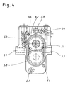
- Figure 4 shows the inlet ports 53 and outlet 54 of the oil; the holes 56 are intended for the guide pins and the holes 24 for the assembly screws 3; the grooves 58 and 59 are intended to receive the seals between the body of the pump 1 and, on the one hand the cylinder head 5, on the other hand the oil distribution member 22 on the bearings of the camshaft.
- Reference 60 designates the safety valve assembly.
- the return duct 62 of the safety valve also appears in section in FIGS. 2 and 3.
- the seal between the pump body and the cylinder head is ensured by the O-ring 25, housed in the groove 58, and kept in pressure by means of the screws 3. It therefore appears, once the drive wheel 2 removed, that the simple unscrewing of the screws 3 allows both to remove and disassemble the pump for its maintenance.
- the O-ring 26, housed in the groove 59 makes it possible to hermetically seal the orifice of the duct of the oil distribution member 22, said orifice resulting from the imperatives of machining.
Landscapes
- Engineering & Computer Science (AREA)
- Mechanical Engineering (AREA)
- General Engineering & Computer Science (AREA)
- Lubrication Of Internal Combustion Engines (AREA)
- Valve-Gear Or Valve Arrangements (AREA)
- Rotary Pumps (AREA)
- Lubrication Details And Ventilation Of Internal Combustion Engines (AREA)
- Cylinder Crankcases Of Internal Combustion Engines (AREA)
Applications Claiming Priority (2)
| Application Number | Priority Date | Filing Date | Title |
|---|---|---|---|
| FR9113769A FR2683262B1 (fr) | 1991-11-06 | 1991-11-06 | Moteur a combustion interne avec pompe a huile sur l'arbre a cames. |
| FR9113769 | 1991-11-06 |
Publications (2)
| Publication Number | Publication Date |
|---|---|
| EP0540977A1 EP0540977A1 (fr) | 1993-05-12 |
| EP0540977B1 true EP0540977B1 (fr) | 1995-09-13 |
Family
ID=9418733
Family Applications (1)
| Application Number | Title | Priority Date | Filing Date |
|---|---|---|---|
| EP92118294A Expired - Lifetime EP0540977B1 (fr) | 1991-11-06 | 1992-10-26 | Moteur à combustion interne avec pompe à huile sur l'arbre à cames |
Country Status (21)
| Country | Link |
|---|---|
| US (1) | US5295463A (cs) |
| EP (1) | EP0540977B1 (cs) |
| JP (1) | JP3316006B2 (cs) |
| KR (1) | KR100296020B1 (cs) |
| CN (1) | CN1040036C (cs) |
| AR (1) | AR248177A1 (cs) |
| AT (1) | ATE127880T1 (cs) |
| AU (1) | AU655387B2 (cs) |
| BR (1) | BR9204239A (cs) |
| CA (1) | CA2082207C (cs) |
| CZ (1) | CZ329192A3 (cs) |
| DE (1) | DE69204798T2 (cs) |
| ES (1) | ES2081026T3 (cs) |
| FR (1) | FR2683262B1 (cs) |
| HU (1) | HU217855B (cs) |
| IL (1) | IL103423A (cs) |
| PL (1) | PL169445B1 (cs) |
| RU (1) | RU2055220C1 (cs) |
| SK (1) | SK329192A3 (cs) |
| TW (1) | TW203112B (cs) |
| ZA (1) | ZA927879B (cs) |
Families Citing this family (15)
| Publication number | Priority date | Publication date | Assignee | Title |
|---|---|---|---|---|
| DE4424248C1 (de) * | 1994-07-09 | 1995-12-07 | Porsche Ag | Brennkraftmaschine mit zwei gegen die Vertikale geneigten Zylinderbänken |
| DE19624240C5 (de) * | 1996-06-18 | 2011-07-28 | Daimler AG, 70327 | Brennkraftmaschine |
| WO1999036686A1 (en) * | 1998-01-15 | 1999-07-22 | Stanadyne Automotive Corp. | Hydraulic pump with engine mounted drive bearing |
| EP0971116B1 (en) * | 1998-05-11 | 2003-12-03 | Yamaha Hatsudoki Kabushiki Kaisha | Internal combustion engine |
| US6047667A (en) * | 1998-07-24 | 2000-04-11 | Harley-Davidson Motor Company | Motorcycle camshaft support plate |
| US7174998B2 (en) * | 2001-10-15 | 2007-02-13 | Borgwarner Inc. | Submerged electric fluid pump |
| US7219645B2 (en) * | 2005-07-01 | 2007-05-22 | Harley-Davidson Motor Company Group, Inc. | Oil pump for a motorcycle |
| USD544509S1 (en) | 2005-09-30 | 2007-06-12 | S&S Cycle, Inc. | Gear cover |
| US7171939B1 (en) | 2005-09-30 | 2007-02-06 | S&S Cycle, Inc. | Integrated cam drive and oil pump assembly for motorcycle engines and the like |
| DE102007012704A1 (de) * | 2007-03-16 | 2008-09-18 | Robert Bosch Gmbh | Hochdruckpumpe zur Förderung von Kraftstoff mit einer verbesserten Ausbildung der Lageranordnung zur Lagerung der Nockenwelle |
| JP4247644B2 (ja) * | 2007-06-29 | 2009-04-02 | 三菱自動車工業株式会社 | 内燃機関の可変動弁装置 |
| DE102008007285A1 (de) * | 2008-02-02 | 2009-08-06 | Bayerische Motoren Werke Aktiengesellschaft | Nockenwellengetriebene Pumpe für eine Kraftfahrzeug-Brennkraftmaschine und Kraftfahrzeug-Brennkraftmaschine |
| DE102009016048B4 (de) * | 2009-04-02 | 2018-05-30 | Bayerische Motoren Werke Aktiengesellschaft | Pumpe für eine Kraftfahrzeug-Brennkraftmaschine sowie Kraftfahrzeug-Brennkraftmaschine mit Pumpe |
| JP2010285884A (ja) * | 2009-06-09 | 2010-12-24 | Fuji Heavy Ind Ltd | エンジンの潤滑装置 |
| RU2539233C2 (ru) * | 2013-01-10 | 2015-01-20 | Открытое акционерное общество "Автодизель" (Ярославский моторный завод) | Двигатель внутреннего сгорания |
Citations (1)
| Publication number | Priority date | Publication date | Assignee | Title |
|---|---|---|---|---|
| EP0517014A1 (de) * | 1991-06-07 | 1992-12-09 | Schwäbische Hüttenwerke Gesellschaft mit beschränkter Haftung | Zahnradpumpe für Öl für einen Verbrennungsmotor, insbesondere für Kraftfahrzeuge |
Family Cites Families (8)
| Publication number | Priority date | Publication date | Assignee | Title |
|---|---|---|---|---|
| US3087582A (en) * | 1961-07-10 | 1963-04-30 | American Motors Corp | Engine lubricating apparatus |
| GB1365805A (en) * | 1972-02-11 | 1974-09-04 | Cunewalde Motoren | Internal combustion engines |
| US4573439A (en) * | 1979-12-18 | 1986-03-04 | Cummins Engine Company, Inc. | Oil pump arrangement for supplying oil under pressure in an internal combustion engine |
| DE3044253A1 (de) * | 1980-11-25 | 1982-06-24 | Bayerische Motoren Werke AG, 8000 München | Brennkraftmaschine, insbesondere einreihige mehrzylinder-brennkraftmaschine |
| FR2540553A1 (fr) * | 1983-02-03 | 1984-08-10 | Renault | Dispositif de commande a came, notamment pour soupapes de moteurs a combustion interne |
| AT389739B (de) * | 1984-09-21 | 1990-01-25 | Avl Verbrennungskraft Messtech | Viertakt-brennkraftmaschine mit einer als zahnradpumpe ausgebildeten schmieroelpumpe |
| IT1180140B (it) * | 1984-11-19 | 1987-09-23 | Tecnamotor Spa | Albero di distribuzione composito per motori endotermici |
| FR2607867B1 (fr) * | 1986-12-08 | 1991-01-11 | Peugeot | Dispositif assurant la circulation d'un lubrifiant dans un circuit de lubrification d'un moteur a combustion interne |
-
1991
- 1991-11-06 FR FR9113769A patent/FR2683262B1/fr not_active Expired - Fee Related
-
1992
- 1992-10-13 ZA ZA927879A patent/ZA927879B/xx unknown
- 1992-10-14 IL IL10342392A patent/IL103423A/en not_active IP Right Cessation
- 1992-10-26 DE DE69204798T patent/DE69204798T2/de not_active Expired - Fee Related
- 1992-10-26 AT AT92118294T patent/ATE127880T1/de not_active IP Right Cessation
- 1992-10-26 ES ES92118294T patent/ES2081026T3/es not_active Expired - Lifetime
- 1992-10-26 EP EP92118294A patent/EP0540977B1/fr not_active Expired - Lifetime
- 1992-10-27 HU HU9203373A patent/HU217855B/hu not_active IP Right Cessation
- 1992-10-27 KR KR1019920019781A patent/KR100296020B1/ko not_active Expired - Fee Related
- 1992-10-29 JP JP29133592A patent/JP3316006B2/ja not_active Expired - Fee Related
- 1992-10-30 BR BR929204239A patent/BR9204239A/pt not_active IP Right Cessation
- 1992-11-02 SK SK3291-92A patent/SK329192A3/sk unknown
- 1992-11-02 CZ CS923291A patent/CZ329192A3/cs unknown
- 1992-11-04 PL PL92296470A patent/PL169445B1/pl unknown
- 1992-11-05 AU AU28159/92A patent/AU655387B2/en not_active Ceased
- 1992-11-05 RU RU9292004383A patent/RU2055220C1/ru active
- 1992-11-05 CN CN92112895A patent/CN1040036C/zh not_active Expired - Fee Related
- 1992-11-05 AR AR92323594A patent/AR248177A1/es active
- 1992-11-05 CA CA002082207A patent/CA2082207C/en not_active Expired - Fee Related
- 1992-11-06 US US07/973,817 patent/US5295463A/en not_active Expired - Fee Related
- 1992-11-10 TW TW081109061A patent/TW203112B/zh active
Patent Citations (1)
| Publication number | Priority date | Publication date | Assignee | Title |
|---|---|---|---|---|
| EP0517014A1 (de) * | 1991-06-07 | 1992-12-09 | Schwäbische Hüttenwerke Gesellschaft mit beschränkter Haftung | Zahnradpumpe für Öl für einen Verbrennungsmotor, insbesondere für Kraftfahrzeuge |
Also Published As
| Publication number | Publication date |
|---|---|
| IL103423A0 (en) | 1993-03-15 |
| CA2082207A1 (en) | 1993-05-07 |
| US5295463A (en) | 1994-03-22 |
| HU9203373D0 (en) | 1993-03-01 |
| KR100296020B1 (ko) | 2001-11-22 |
| DE69204798D1 (de) | 1995-10-19 |
| AR248177A1 (es) | 1995-06-30 |
| AU2815992A (en) | 1993-05-13 |
| BR9204239A (pt) | 1993-05-11 |
| HU217855B (hu) | 2000-04-28 |
| JP3316006B2 (ja) | 2002-08-19 |
| AU655387B2 (en) | 1994-12-15 |
| RU2055220C1 (ru) | 1996-02-27 |
| IL103423A (en) | 1995-07-31 |
| CN1040036C (zh) | 1998-09-30 |
| HUT63484A (en) | 1993-08-30 |
| FR2683262A1 (fr) | 1993-05-07 |
| PL296470A1 (en) | 1993-07-12 |
| CZ329192A3 (en) | 1993-05-12 |
| EP0540977A1 (fr) | 1993-05-12 |
| TW203112B (cs) | 1993-04-01 |
| KR930010352A (ko) | 1993-06-22 |
| FR2683262B1 (fr) | 1995-02-03 |
| ZA927879B (en) | 1993-04-21 |
| CN1075773A (zh) | 1993-09-01 |
| PL169445B1 (pl) | 1996-07-31 |
| SK329192A3 (en) | 1995-05-10 |
| JPH05214916A (ja) | 1993-08-24 |
| CA2082207C (en) | 2002-09-17 |
| ES2081026T3 (es) | 1996-02-16 |
| DE69204798T2 (de) | 1996-05-02 |
| ATE127880T1 (de) | 1995-09-15 |
Similar Documents
| Publication | Publication Date | Title |
|---|---|---|
| EP0540977B1 (fr) | Moteur à combustion interne avec pompe à huile sur l'arbre à cames | |
| JPS6052285B2 (ja) | 内燃機関用油ポンプ及び駆動装置組立体 | |
| FR3022300A1 (fr) | Dispositif de lubrification pour une turbomachine | |
| CN209557101U (zh) | 可变压缩比机构 | |
| EP4023909B1 (fr) | Porte-satellites pour un reducteur mecanique de turbomachine d aeronef | |
| FR2556775A1 (fr) | Dispositif de limitation de la pression dans un circuit de lubrification de moteur | |
| EP0271384B1 (fr) | Dispositif assurant la circulation d'un lubrifiant dans un circuit de lubrification d'un moteur à combustion interne | |
| CN111577604A (zh) | 一种串联泵 | |
| FR2491171A3 (fr) | Dispositif tournant de pompage capable de supporter un element tournant tout en debitant un liquide ayant des proprietes lubrifiantes | |
| CN100389284C (zh) | 一种内燃机机油泵 | |
| FR2509802A1 (fr) | Pompes et moteurs | |
| FR2657920A1 (fr) | Moteur a combustion interne a piston rotatif. | |
| JP2004225702A (ja) | オイルモジュール | |
| FR2482208A1 (cs) | ||
| JPS6221687Y2 (cs) | ||
| FR2478221A1 (fr) | Machine a engrenage, telle que pompe ou moteur hydraulique | |
| FR2500889A1 (fr) | Pompe a palettes | |
| JPS61135993A (ja) | 回転式歯車ポンプ | |
| FR2657919A1 (fr) | Moteur a combustion interne a piston rotatif. | |
| KR19990007248A (ko) | 유압 펌프 | |
| EP1567751A1 (fr) | Dispositif d'accouplement d'un organe rotatif a un arbre a cames | |
| JPH11294691A (ja) | ポンプ装置 | |
| KR100610072B1 (ko) | 자동변속기의 오일펌프 | |
| EP0597743B1 (fr) | Agencement d'une pompe à huile de lubrification d'un moteur à combustion | |
| JP2508022B2 (ja) | 点火配電器のオイルシ−ルの潤滑機構 |
Legal Events
| Date | Code | Title | Description |
|---|---|---|---|
| PUAI | Public reference made under article 153(3) epc to a published international application that has entered the european phase |
Free format text: ORIGINAL CODE: 0009012 |
|
| AK | Designated contracting states |
Kind code of ref document: A1 Designated state(s): AT BE CH DE DK ES GB GR IE IT LI LU NL PT SE |
|
| 17P | Request for examination filed |
Effective date: 19930614 |
|
| 17Q | First examination report despatched |
Effective date: 19940712 |
|
| GRAA | (expected) grant |
Free format text: ORIGINAL CODE: 0009210 |
|
| AK | Designated contracting states |
Kind code of ref document: B1 Designated state(s): AT BE CH DE DK ES GB GR IE IT LI LU NL PT SE |
|
| PG25 | Lapsed in a contracting state [announced via postgrant information from national office to epo] |
Ref country code: DK Effective date: 19950913 Ref country code: GR Free format text: LAPSE BECAUSE OF FAILURE TO SUBMIT A TRANSLATION OF THE DESCRIPTION OR TO PAY THE FEE WITHIN THE PRESCRIBED TIME-LIMIT Effective date: 19950913 |
|
| REF | Corresponds to: |
Ref document number: 127880 Country of ref document: AT Date of ref document: 19950915 Kind code of ref document: T |
|
| REG | Reference to a national code |
Ref country code: IE Ref legal event code: FG4D Free format text: 65220 |
|
| REF | Corresponds to: |
Ref document number: 69204798 Country of ref document: DE Date of ref document: 19951019 |
|
| ITF | It: translation for a ep patent filed | ||
| PG25 | Lapsed in a contracting state [announced via postgrant information from national office to epo] |
Ref country code: PT Effective date: 19951213 |
|
| GBT | Gb: translation of ep patent filed (gb section 77(6)(a)/1977) |
Effective date: 19951128 |
|
| REG | Reference to a national code |
Ref country code: ES Ref legal event code: FG2A Ref document number: 2081026 Country of ref document: ES Kind code of ref document: T3 |
|
| PG25 | Lapsed in a contracting state [announced via postgrant information from national office to epo] |
Ref country code: IE Free format text: LAPSE BECAUSE OF NON-PAYMENT OF DUE FEES Effective date: 19960402 |
|
| REG | Reference to a national code |
Ref country code: IE Ref legal event code: FD4D Ref document number: 65220 Country of ref document: IE |
|
| PLBE | No opposition filed within time limit |
Free format text: ORIGINAL CODE: 0009261 |
|
| STAA | Information on the status of an ep patent application or granted ep patent |
Free format text: STATUS: NO OPPOSITION FILED WITHIN TIME LIMIT |
|
| 26N | No opposition filed | ||
| PGFP | Annual fee paid to national office [announced via postgrant information from national office to epo] |
Ref country code: LU Payment date: 20000929 Year of fee payment: 9 |
|
| PGFP | Annual fee paid to national office [announced via postgrant information from national office to epo] |
Ref country code: NL Payment date: 20000930 Year of fee payment: 9 |
|
| PG25 | Lapsed in a contracting state [announced via postgrant information from national office to epo] |
Ref country code: LU Free format text: LAPSE BECAUSE OF NON-PAYMENT OF DUE FEES Effective date: 20011026 |
|
| REG | Reference to a national code |
Ref country code: GB Ref legal event code: IF02 |
|
| PG25 | Lapsed in a contracting state [announced via postgrant information from national office to epo] |
Ref country code: NL Free format text: LAPSE BECAUSE OF NON-PAYMENT OF DUE FEES Effective date: 20020501 |
|
| NLV4 | Nl: lapsed or anulled due to non-payment of the annual fee |
Effective date: 20020501 |
|
| PGFP | Annual fee paid to national office [announced via postgrant information from national office to epo] |
Ref country code: AT Payment date: 20030922 Year of fee payment: 12 |
|
| PGFP | Annual fee paid to national office [announced via postgrant information from national office to epo] |
Ref country code: SE Payment date: 20030925 Year of fee payment: 12 |
|
| PGFP | Annual fee paid to national office [announced via postgrant information from national office to epo] |
Ref country code: CH Payment date: 20030926 Year of fee payment: 12 |
|
| PGFP | Annual fee paid to national office [announced via postgrant information from national office to epo] |
Ref country code: GB Payment date: 20030929 Year of fee payment: 12 |
|
| PGFP | Annual fee paid to national office [announced via postgrant information from national office to epo] |
Ref country code: DE Payment date: 20030930 Year of fee payment: 12 |
|
| PGFP | Annual fee paid to national office [announced via postgrant information from national office to epo] |
Ref country code: ES Payment date: 20031010 Year of fee payment: 12 |
|
| PGFP | Annual fee paid to national office [announced via postgrant information from national office to epo] |
Ref country code: BE Payment date: 20040924 Year of fee payment: 13 |
|
| PG25 | Lapsed in a contracting state [announced via postgrant information from national office to epo] |
Ref country code: GB Free format text: LAPSE BECAUSE OF NON-PAYMENT OF DUE FEES Effective date: 20041026 Ref country code: AT Free format text: LAPSE BECAUSE OF NON-PAYMENT OF DUE FEES Effective date: 20041026 |
|
| PG25 | Lapsed in a contracting state [announced via postgrant information from national office to epo] |
Ref country code: SE Free format text: LAPSE BECAUSE OF NON-PAYMENT OF DUE FEES Effective date: 20041027 Ref country code: ES Free format text: LAPSE BECAUSE OF NON-PAYMENT OF DUE FEES Effective date: 20041027 |
|
| PG25 | Lapsed in a contracting state [announced via postgrant information from national office to epo] |
Ref country code: CH Free format text: LAPSE BECAUSE OF NON-PAYMENT OF DUE FEES Effective date: 20041031 Ref country code: LI Free format text: LAPSE BECAUSE OF NON-PAYMENT OF DUE FEES Effective date: 20041031 |
|
| PG25 | Lapsed in a contracting state [announced via postgrant information from national office to epo] |
Ref country code: DE Free format text: LAPSE BECAUSE OF NON-PAYMENT OF DUE FEES Effective date: 20050503 |
|
| EUG | Se: european patent has lapsed | ||
| GBPC | Gb: european patent ceased through non-payment of renewal fee |
Effective date: 20041026 |
|
| REG | Reference to a national code |
Ref country code: CH Ref legal event code: PL |
|
| PG25 | Lapsed in a contracting state [announced via postgrant information from national office to epo] |
Ref country code: IT Free format text: LAPSE BECAUSE OF NON-PAYMENT OF DUE FEES;WARNING: LAPSES OF ITALIAN PATENTS WITH EFFECTIVE DATE BEFORE 2007 MAY HAVE OCCURRED AT ANY TIME BEFORE 2007. THE CORRECT EFFECTIVE DATE MAY BE DIFFERENT FROM THE ONE RECORDED. Effective date: 20051026 |
|
| PG25 | Lapsed in a contracting state [announced via postgrant information from national office to epo] |
Ref country code: BE Free format text: LAPSE BECAUSE OF NON-PAYMENT OF DUE FEES Effective date: 20051031 |
|
| REG | Reference to a national code |
Ref country code: ES Ref legal event code: FD2A Effective date: 20041027 |
|
| BERE | Be: lapsed |
Owner name: *SMH MANAGEMENT SERVICES A.G. Effective date: 20051031 |