EP0539793B1 - Method of attaching a fastening element to a panel and combination of a panel and at least one fastening element - Google Patents
Method of attaching a fastening element to a panel and combination of a panel and at least one fastening element Download PDFInfo
- Publication number
- EP0539793B1 EP0539793B1 EP92117466A EP92117466A EP0539793B1 EP 0539793 B1 EP0539793 B1 EP 0539793B1 EP 92117466 A EP92117466 A EP 92117466A EP 92117466 A EP92117466 A EP 92117466A EP 0539793 B1 EP0539793 B1 EP 0539793B1
- Authority
- EP
- European Patent Office
- Prior art keywords
- panel
- barrel portion
- fastening element
- hole
- radially
- Prior art date
- Legal status (The legal status is an assumption and is not a legal conclusion. Google has not performed a legal analysis and makes no representation as to the accuracy of the status listed.)
- Expired - Lifetime
Links
- 238000000034 method Methods 0.000 title claims description 71
- 238000009434 installation Methods 0.000 claims description 37
- 239000002184 metal Substances 0.000 claims description 13
- 229910052751 metal Inorganic materials 0.000 claims description 13
- 239000004033 plastic Substances 0.000 claims description 8
- 229920003023 plastic Polymers 0.000 claims description 8
- 239000000463 material Substances 0.000 claims description 6
- 238000004080 punching Methods 0.000 claims description 6
- 230000015572 biosynthetic process Effects 0.000 claims 1
- 238000005755 formation reaction Methods 0.000 claims 1
- 230000007704 transition Effects 0.000 claims 1
- 238000004519 manufacturing process Methods 0.000 description 9
- 229910000831 Steel Inorganic materials 0.000 description 4
- 239000010959 steel Substances 0.000 description 4
- 230000014759 maintenance of location Effects 0.000 description 2
- 150000002739 metals Chemical class 0.000 description 2
- 229910001369 Brass Inorganic materials 0.000 description 1
- RYGMFSIKBFXOCR-UHFFFAOYSA-N Copper Chemical compound [Cu] RYGMFSIKBFXOCR-UHFFFAOYSA-N 0.000 description 1
- 239000004411 aluminium Substances 0.000 description 1
- 229910052782 aluminium Inorganic materials 0.000 description 1
- XAGFODPZIPBFFR-UHFFFAOYSA-N aluminium Chemical compound [Al] XAGFODPZIPBFFR-UHFFFAOYSA-N 0.000 description 1
- 230000003466 anti-cipated effect Effects 0.000 description 1
- 230000000712 assembly Effects 0.000 description 1
- 238000000429 assembly Methods 0.000 description 1
- 239000011324 bead Substances 0.000 description 1
- 239000010951 brass Substances 0.000 description 1
- 239000010949 copper Substances 0.000 description 1
- 229910052802 copper Inorganic materials 0.000 description 1
- 238000005260 corrosion Methods 0.000 description 1
- 230000007797 corrosion Effects 0.000 description 1
- 238000005336 cracking Methods 0.000 description 1
- 230000001939 inductive effect Effects 0.000 description 1
- 238000012986 modification Methods 0.000 description 1
- 230000004048 modification Effects 0.000 description 1
- 229920002635 polyurethane Polymers 0.000 description 1
- 239000004814 polyurethane Substances 0.000 description 1
- 230000000750 progressive effect Effects 0.000 description 1
- 230000000717 retained effect Effects 0.000 description 1
- 239000002562 thickening agent Substances 0.000 description 1
- 238000005406 washing Methods 0.000 description 1
Images

Classifications
-
- B—PERFORMING OPERATIONS; TRANSPORTING
- B23—MACHINE TOOLS; METAL-WORKING NOT OTHERWISE PROVIDED FOR
- B23P—METAL-WORKING NOT OTHERWISE PROVIDED FOR; COMBINED OPERATIONS; UNIVERSAL MACHINE TOOLS
- B23P19/00—Machines for simply fitting together or separating metal parts or objects, or metal and non-metal parts, whether or not involving some deformation; Tools or devices therefor so far as not provided for in other classes
- B23P19/04—Machines for simply fitting together or separating metal parts or objects, or metal and non-metal parts, whether or not involving some deformation; Tools or devices therefor so far as not provided for in other classes for assembling or disassembling parts
- B23P19/06—Screw or nut setting or loosening machines
- B23P19/062—Pierce nut setting machines
-
- F—MECHANICAL ENGINEERING; LIGHTING; HEATING; WEAPONS; BLASTING
- F16—ENGINEERING ELEMENTS AND UNITS; GENERAL MEASURES FOR PRODUCING AND MAINTAINING EFFECTIVE FUNCTIONING OF MACHINES OR INSTALLATIONS; THERMAL INSULATION IN GENERAL
- F16B—DEVICES FOR FASTENING OR SECURING CONSTRUCTIONAL ELEMENTS OR MACHINE PARTS TOGETHER, e.g. NAILS, BOLTS, CIRCLIPS, CLAMPS, CLIPS OR WEDGES; JOINTS OR JOINTING
- F16B37/00—Nuts or like thread-engaging members
- F16B37/04—Devices for fastening nuts to surfaces, e.g. sheets, plates
- F16B37/06—Devices for fastening nuts to surfaces, e.g. sheets, plates by means of welding or riveting
- F16B37/062—Devices for fastening nuts to surfaces, e.g. sheets, plates by means of welding or riveting by means of riveting
-
- Y—GENERAL TAGGING OF NEW TECHNOLOGICAL DEVELOPMENTS; GENERAL TAGGING OF CROSS-SECTIONAL TECHNOLOGIES SPANNING OVER SEVERAL SECTIONS OF THE IPC; TECHNICAL SUBJECTS COVERED BY FORMER USPC CROSS-REFERENCE ART COLLECTIONS [XRACs] AND DIGESTS
- Y10—TECHNICAL SUBJECTS COVERED BY FORMER USPC
- Y10T—TECHNICAL SUBJECTS COVERED BY FORMER US CLASSIFICATION
- Y10T29/00—Metal working
- Y10T29/49—Method of mechanical manufacture
- Y10T29/49826—Assembling or joining
- Y10T29/49908—Joining by deforming
- Y10T29/49915—Overedge assembling of seated part
- Y10T29/4992—Overedge assembling of seated part by flaring inserted cup or tube end
-
- Y—GENERAL TAGGING OF NEW TECHNOLOGICAL DEVELOPMENTS; GENERAL TAGGING OF CROSS-SECTIONAL TECHNOLOGIES SPANNING OVER SEVERAL SECTIONS OF THE IPC; TECHNICAL SUBJECTS COVERED BY FORMER USPC CROSS-REFERENCE ART COLLECTIONS [XRACs] AND DIGESTS
- Y10—TECHNICAL SUBJECTS COVERED BY FORMER USPC
- Y10T—TECHNICAL SUBJECTS COVERED BY FORMER US CLASSIFICATION
- Y10T29/00—Metal working
- Y10T29/49—Method of mechanical manufacture
- Y10T29/49826—Assembling or joining
- Y10T29/49908—Joining by deforming
- Y10T29/49925—Inward deformation of aperture or hollow body wall
- Y10T29/49934—Inward deformation of aperture or hollow body wall by axially applying force
-
- Y—GENERAL TAGGING OF NEW TECHNOLOGICAL DEVELOPMENTS; GENERAL TAGGING OF CROSS-SECTIONAL TECHNOLOGIES SPANNING OVER SEVERAL SECTIONS OF THE IPC; TECHNICAL SUBJECTS COVERED BY FORMER USPC CROSS-REFERENCE ART COLLECTIONS [XRACs] AND DIGESTS
- Y10—TECHNICAL SUBJECTS COVERED BY FORMER USPC
- Y10T—TECHNICAL SUBJECTS COVERED BY FORMER US CLASSIFICATION
- Y10T403/00—Joints and connections
- Y10T403/49—Member deformed in situ
- Y10T403/4966—Deformation occurs simultaneously with assembly
-
- Y—GENERAL TAGGING OF NEW TECHNOLOGICAL DEVELOPMENTS; GENERAL TAGGING OF CROSS-SECTIONAL TECHNOLOGIES SPANNING OVER SEVERAL SECTIONS OF THE IPC; TECHNICAL SUBJECTS COVERED BY FORMER USPC CROSS-REFERENCE ART COLLECTIONS [XRACs] AND DIGESTS
- Y10—TECHNICAL SUBJECTS COVERED BY FORMER USPC
- Y10T—TECHNICAL SUBJECTS COVERED BY FORMER US CLASSIFICATION
- Y10T403/00—Joints and connections
- Y10T403/49—Member deformed in situ
- Y10T403/4991—Both members deformed
Definitions
- the present invention relates to a method of attaching a fastening element to a plastically deformable panel in accordance with the preamble of claim 1 and to an assembly of a plastically deformable panel and at least one fastening element in accordance with the preamble of claim 12.
- the preambles of claims 1 and 12 are based on the prior art of US-A-1,579,875.
- the present invention thus relates to methods of permanently attaching a fastening element, such as a nut or bolt, to a metal panel, and to the combination of a panel with at least one fastening element.
- the method of this invention is particularly useful for mass production applications, such as used by the automotive and appliance industries where a secure fastener installation is required in metal panels having a range of panel thicknesses.
- the present invention relates to an improved riveting technique for flush mounting of a fastening element in panels having a range of panel thicknesses.
- Pierce nuts such as disclosed in U.S. Patent No. 2,707,322, have been widely accepted in mass production applications such as the automotive industry. More recent improvements in pierce nuts, such as shown in U.S. Patent No. 3,648,747, have resulted in improved retention of the pierce nut in the panel, although the original universal pierce nut remains a preferred installation in many applications.
- several nuts may be installed in a metal plate or panel wherein the plate or panel may be simultaneously formed into a contoured shape, such as an automotive body panel or structural support.
- fastening systems have been developed to permanently install both male and female fasteners in a panel in mass production applications, such as shown in U.S. Patent No. 4,555,838 and 4,610,072.
- the fastening element in such fastening systems include a tubular or annular barrel portion which is riveted to the panel during the installation.
- the tubular barrel portion may be utilized to pierce a slug from the panel, which may be received in the tubular barrel portion, as disclosed in U.S. Patent No. 4,55,838, or a punch may be utilized to pre-pierce the panel as disclosed, for example, in U.S. Patents 4,711,021, 4,831,698 and 4,713,872.
- the use of such fasteners in mass production applications has been somewhat limited by the range of panel thicknesses utilized by the automotive industry, for example, and in certain applications requiring improved torque resistance in thin panels.
- a frusto-conical depression is formed in a panel with an aperture at the narrow end of the depression.
- a nut element having a groove around its centre is inserted through the aperture so that a flange at one end of the element rests on the frusto-conical portion.
- the assembly is then pressed using a suitable die member so that the frusto-conical portion of the nut is contracted against the body of the nut within the groove which may include flats for anti-rotation purposes.
- the nut element is not deformed and the engagement of the panel with the nut is not fully satisfactory.
- JP-A-3028514 Another similar nut element is known from JP-A-3028514 in which the nut has a cylindrical projection which is inserted through the aperture in a frusto-conical depression in a panel and subsequently crimped to retain the element in the panel. It is stated that when the cylindrical projection is crimped deformation and strain will not be produced locally on the metal panel.
- This nut element and panel assembly is also not able to meet the stringent requirements required for some critical applications such as seat belt mountings in motor vehicles.
- the improved fastener and panel assembly must also have good push out and pull through strength and be adapted for mass production applications.
- the improved method of attaching a fastening element to a panel of this invention is thus particularly, but not exclusively adapted for permanent installation of fastening elements in plastically deformable metal panels having a range of panel thicknesses utilized in mass production applications, such as the automotive industry.
- the fastening element may be a female fastening element, such as a nut, or a male fastening element, such as a stud, bolt or the like.
- the fastening element includes a generally tubular barrel portion and preferably includes a body portion having a bearing surface surrounding the tubular barrel portion.
- the method of this invention includes forming a hole through the panel which is to receive the fastening element.
- the method further includes drawing and plastically deforming the panel into a generally dome-shaped or frusto-conical shaped portion surrounding the hole. The inside diameter of the hole is thus large enough to loosely receive the tubular barrel portion of the fastening element.
- the method then includes inserting the tubular barrel portion of the fastening element through the panel hole, preferably from adjacent the apex of the frusto-conical or dome-shaped portion and the method then includes plastically deforming the panel to a generally planar shape, thereby reducing the diameter of the hole to a diameter which is less than the external diameter of the tubular barrel portion.
- the method includes plastically deforming the free end of the barrel portion radially outwardly, forming a mechanical interlock between the panel and the fastening element.
- the panel hole is formed by punching the panel with a cylindrical punch while the panel is supported on a die member.
- the panel is thus simultaneously drawn and deformed into the die member and punched, forming the dome or frusto-conical shaped portion of the panel surrounding the hole.
- the dome-shape portion of the panel is deformed by driving the annular bearing surface of the body portion of the fastening element against the panel surrounding the hole, deforming the panel into a generally planar shape, as described.
- the panel may be supported on a second die member or die button having an annular riveting surface, such that the panel is flattened and the fee end of the barrel portion is simultaneously deformed radially outwardly, forming the preferred mechanical interlock.
- the second die member further deforms the radially deformed barrel portion toward the bearing surface of the body portion of the fastening element, forming a substantially flush installation of the fastening element in the panel.
- the invention also comprises the combination of a panel and at least one fastener element as defined in claim 12. Such a combination may also be found in a finished product such as a motor car or washing machine incorporating one or more panels each provided with at least one fastener.
- the deformation of the material of the panel adjacent the aperture during fitting of the fastener will generally involve compressive stresses which lie above the yield stress of the panel material.
- plastic deformation of the panel material is completed in accordance with the present invention.
- this compressive stress typically and preferably lying just below the yield stress.
- the deformed panel portion will also exert a compressive force on the fastener element inducing a compressive stress in the latter.
- the radially deformed portion of the fastener element will lie flush with one side face of the panel so that this side face of the panel can lie flush with another panel and be pressed against it under the axial clamping load generated by a second fastener element cooperating with the first.
- the panel will generally include a residual frusto-conical portion after fitting of the fastener element to the panel. This residual frusto-conical portion ensures a high shear strength of the connection between the panel and the component mounted thereon via the fastener element. With a relatively thicker panel there is no longer a frusto-conical portion after fitting of the fastener but the residual compressive stress nevertheless ensures a good shear strength and fatigue strength of the connection.
- the torque resistance of the fastening element in the panel may be further improved by providing radially projecting ribs on the barrel portion and the method of this invention is uniquely adapted to provide improved torque resistance with such ribs.
- the internal diameter of the hole is most preferably less than the external diameter of the tubular barrel portion when the panel is relatively flat.
- the panel portion surrounding the hole is driven into the barrel portion as the panel is deformed from a generally dome-shape to a generally planar shape.
- the tubular barrel portion includes radially projecting ribs
- the panel is driven into the ribs, as the panel is flattened, and the tubular barrel portion resiliently drives the ribs into the panel.
- the resultant hoop stress or radially directed strain energy results in substantially improved torque resistance, which is an important advantage of the fastening element and panel assembly of this invention.
- the torque resistance may also be improved by using a split tubular riveting portion, although a continuous tube is preferred.
- the same fastening element may be attached to metal panels having a relatively wide-range of different panel thicknesses using the same or similar installation tooling. Further, the fastening element barrel portion may be installed flush in the panel without a substantial embossure or bead.
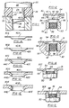
- Figure 1 illustrates one embodiment of a punch apparatus suitable for punching and forming a panel in accordance with the method of this invention.
- the punch apparatus includes a punch 20 having a body portion 22 and a punch portion 24.
- the punch portion 24 is cylindrical and has a diameter smaller than the diameter of the body portion 22 to receive a plastic spring member 26.
- the spring member 26 includes a cylindrical bore 28 which closely receives the cylindrical punch portion 24 of the punch.
- Plastic springs of the type shown in Figure 1 are commercially used for stripping the panel 30 from the punch and are sometimes referred to as a stripper. In the disclosed embodiment, however, the plastic spring functions not only as a stripper, but also deforms the metal panel in the die member 32, as described below. Such plastic springs are generally formed from a high density polyurethane.
- the die member 32 includes an annular die cavity 34 and a cylindrical bore 36 which receives the panel slug 38.
- the method steps performed by the apparatus shown in Figure 1 thus includes two steps.
- the cylindrical punch portion 24 punches a circular slug 38 from the panel 30, forming a circular opening or hole 42 in the panel.
- the panel is substantially simultaneously drawn and deformed into the annular die cavity 34 by the punch portion 24 and the plastic spring 26, forming a frusto-conical panel portion 40 adjacent the hole 42, as best shown in Figures 1A-1E discussed below.
- the panel may be drawn into the die cavity 34 and then punched or the steps may be separately performed.
- the panel slug 38 is removed through the cylindrical bore 36 of the die member.
- Figures 1A-1E illustrate cross-sections of panels of varying thickness punched and formed with the apparatus illustrated in Figure 1.
- the method of attaching a fastening element to a panel of this invention is suitable for attaching a fastening element to panels of different or varying thickness, such as utilized by the automotive industry.
- the panel shown in Figure 1A for example, has a thickness of 0.75-0.80 millimetres (mm).
- the panel illustrated in Figure 1E has a thickness of about 4 mm, which illustrates the range of panel thicknesses typically utilized by the automotive industry.
- Such panels are generally formed of steel, such as AISI 1008 or 1010 steel, which may be hot or cold rolled and are generally of commercial draw quality. Similar panels are used by many other industries.
- the appliance industry uses corrosion resistant and antimagnetic steels which are particularly suitable for the method of this invention because of their relatively poor weldability.
- Panels are used by the automotive industry for body panels, brackets and structural supports.
- the method of this invention may also be used to permanently install fastening elements in aluminium, copper and brass panels and other panels which require and installation of the type described herein. It is important to note, however, that the punch and forming apparatus shown in Figure 1 may be utilized to punch and form panels having a wide-range of panel thicknesses, such as illustrated in Figures 1A-1E.
- the thinner panels are punched and formed without extruding panel metal.
- a lip 44 is extruded axially by the punch portion 24, see 44C in Figure 1C, 44D in Figure 1D and 44E in Figure 1E. This extruded lip aids in the retention of the fastening element on the panel, as described below.
- the panel may also be punched and formed in separate operations on the frustoconical portion 40 may be formed in a configured die.
- the panel portion 40 may be characterized as frusto-conical shape or dome shape, wherein such terms are meant to include arcuate forms.
- FIGS 2-5 illustrate a female fastening element which may be installed in a panel 30 by the method of this invention.
- the term fastening element refers to a male or female fastening element preferably including a fastening portion, such as a threaded portion, which may be utilized to attach the panel to a second structural element, such as a panel, bracket or the like.
- Such fastening elements would therefore include a nut or bolt, as illustrated, and other fastening elements, including the male or female components of a ball joint and the like.
- the female fastening element or nut 50 illustrated in Figure 2 includes a body portion 52 and an annular or tubular barrel portion 54, preferably integral with the body portion and coaxially aligned with the threaded bore 56.
- the body portion 52 preferably includes an annular bearing face or surface 58, which preferably surrounds the tubular barrel portion 54, and a driven face 60.
- the free end 62 of the barrel portion 54 in the disclosed embodiment includes an annular internal chamber 64 and an arcuate outer surface 66.
- the internal surface 68 of the barrel portion is preferably smooth and the external surface 70 in the disclosed embodiment is cylindrical. As described below, however, the external surface 70 may be polygonal to provide improved torque resistance, including octagonal or hexagonal.
- the barrel portion 54 is preferably received through the panel hole 42 from adjacent the apex of the frusto-conical portion 40. That is, the fastening element is preferably received from the side of the panel opposite the side through which the punch 24 is received, as shown in Figure 1. Further, the diameter of the exterior surface 70 of the pilot portion is less than the internal diameter 42 of the domed panel. In the most preferred method, the barrel portion 54 is loosely received in the domed panel hole 42, reducing alignment problems.
- Figures 3-5 illustrate fastening element and panel assemblies which may be formed by the method of this invention.
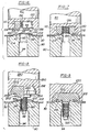
- FIGS. 6 and 7 illustrate an embodiment of an installation apparatus suitable for installing fastening elements of the type described.
- the installation apparatus includes a plunger 80 having a configured cavity 82, which receives and supports the nut 150, and a die member 90 which supports the panel 30 during installation of the fastening element and which deforms the pilot portion 154 radially outwardly to form a mechanical interlock with the panel 30, as now described.
- a plunger 80 having a configured cavity 82, which receives and supports the nut 150
- a die member 90 which supports the panel 30 during installation of the fastening element and which deforms the pilot portion 154 radially outwardly to form a mechanical interlock with the panel 30, as now described.
- U.S. Patents 4,543,701, 4,555,838 and 4,610,072 which disclose self-piercing and riveting fastening elements having a tubular barrel portion.
- the fastening element 150 illustrated in Figures 6, 7 and 10 - 14 may be identical to the fastener 50 illustrated in Figures 2 - 5, except that the female fastening element 150 includes radially projecting anti-rotation ribs 84 as best illustrated in Figures 6, 10 and 11.
- the anti-rotation ribs 84 are generally triangular and integrally joined to the bearing surface 158 of the body portion 152 and the external surface 170 of the barrel portion 154.
- the numbering of the elements of the female fastening element 150 is therefore the same sequence as the fastening element 50.
- the die member 90 is generally referred to as a die button.
- the die button 90 includes axial bores 92 and 94 which relieve pressure during the installation of the fastening element 150.
- the die face includes a central projecting die post 96 having a frusto-conical side face 98, a first flat annular surface 100 and a second flat annular surface 102, joined to the first annular surface 100 by a second conical surface 104.
- the pilot portion 154 is loosely received in the hole 42 through the panel and the annular bearing face 158 is then driven against the panel adjacent the hole 42, deforming the frusto-conical panel portion 40 to a generally planar configuration as shown in Figure 7.
- the panel is deformed into a radially projecting portion 110 and a conical portion 112.
- the tubular barrel portion 154 is simultaneously deformed radially outwardly, as now described.
- the inside chamber 164 at the free end of the barrel portion is first received against the conical surface 98 of the die button post followed by the inside surface 168 of the barrel portion. These surfaces are then received against the annular flat surface 100, forming a radially outwardly projecting lip 116, as shown in Figure 7.
- the annular surface 100 simultaneously deforms the radially projecting barrel portion 116 toward the bearing surface 158 of the body portion, squeezing the assembly and forming an intimate laminate comprising the radially projecting barrel portion 116, the radially projecting panel portion 110 and the bearing surface 158.
- a secure mechanical interlock is thus formed between the fastening element 150 and the panel 30.
- the internal diameter of the hole 42 in the panel 30 in the flattened condition shown in Figure 7 is less than the external diameter of the barrel portion 154.
- the radially projecting panel portion 110 is thus driven radially inwardly against the external surface of the barrel portion into the radially projecting ribs 84, driving the ribs into the panel.
- the tubular barrel portion resiliently resists radial deformation, driving the ribs into the radially projecting panel portion 110.
- the stress thus created is commonly referred to as hoop stress after the stress created by a barrel hoop or stay. That is, strain energy is directed radially inwardly against the barrel, which is resisted by the resilient tubular barrel portion.
- the barrel portion 154 may be polygonal and inserted into a circular hole.
- a circular hole is, however, preferred to avoid stress risers.
- FIGs 8 and 9 illustrate a method of installing a male fastening element 250.
- the male fastening element is installed in a relatively thin panel of approximately the same thickness as the panel 30 shown in Figures 6 and 7.
- the male fastening element 250 includes a tubular or annular barrel portion 254 having a free end 262 configured as described above in regard to the fastening element 50 in Figure 2.
- the body portion 252 of the male fastening element has been modified somewhat to provide an enlarged bearing surface 258 which will provide direct clamp loading of the fastener assembly, as will be understood by those skilled in the art.
- the male fastening element also includes a threaded shank or bolt portion 320 which is formed integrally with the fastener and coaxially aligned with the barrel portion 254.
- the plunger cavity 282 has been modified to conform to and receive the body portion 252 of the male fastening element; however, the installation of the male fastener element is substantially identical to the method described above in regard to Figures 6 and 7 and the die button 90 may be identical to the die button shown in Figures 6 and 7.
- the barrel portion 254 is first received through the hole 42 in the panel 30 and the bearing surface 258 is driven against the panel, deforming the panel into the generally planar configuration shown in Figure 9, including a radially projecting portion 210 and a generally conical portion 212.
- the barrel portion 254 is deformed radially outwardly by the conical face 98 and the flat 100, forming a radially projecting portion 216, as shown in Figure 9.
- the radially projecting panel portion 210 is driven into the radially projecting ribs 284, forming secure anti-rotation means.
- the method of installing the male fastener 250 is substantially identical to the method of installing the female fastener 150 as described above in regard to Figures 6 and 7.
- Figures 6 - 9 illustrate a fastening element installed "downwardly", wherein the fastening element 150 or 250 is received and retained in a plunger 80 or 280 and the plunger is driven downwardly to engage the fastening element with a die button 90.
- the fastening element may be installed upwardly as would be illustrated by turning Figures 6 - 9 upside down.
- the panel can be turned over after the panel is punched and formed as shown in Figure 1.
- the panel should be softer than the nut. Most preferably, the hardness of the panel should be less than about 60 % of the hardness of the nut.
- the fastening element should have hardness and strength characteristics typical of those fasteners which meet the requirements of ISO Classes 8 through 12.
- the fastener may be formed from AISI 1035 steel and heat treated to the appropriate hardness.
- the method of this invention may be utilized to install fastening elements in most panels used in mass production applications. Further, it is important to note that the same fastener may be installed in panels having a wide range of thicknesses using the same or very similar installation tooling.
- FIGs 10 - 14 illustrate important details of the method of attaching fastening elements to a panel, particularly a thickener panel, as shown in Figure 1E, above.
- the fastening element 150 has been described above in regard to Figure 6.
- the fastening element includes a tubular barrel portion 154 and a plurality of radially projecting ribs 84.
- the fastening element 150 is installed in a relatively thick panel 30E using the same tooling as used in the thin panel shown in Figure 6. That is, the fastening element is received and supported within a cavity 82 in a plunger or punch 80 and driven through the panel opening 42E against the conical side surface 98 of the die post.
- the bearing surface 158 of the body portion 152 first engages the extruded portion 44E and the ribs 84 begin to bite into the panel as shown in Figure 12. Finally, the annular die surface 100 is driven into the now radially projecting panel portion 110 and the free end 116 of the barrel portion is deformed radially outwardly as shown in Figure 13, forming a secure installation.
- the extruded metal 44E helps to fill the C-shaped radially outwardly opening annular cavity formed by the barrel portion 154 and bearing surface 158 as shown in Figure 13.
- Figure 14 illustrates the deformation of the panel 30 during the installation of the fastener 150.
- the hole 42 through the frusto-conical portion 40 has an inside diameter greater than the external diameter of the barrel portion 154, such that the barrel portion 154 is loosely received in the panel hole 42 during the installation of the fastening element.
- the panel is then deformed to a generally planar configuration, as shown, wherein the hole 42 has a diameter which is slightly less than the external diameter of the barrel portion 154.
- the panel is thus driven radially inwardly against the barrel portion during the final installation of the fastening element, improving the resistance to rotation of the fastening element in the panel.
- the method of attaching a fastening element of this invention may be utilized to install fastening elements to panels having a wide range of panel thicknesses using the same fastening element and tooling.
- the fastening element 50 is installed in a panel having an intermediate thickness such as shown, for example, in Figure 1B.
- the radially deformed barrel portion 54 is flush with the panel 30.
- the panel does include a slight emboss 31, but the emboss is substantially less than the emboss formed in most applications.
- Figure 5 illustrates an installation of the female fastener 50 in a relatively thick panel, such as a panel having a thickness of 4 mm.
- the panel 30E has no emboss and the barrel portion 54 is flush with the panel.
- Figures 7 and 9 illustrate the installation of both male and female fastening elements in a relatively thin panel, such as the panel shown in Figure 1B.
- the panel 30 does include a more substantial emboss, but the emboss is less than that formed by other methods and the radially deformed barrel portion 216 is flush or actually recessed in the panel 30.
- the method of installing a fastening element of this invention may be utilized to install both male and female fastening elements in panels having a relatively wide range of panel thicknesses.
- the fastening elements are installed in panels ranging in thickness from 0,75 mm to 4 mm.
- the push out strength was found to be more consistent with a wider range of panel thicknesses than prior methods discussed above.
- the fastening element and panel assembly shows improved torque resistance with thinner panels. For example, a 25 % increase in torque resistance was found in a 0.8 mm panel compared to the fastener and panel assembly shown in U.S. Patent 4,831,698.
- the method of permanently attaching a fastening element to a plastically deformable panel of this invention achieves the goals of the invention discussed above.
- the fastening element may have a polygonal barrel portion to further improve the torque resistance of the fastening element in the panel.
- the frusto-conical or dome-shaped portion 40 may be modified by using a configured die.
- the panel hole is enlarged during the doming step, such that the barrel portion is loosely received in the panel hole during the final installation step.
- the method of this invention will be particularly useful for such applications as safety bolt anchors for automotive seat belt installations, particularly, in thinner panel metals.
- the fastening element may be installed in very thin panel metals now being used by both the automotive and appliance industries. Thus, it is anticipated that the method of this invention will find a broad range of applications.
Description
- The present invention relates to a method of attaching a fastening element to a plastically deformable panel in accordance with the preamble of claim 1 and to an assembly of a plastically deformable panel and at least one fastening element in accordance with the preamble of claim 12. The preambles of claims 1 and 12 are based on the prior art of US-A-1,579,875.
- The present invention thus relates to methods of permanently attaching a fastening element, such as a nut or bolt, to a metal panel, and to the combination of a panel with at least one fastening element. The method of this invention is particularly useful for mass production applications, such as used by the automotive and appliance industries where a secure fastener installation is required in metal panels having a range of panel thicknesses. More specifically, the present invention relates to an improved riveting technique for flush mounting of a fastening element in panels having a range of panel thicknesses.
- Pierce nuts, such as disclosed in U.S. Patent No. 2,707,322, have been widely accepted in mass production applications such as the automotive industry. More recent improvements in pierce nuts, such as shown in U.S. Patent No. 3,648,747, have resulted in improved retention of the pierce nut in the panel, although the original universal pierce nut remains a preferred installation in many applications. In both types of pierce nuts, several nuts may be installed in a metal plate or panel wherein the plate or panel may be simultaneously formed into a contoured shape, such as an automotive body panel or structural support.
- More recently, fastening systems have been developed to permanently install both male and female fasteners in a panel in mass production applications, such as shown in U.S. Patent No. 4,555,838 and 4,610,072. The fastening element in such fastening systems include a tubular or annular barrel portion which is riveted to the panel during the installation. The tubular barrel portion may be utilized to pierce a slug from the panel, which may be received in the tubular barrel portion, as disclosed in U.S. Patent No. 4,55,838, or a punch may be utilized to pre-pierce the panel as disclosed, for example, in U.S. Patents 4,711,021, 4,831,698 and 4,713,872. Although such fasteners have achieved commercial success, the use of such fasteners in mass production applications has been somewhat limited by the range of panel thicknesses utilized by the automotive industry, for example, and in certain applications requiring improved torque resistance in thin panels.
- In the old proposal of US-A-1,579,875 dating from 1924, a frusto-conical depression is formed in a panel with an aperture at the narrow end of the depression. A nut element having a groove around its centre is inserted through the aperture so that a flange at one end of the element rests on the frusto-conical portion. The assembly is then pressed using a suitable die member so that the frusto-conical portion of the nut is contracted against the body of the nut within the groove which may include flats for anti-rotation purposes. In this arrangement, the nut element is not deformed and the engagement of the panel with the nut is not fully satisfactory. Another similar nut element is known from JP-A-3028514 in which the nut has a cylindrical projection which is inserted through the aperture in a frusto-conical depression in a panel and subsequently crimped to retain the element in the panel. It is stated that when the cylindrical projection is crimped deformation and strain will not be produced locally on the metal panel.
- This nut element and panel assembly is also not able to meet the stringent requirements required for some critical applications such as seat belt mountings in motor vehicles.
- The need remains for a universal fastening system utilizing conventional installation tooling which may be used for a wide-range of panel thicknesses and preferably having improved torque resistance. The improved fastener and panel assembly must also have good push out and pull through strength and be adapted for mass production applications.
- In order to satisfy this need there is provided a method and an assembly of the initially named kind having the characterising features of claims 1 and 12.
- The improved method of attaching a fastening element to a panel of this invention is thus particularly, but not exclusively adapted for permanent installation of fastening elements in plastically deformable metal panels having a range of panel thicknesses utilized in mass production applications, such as the automotive industry. The fastening element may be a female fastening element, such as a nut, or a male fastening element, such as a stud, bolt or the like. The fastening element includes a generally tubular barrel portion and preferably includes a body portion having a bearing surface surrounding the tubular barrel portion.
- The method of this invention includes forming a hole through the panel which is to receive the fastening element. The method further includes drawing and plastically deforming the panel into a generally dome-shaped or frusto-conical shaped portion surrounding the hole. The inside diameter of the hole is thus large enough to loosely receive the tubular barrel portion of the fastening element. The method then includes inserting the tubular barrel portion of the fastening element through the panel hole, preferably from adjacent the apex of the frusto-conical or dome-shaped portion and the method then includes plastically deforming the panel to a generally planar shape, thereby reducing the diameter of the hole to a diameter which is less than the external diameter of the tubular barrel portion. The panel surrounding the hole is thus driven into the tubular barrel portion, increasing the torque required to rotate the fastening element in the hole. Finally, the method includes plastically deforming the free end of the barrel portion radially outwardly, forming a mechanical interlock between the panel and the fastening element.
- In the most preferred method of this invention, the panel hole is formed by punching the panel with a cylindrical punch while the panel is supported on a die member. The panel is thus simultaneously drawn and deformed into the die member and punched, forming the dome or frusto-conical shaped portion of the panel surrounding the hole. Further, in the preferred method of this invention, the dome-shape portion of the panel is deformed by driving the annular bearing surface of the body portion of the fastening element against the panel surrounding the hole, deforming the panel into a generally planar shape, as described. The panel may be supported on a second die member or die button having an annular riveting surface, such that the panel is flattened and the fee end of the barrel portion is simultaneously deformed radially outwardly, forming the preferred mechanical interlock. In the most preferred method of this invention, the second die member further deforms the radially deformed barrel portion toward the bearing surface of the body portion of the fastening element, forming a substantially flush installation of the fastening element in the panel.
- The invention also comprises the combination of a panel and at least one fastener element as defined in claim 12. Such a combination may also be found in a finished product such as a motor car or washing machine incorporating one or more panels each provided with at least one fastener.
- The deformation of the material of the panel adjacent the aperture during fitting of the fastener will generally involve compressive stresses which lie above the yield stress of the panel material. Once plastic deformation of the panel material is completed in accordance with the present invention. Here will be a permanent residual compressive stress in the panel material surrounding the hole and the tubular body portion of the fastener, with this compressive stress typically and preferably lying just below the yield stress. Moreover the deformed panel portion will also exert a compressive force on the fastener element inducing a compressive stress in the latter.
- These locked in compressive stresses are a good protection against fatigue cracking in use. Moreover the compressive forces tightly restrain the fastener element against rotation under applied torque during assembly with a cooperating fastener element. Once assembly is complete high axial clamping forces losses such as usually arise with nut and bolt type fastener elements secure the assembly and friction between the axially clamped surfaces resists any applied torque which may be involved in the use of the panel component.
- Generally the radially deformed portion of the fastener element will lie flush with one side face of the panel so that this side face of the panel can lie flush with another panel and be pressed against it under the axial clamping load generated by a second fastener element cooperating with the first. In a relatively thinner panel the panel will generally include a residual frusto-conical portion after fitting of the fastener element to the panel. This residual frusto-conical portion ensures a high shear strength of the connection between the panel and the component mounted thereon via the fastener element. With a relatively thicker panel there is no longer a frusto-conical portion after fitting of the fastener but the residual compressive stress nevertheless ensures a good shear strength and fatigue strength of the connection.
- The torque resistance of the fastening element in the panel may be further improved by providing radially projecting ribs on the barrel portion and the method of this invention is uniquely adapted to provide improved torque resistance with such ribs. As described, the internal diameter of the hole is most preferably less than the external diameter of the tubular barrel portion when the panel is relatively flat. Thus, the panel portion surrounding the hole is driven into the barrel portion as the panel is deformed from a generally dome-shape to a generally planar shape. Where the tubular barrel portion includes radially projecting ribs, the panel is driven into the ribs, as the panel is flattened, and the tubular barrel portion resiliently drives the ribs into the panel. The resultant hoop stress or radially directed strain energy results in substantially improved torque resistance, which is an important advantage of the fastening element and panel assembly of this invention. The torque resistance may also be improved by using a split tubular riveting portion, although a continuous tube is preferred.
- Further, the same fastening element may be attached to metal panels having a relatively wide-range of different panel thicknesses using the same or similar installation tooling. Further, the fastening element barrel portion may be installed flush in the panel without a substantial embossure or bead. Thus, the method of installation of this invention provides the several advantages which are the objects of the invention. Other advantages and meritorious features of the method of this invention will be more fully understood from the following description of the preferred embodiments, the appended claims and the drawings, a brief description of which follows.
-
- Figure 1 is a side partially cross-sectioned view of an apparatus suitable for forming a hole in a panel and simultaneously forming a frusto-conical dome in the panel;
- Figures 1A-1E are panels of varying thickness formed by the punching apparatus shown in Figure 1;
- Figure 2 illustrates a female fastening element being received in a panel in the method of this invention;
- Figure 3 illustrates the fastening element and panel of Figure 2 during the installation of the fastener in the panel;
- Figure 4 illustrates the female fastening element and panel assembly attached as shown in Figures 2 and 3;
- Figure 5 is a side partially cross-sectioned view of a female fastening element and panel assembly similar to Figure 4, except with a thicker panel;
- Figures 6 and 7 illustrate the installation of a further embodiment of a female fastening element being installed in a relatively thin panel using one embodiment of an installation apparatus;
- Figures 8 and 9 illustrate the installation of one embodiment of a male fastening element in a panel using an installation apparatus similar to the installation apparatus shown in Figures 6 and 7;
- Figure 10 is an end view of the embodiment of the female fastening element shown in Figures 6 and 7;
- Figures 11 and 13 are partially cross-sectioned views of a female fastening element, panel and installation apparatus illustrating the installation of the female fastening element shown in Figure 10;
- Figure 12 is an enlarged partial cross-sectioned view of an intermediate step in the installation of the female element as shown in Figures 11 and 13; and
- Figure 14 is a partial cross-sectioned view, similar to Figures 6 and 7, illustrating the deformation of the panel during the installation of a fastening element.
- Figure 1 illustrates one embodiment of a punch apparatus suitable for punching and forming a panel in accordance with the method of this invention. The punch apparatus includes a
punch 20 having abody portion 22 and apunch portion 24. In the disclosed embodiment, thepunch portion 24 is cylindrical and has a diameter smaller than the diameter of thebody portion 22 to receive aplastic spring member 26. Thespring member 26 includes acylindrical bore 28 which closely receives thecylindrical punch portion 24 of the punch. Plastic springs of the type shown in Figure 1 are commercially used for stripping thepanel 30 from the punch and are sometimes referred to as a stripper. In the disclosed embodiment, however, the plastic spring functions not only as a stripper, but also deforms the metal panel in thedie member 32, as described below. Such plastic springs are generally formed from a high density polyurethane. - The
die member 32 includes anannular die cavity 34 and acylindrical bore 36 which receives thepanel slug 38. The method steps performed by the apparatus shown in Figure 1 thus includes two steps. Thecylindrical punch portion 24 punches acircular slug 38 from thepanel 30, forming a circular opening orhole 42 in the panel. The panel is substantially simultaneously drawn and deformed into theannular die cavity 34 by thepunch portion 24 and theplastic spring 26, forming a frusto-conical panel portion 40 adjacent thehole 42, as best shown in Figures 1A-1E discussed below. Depending upon the panel hardness and thickness, the panel may be drawn into thedie cavity 34 and then punched or the steps may be separately performed. Thepanel slug 38 is removed through the cylindrical bore 36 of the die member. - Figures 1A-1E illustrate cross-sections of panels of varying thickness punched and formed with the apparatus illustrated in Figure 1. As described above, the method of attaching a fastening element to a panel of this invention is suitable for attaching a fastening element to panels of different or varying thickness, such as utilized by the automotive industry. The panel shown in Figure 1A, for example, has a thickness of 0.75-0.80 millimetres (mm). The panel illustrated in Figure 1E has a thickness of about 4 mm, which illustrates the range of panel thicknesses typically utilized by the automotive industry. Such panels are generally formed of steel, such as AISI 1008 or 1010 steel, which may be hot or cold rolled and are generally of commercial draw quality. Similar panels are used by many other industries. The appliance industry uses corrosion resistant and antimagnetic steels which are particularly suitable for the method of this invention because of their relatively poor weldability. Panels are used by the automotive industry for body panels, brackets and structural supports. The method of this invention may also be used to permanently install fastening elements in aluminium, copper and brass panels and other panels which require and installation of the type described herein. It is important to note, however, that the punch and forming apparatus shown in Figure 1 may be utilized to punch and form panels having a wide-range of panel thicknesses, such as illustrated in Figures 1A-1E.
- As illustrated in Figures 1A and 1B, the thinner panels are punched and formed without extruding panel metal. In the thicker panels having a thickness greater than about 2.5 mm, a
lip 44 is extruded axially by thepunch portion 24, see 44C in Figure 1C, 44D in Figure 1D and 44E in Figure 1E. This extruded lip aids in the retention of the fastening element on the panel, as described below. As will be understood by those skilled in the art, the panel may also be punched and formed in separate operations on thefrustoconical portion 40 may be formed in a configured die. A configured die would, however, require a separate die for a much smaller range of panel thicknesses, which would be a disadvantage in mass production applications where panels of different thickness are routinely used. Thepanel portion 40 may be characterized as frusto-conical shape or dome shape, wherein such terms are meant to include arcuate forms. - Figures 2-5 illustrate a female fastening element which may be installed in a
panel 30 by the method of this invention. As used herein, the term fastening element refers to a male or female fastening element preferably including a fastening portion, such as a threaded portion, which may be utilized to attach the panel to a second structural element, such as a panel, bracket or the like. Such fastening elements would therefore include a nut or bolt, as illustrated, and other fastening elements, including the male or female components of a ball joint and the like. - The female fastening element or
nut 50 illustrated in Figure 2 includes abody portion 52 and an annular ortubular barrel portion 54, preferably integral with the body portion and coaxially aligned with the threaded bore 56. Thebody portion 52 preferably includes an annular bearing face orsurface 58, which preferably surrounds thetubular barrel portion 54, and a drivenface 60. Thefree end 62 of thebarrel portion 54 in the disclosed embodiment includes an annularinternal chamber 64 and an arcuateouter surface 66. Theinternal surface 68 of the barrel portion is preferably smooth and theexternal surface 70 in the disclosed embodiment is cylindrical. As described below, however, theexternal surface 70 may be polygonal to provide improved torque resistance, including octagonal or hexagonal. - In the method of this invention, the
barrel portion 54 is preferably received through thepanel hole 42 from adjacent the apex of the frusto-conical portion 40. That is, the fastening element is preferably received from the side of the panel opposite the side through which thepunch 24 is received, as shown in Figure 1. Further, the diameter of theexterior surface 70 of the pilot portion is less than theinternal diameter 42 of the domed panel. In the most preferred method, thebarrel portion 54 is loosely received in thedomed panel hole 42, reducing alignment problems. Figures 3-5 illustrate fastening element and panel assemblies which may be formed by the method of this invention. - Figures 6 and 7 illustrate an embodiment of an installation apparatus suitable for installing fastening elements of the type described. The installation apparatus includes a
plunger 80 having a configuredcavity 82, which receives and supports thenut 150, and adie member 90 which supports thepanel 30 during installation of the fastening element and which deforms thepilot portion 154 radially outwardly to form a mechanical interlock with thepanel 30, as now described. Reference may also be made to U.S. Patents 4,543,701, 4,555,838 and 4,610,072 which disclose self-piercing and riveting fastening elements having a tubular barrel portion. Thefastening element 150 illustrated in Figures 6, 7 and 10 - 14 may be identical to thefastener 50 illustrated in Figures 2 - 5, except that thefemale fastening element 150 includes radially projectinganti-rotation ribs 84 as best illustrated in Figures 6, 10 and 11. Theanti-rotation ribs 84 are generally triangular and integrally joined to thebearing surface 158 of thebody portion 152 and theexternal surface 170 of thebarrel portion 154. The numbering of the elements of thefemale fastening element 150 is therefore the same sequence as thefastening element 50. - The
die member 90 is generally referred to as a die button. In a disclosed embodiment, thedie button 90 includesaxial bores fastening element 150. The die face includes a central projecting diepost 96 having a frusto-conical side face 98, a first flatannular surface 100 and a second flatannular surface 102, joined to the firstannular surface 100 by a secondconical surface 104. As described above, thepilot portion 154 is loosely received in thehole 42 through the panel and theannular bearing face 158 is then driven against the panel adjacent thehole 42, deforming the frusto-conical panel portion 40 to a generally planar configuration as shown in Figure 7. The panel is deformed into aradially projecting portion 110 and aconical portion 112. - In the apparatus illustrated in Figures 6 and 7, the
tubular barrel portion 154 is simultaneously deformed radially outwardly, as now described. Theinside chamber 164 at the free end of the barrel portion is first received against theconical surface 98 of the die button post followed by the inside surface 168 of the barrel portion. These surfaces are then received against the annularflat surface 100, forming a radially outwardly projectinglip 116, as shown in Figure 7. Theannular surface 100 simultaneously deforms the radially projectingbarrel portion 116 toward the bearingsurface 158 of the body portion, squeezing the assembly and forming an intimate laminate comprising the radially projectingbarrel portion 116, the radially projectingpanel portion 110 and thebearing surface 158. A secure mechanical interlock is thus formed between thefastening element 150 and thepanel 30. - Further, as described above, the internal diameter of the
hole 42 in thepanel 30 in the flattened condition shown in Figure 7 is less than the external diameter of thebarrel portion 154. The radially projectingpanel portion 110 is thus driven radially inwardly against the external surface of the barrel portion into theradially projecting ribs 84, driving the ribs into the panel. Further, the tubular barrel portion resiliently resists radial deformation, driving the ribs into the radially projectingpanel portion 110. The stress thus created is commonly referred to as hoop stress after the stress created by a barrel hoop or stay. That is, strain energy is directed radially inwardly against the barrel, which is resisted by the resilient tubular barrel portion. It will be understood, however, that all applications do not require anti-rotation ribs and even a smooth barrel will provide some resistance to rotation because of the method of this invention. Further, thebarrel portion 154 may be polygonal and inserted into a circular hole. A circular hole is, however, preferred to avoid stress risers. - Figures 8 and 9 illustrate a method of installing a
male fastening element 250. As shown, the male fastening element is installed in a relatively thin panel of approximately the same thickness as thepanel 30 shown in Figures 6 and 7. Themale fastening element 250 includes a tubular orannular barrel portion 254 having afree end 262 configured as described above in regard to thefastening element 50 in Figure 2. Thebody portion 252 of the male fastening element has been modified somewhat to provide anenlarged bearing surface 258 which will provide direct clamp loading of the fastener assembly, as will be understood by those skilled in the art. Of course, the male fastening element also includes a threaded shank orbolt portion 320 which is formed integrally with the fastener and coaxially aligned with thebarrel portion 254. Theplunger cavity 282 has been modified to conform to and receive thebody portion 252 of the male fastening element; however, the installation of the male fastener element is substantially identical to the method described above in regard to Figures 6 and 7 and thedie button 90 may be identical to the die button shown in Figures 6 and 7. As shown in Figure 8, thebarrel portion 254 is first received through thehole 42 in thepanel 30 and thebearing surface 258 is driven against the panel, deforming the panel into the generally planar configuration shown in Figure 9, including aradially projecting portion 210 and a generallyconical portion 212. Thebarrel portion 254 is deformed radially outwardly by theconical face 98 and the flat 100, forming aradially projecting portion 216, as shown in Figure 9. The radially projectingpanel portion 210 is driven into theradially projecting ribs 284, forming secure anti-rotation means. Thus, the method of installing themale fastener 250 is substantially identical to the method of installing thefemale fastener 150 as described above in regard to Figures 6 and 7. - Figures 6 - 9 illustrate a fastening element installed "downwardly", wherein the
fastening element plunger die button 90. In mass production applications, where the fastening element may be installed in a progressive die, the fastening element may be installed upwardly as would be illustrated by turning Figures 6 - 9 upside down. Alternatively, the panel can be turned over after the panel is punched and formed as shown in Figure 1. In the preferred method of this invention, the panel should be softer than the nut. Most preferably, the hardness of the panel should be less than about 60 % of the hardness of the nut. The fastening element should have hardness and strength characteristics typical of those fasteners which meet the requirements of ISO Classes 8 through 12. The fastener may be formed from AISI 1035 steel and heat treated to the appropriate hardness. Thus, the method of this invention may be utilized to install fastening elements in most panels used in mass production applications. Further, it is important to note that the same fastener may be installed in panels having a wide range of thicknesses using the same or very similar installation tooling. - Figures 10 - 14 illustrate important details of the method of attaching fastening elements to a panel, particularly a thickener panel, as shown in Figure 1E, above. The
fastening element 150 has been described above in regard to Figure 6. The fastening element includes atubular barrel portion 154 and a plurality of radially projectingribs 84. As shown in Figure 11, thefastening element 150 is installed in a relativelythick panel 30E using the same tooling as used in the thin panel shown in Figure 6. That is, the fastening element is received and supported within acavity 82 in a plunger or punch 80 and driven through thepanel opening 42E against theconical side surface 98 of the die post. The bearingsurface 158 of thebody portion 152 first engages the extrudedportion 44E and theribs 84 begin to bite into the panel as shown in Figure 12. Finally, theannular die surface 100 is driven into the now radially projectingpanel portion 110 and thefree end 116 of the barrel portion is deformed radially outwardly as shown in Figure 13, forming a secure installation. The extrudedmetal 44E helps to fill the C-shaped radially outwardly opening annular cavity formed by thebarrel portion 154 and bearingsurface 158 as shown in Figure 13. - Figure 14 illustrates the deformation of the
panel 30 during the installation of thefastener 150. As shown in Figure 14, thehole 42 through the frusto-conical portion 40 has an inside diameter greater than the external diameter of thebarrel portion 154, such that thebarrel portion 154 is loosely received in thepanel hole 42 during the installation of the fastening element. The panel is then deformed to a generally planar configuration, as shown, wherein thehole 42 has a diameter which is slightly less than the external diameter of thebarrel portion 154. As described above, the panel is thus driven radially inwardly against the barrel portion during the final installation of the fastening element, improving the resistance to rotation of the fastening element in the panel. - It should now be evident to a person skilled in the art, comparing the fastening element and panel installation shown in Figures 4, 5, 7 and 9, that the method of attaching a fastening element of this invention may be utilized to install fastening elements to panels having a wide range of panel thicknesses using the same fastening element and tooling. As shown in Figures 3 and 4, the
fastening element 50 is installed in a panel having an intermediate thickness such as shown, for example, in Figure 1B. The radiallydeformed barrel portion 54 is flush with thepanel 30. The panel does include aslight emboss 31, but the emboss is substantially less than the emboss formed in most applications. Figure 5 illustrates an installation of thefemale fastener 50 in a relatively thick panel, such as a panel having a thickness of 4 mm. Thepanel 30E has no emboss and thebarrel portion 54 is flush with the panel. Finally, Figures 7 and 9 illustrate the installation of both male and female fastening elements in a relatively thin panel, such as the panel shown in Figure 1B. Thepanel 30 does include a more substantial emboss, but the emboss is less than that formed by other methods and the radiallydeformed barrel portion 216 is flush or actually recessed in thepanel 30. - Thus, the method of installing a fastening element of this invention may be utilized to install both male and female fastening elements in panels having a relatively wide range of panel thicknesses. In the illustrated embodiments, the fastening elements are installed in panels ranging in thickness from 0,75 mm to 4 mm. In testing of the fastening element and panel assembly, the push out strength was found to be more consistent with a wider range of panel thicknesses than prior methods discussed above. More importantly, the fastening element and panel assembly shows improved torque resistance with thinner panels. For example, a 25 % increase in torque resistance was found in a 0.8 mm panel compared to the fastener and panel assembly shown in U.S. Patent 4,831,698. Thus, the method of permanently attaching a fastening element to a plastically deformable panel of this invention achieves the goals of the invention discussed above.
- As will be understood, various modifications may be made to the disclosed male and female fastening elements, installation tooling and method disclosed and described in regard to Figures 1 - 14, without departing from the purview of the invention as defined in the claims. For example, the fastening element may have a polygonal barrel portion to further improve the torque resistance of the fastening element in the panel. The frusto-conical or dome-shaped
portion 40 may be modified by using a configured die. However, in the preferred method of this invention, the panel hole is enlarged during the doming step, such that the barrel portion is loosely received in the panel hole during the final installation step. Thus, the method of this invention will be particularly useful for such applications as safety bolt anchors for automotive seat belt installations, particularly, in thinner panel metals. Further, the fastening element may be installed in very thin panel metals now being used by both the automotive and appliance industries. Thus, it is anticipated that the method of this invention will find a broad range of applications.
Claims (21)
- A method of attaching a fastening element (50, 150, 250) to a plastically deformable panel (30), said fastening element including a hollow portion, said method comprising:(a) forming a hole (42) through said panel;(b) drawing and plastically deforming said panel (30) into a generally dome-shaped portion (40) surrounding said hole (42) with said hole at a smaller diameter of said dome-shaped portion;(c) inserting said hollow portion of said fastening element (50, 150, 250) through said panel hole (42);(d) plastically deforming said panel dome-shaped portion thereby reducing the diameter of said hole (42) and the surrounding panel into engagement with said hollow portion;characterised in that
the internal diameter of the hole (42) is less than the external diameter of the hollow portion when the panel is relatively flat, said hollow portion being formed as a generally tubular barrel portion (54, 154, 254);
in that said panel dome-shaped portion (40) is deformed into a generally planar shape; and in that an end of said generally tubular barrel portion (54, 154, 254) is simultaneously plastically deformed radially outwardly forming a mechanical interlock between said panel (30) and said fastening element (50, 150, 250). - A method as defined in claim 1, wherein said hole (42) is formed by punching said panel (30) with a generally cylindrical punch (24), said panel (30) being supported on a die element (32), said panel (30) thus being simultaneously drawn and deformed into said dome-shaped portion (40) in said die element (32) and punched to form said hole.
- A method as defined in claim 1 or claim 2, wherein said fastening element includes a body portion (52, 152, 252) and said barrel portion (54, 154, 254) extending from said body portion, said body portion including an annular bearing surface (58, 158, 258) surrounding said barrel portion (54, 154, 254) having a diameter greater than said panel hole (42), said method including inserting said barrel portion (54, 154, 254) into said panel hole (42) from adjacent said smaller diameter of said dome-shaped panel portion and driving said annular driving surface (58, 158, 258) against said panel adjacent said hole, thereby deforming said dome-shaped panel portion (40) to said generally planar shape,
wherein said barrel portion (54, 154, 254) is preferably received through said panel hole (40) into a die member (90), said method preferably including driving said fastening element bearing surface against said panel to deform said panel (30) and substantially simultaneously deforming said barrel portion (54, 154, 254) radially outwardly in said die member (90),
said die member (90) preferably including a central post (96) having a projecting end portion and a generally conical side surface (98) receiving an inside surface of said tubular barrel portion, said conical surface, deforming said free end of said barrel portion radially outwardly (116, 216) and entrapping a radially projecting portion (110, 210) of said panel (30) adjacent said hole between said radially deformed free end (116, 216) of said barrel portion and said bearing surface of said body portion; and
wherein said method optionally further includes pressing said barrel portion free end (116, 216) toward said bearing surface (58, 158, 258) thereby squeezing said radially projecting panel portion (110, 210), forming an intimate laminate and a substantially flush installation of said fastening element (50, 150, 250) in said panel (30). - A method as defined in claim 1, said panel being a plastically deformable metal panel, said fastening element including a body portion (52, 152, 252) having an annular bearing surface (58, 158, 258) surrounding said tubular barrel portion (54, 154, 254), said method comprising further the steps ofinserting said tubular barrel portion (54, 154, 254) through said hole from adjacent the apex of said generally frusto-conical portion (40) and said bearing surface (58, 158, 258) of said body portion (54, 154, 254) engaging a panel portion surrounding said panel hole; anddriving said body portion annular bearing surface (58, 158, 258) of said fastening element against said panel portion surrounding said hole to plastically deform said panel frusto-conical portion (40) to said generally planar shape and substantially simultaneously effecting said plastic deformation of a projecting free end (116, 216) of said tubular barrel portion (54, 154, 254) radially outwardly thus entrapping said panel portion (40) between said annular bearing surface (58, 158, 258) and said radially deformed free barrel portion end (116, 216).
- A method as defined in claim 4, wherein said panel is supported on a die element (32) having an annular die cavity (34), said method including driving a punch (20) against said panel (30), deforming and drawing said panel (30) into said die member cavity (34) into said frusto-conical panel portion and punching a hole (42) in said panel (30).
- A method as defined in claim 5, wherein said punch (20) forms an axially projecting lip (44C, 44D, 44E) surrounding said hole (42), said method including driving said bearing surface (58, 158, 258) against said lip and deforming said lip (44C, 44D, 44E) between said bearing surface (58, 158, 258) and said radially deformed barrel portion (54, 154, 254).
- A method as defined in any one of claims 1 to 6, wherein said step of drawing and plastically deforming said panel (30) into a generally dome-shaped portion (40) comprises forcing a plastic spring member (26) against said panel (30) adjacent said hole (42).
- A method as defined in any one of claims 4 to 6, wherein said frusto-conical panel portion (40) is received and supported on a die member (90), said die member (90) including a central die post (96) having a projecting end portion coaxially aligned with said fastening element tubular barrel portion and a conical side surface (98) receiving an inside surface (68, 168) of said tubular barrel portion (54, 154, 254), said conical die surface deforming a free end (116, 216) of said barrel portion radially outwardly, entrapping a radially extending portion (110, 210) of said panel adjacent said panel hole between said radially deformed barrel portion free end (116, 216) and said body portion annular bearing surface (58, 158, 258), said method preferably comprising the further step of pressing said barrel portion free end (116, 216) toward said bearing surface (58, 158, 258), thereby squeezing said panel (30) and forming an intimate laminate comprising said barrel portion free end (116, 216), said panel (30) and said bearing surface (58, 158, 258).
- A method as defined in claim 1,
said panel being in the form of a metal panel having a thickness within a range of panel thicknesses, said fastening element (50, 150, 250) having a body portion (52, 152, 252) having a bearing face (58) 158, 258) on at least opposed sides of said barrel portion, said method comprising the further steps ofloosely receiving said barrel portion in said panel hole by inserting a free end (116, 216) of said barrel portion through said panel hole and of driving said fastening element body portion bearing face (58, 158, 258) against a panel portion (40) adjacent said hole, to deform said conical panel portion (40) to said substantially planar shape,wherein said fastening element barrel portion includes a plurality of spaced radially projecting ribs (84, 284) adjacent said bearing face, and said method includes driving said panel portion (40) radially into said ribs as said conical panel portion (40) is deformed to said generally planar shape and said tubular barrel portion (54, 154, 254) elastically driving said ribs into said panel portion, to forming secure anti-rotation means between said fastening element and said panel; and wherein said method further includes pressing said barrel portion free end (116, 216) toward said bearing surface (58, 158, 258) of said body portion, thereby squeezing said panel portion (40) and forming an intimate laminate of said radially deformed barrel portion free end (116, 216), a radially projecting panel portion (110, 210) and said bearing surface (58, 158, 258) of said body portion. - A method as defined in claim 9, wherein said hole (42) is formed by a punch (20) while said panel is supported on a die member (32) having an annular die cavity (34), said punch punching a hole (42) in said panel and simultaneously plastically deforming and drawing said panel (30) surrounding said hole in said die member die cavity into said generally conical shaped portion (40).
- A method as defined in claim 9 or claim 10, wherein said method includes driving said fastening element body portion bearing surface (58, 158, 258) against said panel portion adjacent said hole, deforming said conical panel portion (40) to a generally planar shape and substantially simultaneously deforming said free end (116, 216) of said tubular barrel portion (54, 154, 254) radially outwardly to form said mechanical interlock.
- An assembly of a plastically deformable panel (30) and at least one fastening element (50, 150, 250) having a body portion (52) at one side of said panel (30), a hollow portion passing through an aperture (42) in said panel (30) and a radially extending portion (116, 216) at the opposite side of said panel from said body portion thus forming a mechanical interlock between said panel (30) and said fastening element (50, 150, 250), with said body portion (52, 152, 252) having a side wall and a bearing surface (58, 158, 258) extending between said side wall and said hollow portion, wherein said fastening element comprises a riveting fastener including said body portion (52, 152, 252) and a tubular riveting barrel portion (54, 154, 254) having a free end (62) and defining said hollow portion and said radially extending portion (116, 216), with said tubular barrel portion being received through said panel opening (42) and said barrel portion free end (62) being radially deformed to engage said panel and to pinch said panel (30) between said radially deformed barrel portion (54, 154, 254) and said bearing surface (58, 158, 258), characterised in that said portion of said panel pinched between said deformed barrel portion and said bearing surface is a plastically deformed panel portion and extends generally parallel to said bearing surface (58, 158, 258) which is a radial surface, and in that the material of said panel (30) adjacent said aperture has a permanent compressive hoop stress preferably lying just below the yield stress of said plastically deformable material.
- An assembly in accordance with claim 12, characterised in that said panel (30) exerts a permanent compressive force on at least a major portion of the surface (70 and/or 116, 216; 58, 158, 258) of said fastener in mechanical interlocking engagement with said panel.
- An assembly in accordance with claim 12 or claim 13, characterised in that said one side of said panel (30) is coplanar with an outer surface of said radially deformed portion (116, 216) so that said radially deformed portion does not project beyond said one side in the direction away from said opposite side.
- An assembly in accordance with claim 14, when used in combination with said one side of said panel (30) adjacent a side of a further panel lying parallel to it and secured thereto, at least in part, by a fastening element cooperating with said at least one fastener (50, 150, 250).
- An assembly in accordance with any one of claims 12 to 15, characterised in that said aperture (42) in said panel (30) is formed in a portion of said panel which merges via a substantially frusto-conical portion (31, 112, 212) of said panel into the remainder of said panel (30), with said radially deformed portion (116, 216) of said fastener lying generally within said frusto-conical portion.
- An assembly in accordance with any one of claims 12 to 16, characterised in that said fastener has a barrel portion (54, 154, 254) received in said aperture and is provided with formations such as radially projecting rounded ribs (84, 284) or corners, e.g. corners of a generally polygonally shaped barrel portion.
- An assembly in accordance with any one of the preceding claims 12 to 17, characterised in that the hardness of said panel (30) is less than about 60% of the hardness of the fastener (50, 150, 250).
- An assembly in accordance with one of the preceding claims 12 to 18, wherein said riveting fastener comprises a stud portion (320) in addition to said tubular riveting barrel portion (254) and said body portion (252), said tubular barrel portion (254) extending from said body portion (252) and encircling said stud portion (320).
- The use of a riveting stud fastener in the method of claim 1,
said fastener comprisingan elongated body member (320) and a head portion (252), said elongated body integrally joined to and extending from said head portion (252), said head portion including a tubular barrel portion (254) encircling said elongated member (320),said head portion (252) further including an annular trough encircling said tubular barrel portion (254), wherein a portion of said trough surface defines a radial bearing surface (258), and wherein said head portion includes projections (284) extending from said radial bearing surface. - The use of a hollow nut fastener in the method of claim 1, said fastener comprising a body portion (52, 152), a tubular barrel portion (54, 154) extending from said body portion, said body portion (52, 152) having a radially directed annular bearing surface (58, 158) surrounding said tubular barrel portion, and a plurality of radially directed antirotation ribs (84) at the transition from said annular bearing surface (58, 158) into the barrel portion (54, 154), characterised in that the nut fastener has a tubular barrel portion having a length adapted for use with a panel having a thickness in the range from 0.75 mm to 4.0 mm whereby, with thinner panels of 0.75mm thickness or greater, but less than 4.0 mm thickness the barrel portion is plastically deformed radially outwardly to form a radially directed flange (54, Figs. 3 and 4) spaced from said radially directed annular bearing surface (58, 158) by a distance equal to the thickness of said panel and terminates in said radially directed flange, whereas with thicker panels of 4.0 mm the barrel portion is plastically deformed into and terminates in a conically diverging lip (54, Fig. 5) spaced from said radially directed annular bearing surface by a maximum distance less than the thickness of the panel.
Applications Claiming Priority (2)
| Application Number | Priority Date | Filing Date | Title |
|---|---|---|---|
| US786204 | 1991-10-31 | ||
| US07/786,204 US5251370A (en) | 1991-10-31 | 1991-10-31 | Method of attaching a fastening element to a panel |
Publications (2)
| Publication Number | Publication Date |
|---|---|
| EP0539793A1 EP0539793A1 (en) | 1993-05-05 |
| EP0539793B1 true EP0539793B1 (en) | 1996-12-27 |
Family
ID=25137890
Family Applications (1)
| Application Number | Title | Priority Date | Filing Date |
|---|---|---|---|
| EP92117466A Expired - Lifetime EP0539793B1 (en) | 1991-10-31 | 1992-10-13 | Method of attaching a fastening element to a panel and combination of a panel and at least one fastening element |
Country Status (7)
| Country | Link |
|---|---|
| US (2) | US5251370A (en) |
| EP (1) | EP0539793B1 (en) |
| JP (1) | JP3452203B2 (en) |
| KR (1) | KR100249118B1 (en) |
| CA (1) | CA2081688C (en) |
| DE (1) | DE69216206T2 (en) |
| ES (1) | ES2096002T3 (en) |
Cited By (8)
| Publication number | Priority date | Publication date | Assignee | Title |
|---|---|---|---|---|
| DE102004043688A1 (en) * | 2004-06-23 | 2006-04-06 | Profil-Verbindungstechnik Gmbh & Co. Kg | Method for producing an assembly part consisting of a sheet metal part and a functional element attached thereto, sheet metal part and functional element |
| US7155798B2 (en) | 2003-07-25 | 2007-01-02 | Profil Verbindungstechnik Gmbh & Co. Kg | Method for the attachment of a functional element to a sheet metal part and also a component assembly |
| WO2007065398A1 (en) | 2005-12-09 | 2007-06-14 | Heiko Schmidt | Method of attaching a functional element to a flat material and connection between a functional element and a flat material |
| WO2008138315A2 (en) | 2007-05-14 | 2008-11-20 | Heiko Schmidt | Method for application of a joint or function element to a planar material rivet connection and joint or function element |
| US7815406B2 (en) | 2004-12-23 | 2010-10-19 | Profil Verbindungstechnik Gmbh & Co., Kg | Element attachable by riveting to a sheet metal part and also a component assembly and a method for the production of the component assembly |
| US8210315B2 (en) | 2008-02-29 | 2012-07-03 | Profil Verbindungstechnik Gmbh & Co., Kg | Component assembly comprising a sheet metal part and a nut element attached thereto and also a method for the manufacture of such a component assembly |
| DE102011104971A1 (en) | 2011-06-20 | 2012-12-20 | Profil Verbindungstechnik Gmbh & Co. Kg | One-piece hollow functional element for conveying and sorting equipment used in industry, has rivet elements that are arranged symmetrically with respect to plane perpendicular to longitudinal axis such that two rivets are identical |
| DE102011108987A1 (en) | 2011-08-01 | 2013-02-07 | Thyssenkrupp System Engineering Gmbh | Method for cupping work piece by tool, particularly hand tool, involves providing opening in cupping step with work piece, where cup die-plate is arranged on side of work piece in another cupping step |
Families Citing this family (90)
| Publication number | Priority date | Publication date | Assignee | Title |
|---|---|---|---|---|
| US5564873A (en) * | 1980-02-02 | 1996-10-15 | Multifastener Corporation | Self-attaching fastening element and method of attachment |
| US5722139A (en) * | 1981-01-28 | 1998-03-03 | Multifastener Corporation | Installation apparatus for attaching a fastener to a panel |
| DE4410475A1 (en) * | 1994-03-25 | 1995-09-28 | Profil Verbindungstechnik Gmbh | Rivetable element, assembly part with a rivetable element as well as rivet die and method for producing the assembly part |
| US5528812A (en) * | 1991-10-31 | 1996-06-25 | Profil-Verbindungstechnik Gmbh & Co. Kg | Method of attaching a fastener to a plurality of panels |
| SK283908B6 (en) * | 1992-07-07 | 2004-04-06 | Richard Bergner Gmbh & Co. | Insert for use as connection element for joints designed to be secure against rotation and insert ejection |
| US6125524A (en) * | 1994-03-25 | 2000-10-03 | Multifastener Corporation | Rivetable element, assembly, method of assembly and riveting die |
| JP3670714B2 (en) * | 1994-05-31 | 2005-07-13 | Ntn株式会社 | Joint structure of constant velocity joint outer ring and shaft |
| DE4444908A1 (en) * | 1994-12-16 | 1996-06-27 | Hilti Ag | Fastener |
| JP3090588B2 (en) * | 1995-05-12 | 2000-09-25 | 株式会社ソミック石川 | Ball joint |
| US5711549A (en) * | 1995-06-07 | 1998-01-27 | Itt Automotive, Inc. | High pressure quick connect for use in automotive brake system application |
| US5713116A (en) * | 1995-07-13 | 1998-02-03 | Penn Engineering & Manufacturing Corp. | Clinch-type lock nut installation and formation process |
| US5882159A (en) * | 1996-08-16 | 1999-03-16 | Profil Verbindungstechnik, Gmbh & Co. | Element, method of attaching the element to a plate-like component, component assembly and die button |
| DE19612619C2 (en) * | 1996-03-29 | 2001-07-26 | Hecralmat Schaan Fa | Process for producing a hole reinforcement in a sheet by means of a disc, and hole reinforcement |
| IT1285832B1 (en) * | 1996-03-29 | 1998-06-24 | Roltra Morse Spa | REINFORCED FIXING POINT |
| US5882049A (en) * | 1996-12-18 | 1999-03-16 | Itt Automotive, Inc. | High pressure quick connect with reduced volumetric displacement and piloted snap ring |
| US5839848A (en) * | 1996-12-30 | 1998-11-24 | Sahramaa; Kimmo J | Joining metal members |
| US6113151A (en) * | 1998-01-27 | 2000-09-05 | Itt Manufacturing Enterprises, Inc. | High pressure quick connect and production process therefor |
| CN1290197A (en) * | 1998-02-17 | 2001-04-04 | 科西马国际公司 | Self-extruded bushing assembly and method for making the same |
| SE523534C2 (en) * | 1998-03-10 | 2004-04-27 | Oehlins Racing Ab | Valve or pressure regulator device for effecting opening and / or closing functions or movements for two parts working against each other, eg cone / slide and seat / housing respectively. |
| DE19832150A1 (en) * | 1998-07-17 | 2000-01-20 | Bosch Gmbh Robert | Sealing disk for pre-fitting to shaft or casing, made of permanently deformable material |
| US6412826B1 (en) | 1999-04-16 | 2002-07-02 | Itt Manufacturing Enterprises, Inc. | High pressure quick connector |
| US7731467B2 (en) * | 1999-07-09 | 2010-06-08 | Profil Verbindungstechnik Gmbh & Co., Kg | Bolt element having a shaft part and a spherical head, component assembly and method for the manufacture of a bolt element |
| AU775346B2 (en) * | 1999-10-14 | 2004-07-29 | Johann Gersbach | Belt fasteners |
| DE60025300T2 (en) * | 1999-10-18 | 2006-09-21 | Kabushiki Kaisha Yutaka Giken, Hamamatsu | Rivet connection and method to connect two parts by means of rivets |
| EP1132236B1 (en) * | 2000-03-10 | 2005-05-11 | Arvinmeritor Light Vehicle Systems-France | Method and apparatus for mounting a drive mechanism within a door module |
| US6517344B2 (en) * | 2000-05-26 | 2003-02-11 | Brass-Craft Manufacturing Company | Gas supply coupling for water heater |
| US6474918B1 (en) * | 2000-06-30 | 2002-11-05 | Ashton Plastic Products, Inc. | Anti-cross threading device |
| GB0030097D0 (en) * | 2000-12-09 | 2001-01-24 | Meritor Light Vehicle Sys Ltd | Assembly |
| KR100901840B1 (en) | 2000-12-29 | 2009-06-09 | 프로필 페르빈둥스테크닉 게엠베하 운트 컴파니 카게 | Bolt element comprising a shaft part and a spherical head |
| DE10104549A1 (en) * | 2001-02-01 | 2002-08-08 | Profil Verbindungstechnik Gmbh | Method for attaching a functional element to a deformable metal part using a high pressure forming method, assembly part and die |
| DE10243759B4 (en) | 2002-09-20 | 2011-08-11 | PROFIL Verbindungstechnik GmbH & Co. KG, 61381 | Method for producing an electrically conductive connection between an electrical connection device such as a cable lug and a sheet metal part, fastening element and assembly component |
| DE10114200A1 (en) | 2001-03-23 | 2002-09-26 | Profil Verbindungstechnik Gmbh | Fastener, for use with sheet metal, has annular head connected to tubular rivet section which has guide section at its base projecting below rivet section with annular gap between two sections |
| DE10117060A1 (en) * | 2001-04-05 | 2002-10-10 | Profil Verbindungstechnik Gmbh | Method for attaching a functional element to a component and associated tool |
| US6453558B1 (en) * | 2001-04-06 | 2002-09-24 | Arvinmeritor, Inc. | Method of locking together exhaust components |
| DE10118149A1 (en) * | 2001-04-11 | 2002-10-17 | Profil Verbindungstechnik Gmbh | Method to fasten functional element to sheet metal part uses die plate with and rivet part with self-punching action for secure connection |
| DE10119505A1 (en) | 2001-04-20 | 2002-10-24 | Profil Verbindungstechnik Gmbh | Functional part has main body with annular flange leading into cylindrical rivet part and in-between conical surface, sheet metal part and locking part |
| US7124492B2 (en) * | 2001-07-19 | 2006-10-24 | Whitesell International Corporation | Fastener, method of attaching a fastener to a panel and fastener and panel assembly |
| US7698799B2 (en) * | 2001-07-19 | 2010-04-20 | Whitesell International Corporation | Method of attaching a clinch spacer to a panel |
| US6592311B2 (en) | 2001-07-19 | 2003-07-15 | Fabristeel Products, Inc. | Double-ended self-attaching stud |
| US8092131B2 (en) * | 2001-07-19 | 2012-01-10 | Whitesell International Corporation | Clinch spacer and method of attaching the same to a panel |
| US6491487B1 (en) * | 2001-07-19 | 2002-12-10 | Fabristeel Products, Inc. | Double-ended self-attaching stud |
| ATE460593T1 (en) * | 2001-08-15 | 2010-03-15 | Whitesell Int Corp | SELF-ATTACHING FASTENING ELEMENT |
| US7516534B2 (en) * | 2001-11-25 | 2009-04-14 | Stresswave, Inc. | Method for attaching a nut element to a metal structure |
| DE60214434T2 (en) | 2002-01-22 | 2007-08-30 | Whitesell International Corp., Taylor | SELF-THRUSTER FASTENING NUT AND METHOD FOR PRODUCING SEALED PANEL ASSEMBLY WITH SUCH FIXING NUTS |
| MXPA04007095A (en) * | 2002-01-22 | 2004-10-29 | Fabristeel Prod Inc | Method of cold forming a self-attaching female fastener element. |
| BR0202511A (en) * | 2002-07-03 | 2004-05-11 | Manegro Administracao E Partic | Pipe and equipment flange gasket, gasket manufacturing process, and gasket for gasket |
| US20040146375A1 (en) * | 2002-08-30 | 2004-07-29 | Ward Richard P. | Self-attaching nut |
| US7112024B2 (en) * | 2002-08-30 | 2006-09-26 | Whitesell International Corporation | Self-attaching nut |
| US6851904B2 (en) | 2002-08-30 | 2005-02-08 | Fabristeel Products, Inc. | Self-attaching female fastener and method of installation |
| US7591623B2 (en) * | 2002-08-30 | 2009-09-22 | Whitesell International Corporation | Heavy metal pierce nut |
| US20040042871A1 (en) | 2002-09-04 | 2004-03-04 | Wojciechowski Stanley E. | Self-attaching female fastener element, sealed fastener and panel assembly and method of forming same |
| US20050111934A1 (en) * | 2003-11-14 | 2005-05-26 | Ladouceur Harold A. | Self-riveting male fastener and panel assembly |
| WO2004038235A1 (en) * | 2002-10-23 | 2004-05-06 | Fabristeel Products, Inc. | Self-attaching female fasteners and method of forming female fastener elements |
| WO2004037481A1 (en) * | 2002-10-23 | 2004-05-06 | Fabristeel Products, Inc. | Self-attaching female fastener element and method of installation |
| DE102004004384B4 (en) * | 2004-01-29 | 2006-05-18 | Daimlerchrysler Ag | Method and device for fastening a rivet nut to a workpiece |
| GB0406390D0 (en) * | 2004-03-22 | 2004-04-21 | Bas Components Ltd | Vehicle roofrack mounting |
| DE102004017866A1 (en) * | 2004-04-13 | 2005-11-03 | Profil-Verbindungstechnik Gmbh & Co. Kg | Process for the production of hollow body elements, hollow body element, assembly component and follow-on composite tool for carrying out the method |
| DE102004020675A1 (en) * | 2004-04-28 | 2005-11-24 | Profil Verbindungstechnik Gmbh & Co. Kg | Method and device for attaching a fastener to a component, in particular to a sheet metal part |
| DE102004030223A1 (en) * | 2004-06-23 | 2006-01-12 | Profil Verbindungstechnik Gmbh & Co. Kg | Flat metal part to be stationary joined to module, comprising impressions serving as locking areas |
| US7480971B2 (en) | 2005-04-28 | 2009-01-27 | Profile Verbindungstechnik Gmbh & Co., Kg | Method and device for mounting a fastener element on a part, particularly a sheet metal part |
| DE102005024220A1 (en) * | 2005-05-25 | 2006-11-30 | Profil Verbindungstechnik Gmbh & Co. Kg | Method for producing hollow body elements, hollow body element, assembly component, progressive composite tool for producing hollow body elements and rolling mill |
| RU2418206C2 (en) * | 2006-01-05 | 2011-05-10 | Профиль-Фербиндунгстехник Гмбх Унд Ко. Кг | Fastening element, subassembly, made of fastening element and sheet metal parts, and also method to fix fastening element onto sheet metal parts |
| JP5148074B2 (en) * | 2006-05-24 | 2013-02-20 | プロフィル・フェルビンドゥングステヒニック・ゲーエムベーハー・ウント・コンパニー・カーゲー | Member and part assembly that can be attached to sheet metal part by riveting, and method for manufacturing the part assembly |
| DE202006008721U1 (en) * | 2006-06-01 | 2007-10-11 | Profil Verbindungstechnik Gmbh & Co. Kg | Rivet nut and combination of a rivet nut with a sheet metal part |
| DE102006050640A1 (en) * | 2006-10-26 | 2008-04-30 | Profil-Verbindungstechnik Gmbh & Co. Kg | Fastening element has head part with metallic contact surface, and metallic sheet thickness corresponds to axial height between head part and rivet section |
| CN101210582A (en) * | 2006-12-28 | 2008-07-02 | 鸿富锦精密工业(深圳)有限公司 | Double-ended bolt |
| WO2008138286A2 (en) * | 2007-05-14 | 2008-11-20 | Heiko Schmidt | Method for application of a joint or function element to a planar material and joint or function element |
| US8608420B2 (en) * | 2007-08-24 | 2013-12-17 | Whitesell International Corporation | Self-attaching nut |
| US8142125B2 (en) * | 2007-08-24 | 2012-03-27 | Whitesell International Corporation | Self-attaching female fastener |
| DE102008016273B4 (en) | 2007-12-21 | 2019-05-23 | Heiko Schmidt | Method for connecting a functional element with a metal sheet and connection between a metal sheet and a functional element |
| US8092115B1 (en) * | 2008-07-14 | 2012-01-10 | Cisco Technology, Inc. | Entrapped nut |
| DE102008052383A1 (en) | 2008-10-20 | 2010-04-22 | Profil Verbindungstechnik Gmbh & Co. Kg | Assembly part consisting of a fastener and a sheet metal part and a method for producing such a component assembly |
| WO2010132222A1 (en) * | 2009-05-12 | 2010-11-18 | Illinois Tool Works Inc. | System and method for securing a nut to an oil pan |
| DE102009039817A1 (en) * | 2009-09-02 | 2011-03-03 | Profil Verbindungstechnik Gmbh & Co. Kg | Self-piercing nut member and assembly part consisting of the nut member and a sheet metal part |
| DE102009042336A1 (en) * | 2009-09-21 | 2011-03-24 | Profil Verbindungstechnik Gmbh & Co. Kg | Self-piercing hollow press-fit, assembly part consisting of a press-in element and a sheet metal part and a method for producing a self-piercing press-in nut and for attaching a self-piercing press-in nut |
| US9205520B2 (en) * | 2011-01-18 | 2015-12-08 | Pem Management, Inc. | One-hit tooling for flush mounted rotatable captive nut |
| DE102011108224A1 (en) | 2011-07-21 | 2013-01-24 | Profil Verbindungstechnik Gmbh & Co. Kg | Functional element with anti-rotation features and assembly component consisting of the functional element and a sheet metal part |
| US20140068921A1 (en) | 2012-09-09 | 2014-03-13 | Hanwit Precision Industries Ltd. | Floating fastener mounting structure and method |
| US9746015B2 (en) | 2012-09-09 | 2017-08-29 | Hanwit Precision Industries Ltd. | Floating fastener mounting structure |
| US9695852B2 (en) | 2012-09-09 | 2017-07-04 | Hanwit Precision Industries Ltd. | Floating fastener mounting structure |
| US9352639B2 (en) | 2013-10-22 | 2016-05-31 | Halcore Group, Inc. | Service vehicle door system |
| US9688185B2 (en) | 2014-03-05 | 2017-06-27 | Halcore Group, Inc. | Corner light assembly for emergency vehicle |
| US9435362B2 (en) | 2014-03-05 | 2016-09-06 | Morgan Truck Body, Llc | Bolt and nut assembly with plastic cover for controlled sealing compression |
| US9296432B2 (en) * | 2014-06-06 | 2016-03-29 | Ford Global Technologies, Llc | Aluminum alloy vehicle structural component defining an out-of-plane aperture |
| US10161435B2 (en) | 2016-02-15 | 2018-12-25 | Whitesell Formed Components, Inc. | Self-attaching fastener and panel assembly, and method of attaching |
| KR20170105240A (en) * | 2016-03-09 | 2017-09-19 | (주)명하테크 | Compression mold for Bush structure |
| DE102016204619B4 (en) | 2016-03-21 | 2019-10-17 | Richard Bergner Verbindungstechnik Gmbh & Co. Kg | Press-in connection between a high-strength component and a press-in element, method for forming such a press-in connection and press-in element for such a press-in connection |
| CN109236404B (en) * | 2017-07-11 | 2021-08-31 | 美国材料科学公司 | Oil pan assembly comprising a laminate and a rivet nut |
| JP7156124B2 (en) * | 2019-03-25 | 2022-10-19 | 株式会社Jvcケンウッド | Stud pins and stud pin crimping methods |
| DE202019104970U1 (en) * | 2019-09-09 | 2020-12-10 | Böllhoff Verbindungstechnik GmbH | Ball stud |
Family Cites Families (28)
| Publication number | Priority date | Publication date | Assignee | Title |
|---|---|---|---|---|
| US1502399A (en) * | 1923-05-14 | 1924-07-22 | Harold G Renner | Rivetable nut |
| US1579875A (en) * | 1924-03-24 | 1926-04-06 | Briggs Mfg Co | Snap-on nut |
| GB318182A (en) * | 1928-04-10 | 1929-08-12 | Daniel Hall | Improvements in or relating to securing parts or articles to metal and other plates, sheets and the like by riveting |
| US1976019A (en) * | 1928-12-28 | 1934-10-09 | Lewis R Heim | Art of making roller bearings |
| US1872385A (en) * | 1930-04-02 | 1932-08-16 | Smith Corp A O | Connecting parts |
| US2456118A (en) * | 1943-05-14 | 1948-12-14 | Thomas Hawkinson | Terminal member |
| US2521505A (en) * | 1946-09-04 | 1950-09-05 | Tubular Rivet And Stud Company | Apparatus for assembling rivet setting anvils |
| US3060562A (en) * | 1959-07-29 | 1962-10-30 | Galco Ab | Method of connecting a screw to a plate or plate-like element |
| US3299500A (en) * | 1961-11-28 | 1967-01-24 | Multifastener Corp | Method of making a nut and panel assembly |
| GB991487A (en) * | 1961-10-10 | 1965-05-12 | Multifastener Corp | Nut and panel assembly and method of making same |
| US3436803A (en) * | 1966-02-07 | 1969-04-08 | Stanley J Sarnoff | Uniting parts by the use of vibrational and positive material deforming forces and article made thereby |
| US3800401A (en) * | 1971-04-05 | 1974-04-02 | American Flange & Mfg | Method of making container closure construction |
| US3871264A (en) * | 1971-08-17 | 1975-03-18 | Robert L Hallock | Driven fastener for limited penetration of metal |
| US3754731A (en) * | 1972-01-18 | 1973-08-28 | Halkey Roberts Corp | Inflation manifold valve and flange assembly |
| US3878598A (en) * | 1972-03-27 | 1975-04-22 | Multifastener Corp | Method of forming a nut and panel assembly |
| US3926236A (en) * | 1972-10-30 | 1975-12-16 | Multifastener Corp | Self-fastening nut, panel assembly and apparatus |
| US3938239A (en) * | 1973-05-14 | 1976-02-17 | Lauth Fasteners Limited | Method of forming a self-flanging nut joint |
| US4025208A (en) * | 1975-09-08 | 1977-05-24 | Donahue Carroll F | Clevis |
| US4018257A (en) * | 1975-12-15 | 1977-04-19 | Cold Fasteners, Inc. | Self-flanging nut and joint construction |
| US4039099A (en) * | 1976-02-11 | 1977-08-02 | National Can Corporation | Securing of rivets to portable articles |
| US4193333A (en) * | 1978-08-08 | 1980-03-18 | Hallock Robert L | Non-slotted clinch type nail |
| DE3003908C2 (en) * | 1980-02-02 | 1984-10-18 | Profil-Verbindungstechnik Gmbh & Co Kg, 6382 Friedrichsdorf | Stud bolts with punching and riveting behavior |
| US4610072A (en) * | 1983-12-21 | 1986-09-09 | Multifastener Corporation | Method of installing a fastener to a panel |
| US4574473A (en) * | 1982-04-30 | 1986-03-11 | Btm Corporation | Self-attaching fastener and apparatus for securing same to sheet material |
| US4557650A (en) * | 1983-12-20 | 1985-12-10 | Deutsch Fastener Corp. | Fastener retention with improved fatigue life |
| US4688960A (en) * | 1986-06-30 | 1987-08-25 | Chrysler Motors Corporation | Self-clinching plate fastening arrangement |
| US4893976A (en) * | 1988-03-01 | 1990-01-16 | Textron Inc. | Clinch type fastening structure |
| JPH0328514A (en) * | 1989-04-27 | 1991-02-06 | Iwata Booruto Kogyo Kk | Clinch nut and its mounting method |
-
1991
- 1991-10-31 US US07/786,204 patent/US5251370A/en not_active Expired - Lifetime
-
1992
- 1992-10-13 EP EP92117466A patent/EP0539793B1/en not_active Expired - Lifetime
- 1992-10-13 ES ES92117466T patent/ES2096002T3/en not_active Expired - Lifetime
- 1992-10-13 DE DE69216206T patent/DE69216206T2/en not_active Expired - Lifetime
- 1992-10-27 KR KR1019920019851A patent/KR100249118B1/en not_active IP Right Cessation
- 1992-10-29 JP JP31270892A patent/JP3452203B2/en not_active Expired - Fee Related
- 1992-10-29 CA CA002081688A patent/CA2081688C/en not_active Expired - Lifetime
-
1993
- 1993-08-04 US US08/101,920 patent/US5335411A/en not_active Expired - Lifetime
Cited By (15)
| Publication number | Priority date | Publication date | Assignee | Title |
|---|---|---|---|---|
| US7155798B2 (en) | 2003-07-25 | 2007-01-02 | Profil Verbindungstechnik Gmbh & Co. Kg | Method for the attachment of a functional element to a sheet metal part and also a component assembly |
| DE102004043688A1 (en) * | 2004-06-23 | 2006-04-06 | Profil-Verbindungstechnik Gmbh & Co. Kg | Method for producing an assembly part consisting of a sheet metal part and a functional element attached thereto, sheet metal part and functional element |
| US7681298B2 (en) | 2004-06-23 | 2010-03-23 | Profil Verbindungstechnik Gmbh & Co. Kg | Method for the manufacture of a component assembly comprising a sheet metal part and a functional element attached to it, a sheet metal part and also functional element |
| US8141229B2 (en) | 2004-12-23 | 2012-03-27 | Profil Verbindungstechnik GmbH & Co. EG | Element attachable by riveting to a sheet metal part and also a component assembly and a method for the production of the component assembly |
| US8602704B2 (en) | 2004-12-23 | 2013-12-10 | Profil Verbindungstechnik Gmbh & Co. Kg | Element attachable by riveting to a sheet metal part and also a component assembly and a method for the production of the component assembly |
| US7815406B2 (en) | 2004-12-23 | 2010-10-19 | Profil Verbindungstechnik Gmbh & Co., Kg | Element attachable by riveting to a sheet metal part and also a component assembly and a method for the production of the component assembly |
| WO2007065398A1 (en) | 2005-12-09 | 2007-06-14 | Heiko Schmidt | Method of attaching a functional element to a flat material and connection between a functional element and a flat material |
| WO2008138315A2 (en) | 2007-05-14 | 2008-11-20 | Heiko Schmidt | Method for application of a joint or function element to a planar material rivet connection and joint or function element |
| DE102008023044A1 (en) | 2007-05-14 | 2008-12-04 | Heiko Schmidt | Method for attaching a joining or functional element to a flat material and joining or functional element |
| DE102008023044B4 (en) * | 2007-05-14 | 2015-05-07 | Heiko Schmidt | Method for attaching a joining or functional element to a plastically deformable flat material |
| US8210315B2 (en) | 2008-02-29 | 2012-07-03 | Profil Verbindungstechnik Gmbh & Co., Kg | Component assembly comprising a sheet metal part and a nut element attached thereto and also a method for the manufacture of such a component assembly |
| US8499891B2 (en) | 2008-02-29 | 2013-08-06 | Profil Verbindungstechnik Gmbh & Co., Kg | Component assembly comprising a sheet metal part and a nut element attached thereto and also a method for the manufacture of such a component assembly |
| US9121434B2 (en) | 2008-02-29 | 2015-09-01 | Profil Verbindungstechnik Gmbh & Co., Kg | Component assembly comprising a sheet metal part and a nut element attached thereto and also a method for the manufacture of such a component assembly |
| DE102011104971A1 (en) | 2011-06-20 | 2012-12-20 | Profil Verbindungstechnik Gmbh & Co. Kg | One-piece hollow functional element for conveying and sorting equipment used in industry, has rivet elements that are arranged symmetrically with respect to plane perpendicular to longitudinal axis such that two rivets are identical |
| DE102011108987A1 (en) | 2011-08-01 | 2013-02-07 | Thyssenkrupp System Engineering Gmbh | Method for cupping work piece by tool, particularly hand tool, involves providing opening in cupping step with work piece, where cup die-plate is arranged on side of work piece in another cupping step |
Also Published As
| Publication number | Publication date |
|---|---|
| JP3452203B2 (en) | 2003-09-29 |
| ES2096002T3 (en) | 1997-03-01 |
| US5251370A (en) | 1993-10-12 |
| US5335411A (en) | 1994-08-09 |
| CA2081688C (en) | 2002-12-17 |
| KR100249118B1 (en) | 2000-04-01 |
| CA2081688A1 (en) | 1993-05-01 |
| DE69216206D1 (en) | 1997-02-06 |
| EP0539793A1 (en) | 1993-05-05 |
| DE69216206T2 (en) | 1997-04-17 |
| KR930007570A (en) | 1993-05-20 |
| JPH05248423A (en) | 1993-09-24 |
Similar Documents
| Publication | Publication Date | Title |
|---|---|---|
| EP0539793B1 (en) | Method of attaching a fastening element to a panel and combination of a panel and at least one fastening element | |
| US5423645A (en) | Fastener and panel assembly | |
| EP0922866B1 (en) | Fastener and panel assembly and method of making same | |
| CA2232295C (en) | Method of inserting a fastener element, bolt element, riveting die and component assembly | |
| US8230571B2 (en) | Self-attaching fastener and panel assembly, method of installation and die member | |
| EP0669473B1 (en) | Self-attaching fastener, and method of making and installing the same | |
| US7287944B2 (en) | Self-riveting male fastener and panel assembly | |
| US5549430A (en) | Self-attaching fastener and installation die | |
| US6081994A (en) | Element, method of attaching the element to a plate-like component, component assembly and die button | |
| EP0571930B1 (en) | Self-attaching fastening element and method of attachment | |
| JPH03210931A (en) | Self-piercing, rivetting, attach- ment of fastener to panel and die members for self-piercing, riveting and attachment of fastener to panel | |
| EP0977650A2 (en) | Fastener, die button and method of installing a fastener into a panel | |
| US6893198B2 (en) | Self-attaching female fastener element and method of attachment | |
| US5560094A (en) | Method of attaching a fastener to a panel | |
| US5697141A (en) | Method of securing members together | |
| CA2143363C (en) | Self-attaching fastener and method of installation | |
| WO2004037462A1 (en) | Female fastener element and method of attachment to a panel | |
| EP2088338B1 (en) | Method of attaching a self-attaching fastener to a panel and assembly obtained thereby | |
| CA2162638C (en) | Improved method of attaching a fastener to a panel and installation apparatus |
Legal Events
| Date | Code | Title | Description |
|---|---|---|---|
| PUAI | Public reference made under article 153(3) epc to a published international application that has entered the european phase |
Free format text: ORIGINAL CODE: 0009012 |
|
| AK | Designated contracting states |
Kind code of ref document: A1 Designated state(s): DE ES FR |
|
| 17P | Request for examination filed |
Effective date: 19930617 |
|
| 17Q | First examination report despatched |
Effective date: 19940601 |
|
| GRAH | Despatch of communication of intention to grant a patent |
Free format text: ORIGINAL CODE: EPIDOS IGRA |
|
| GRAH | Despatch of communication of intention to grant a patent |
Free format text: ORIGINAL CODE: EPIDOS IGRA |
|
| GRAA | (expected) grant |
Free format text: ORIGINAL CODE: 0009210 |
|
| AK | Designated contracting states |
Kind code of ref document: B1 Designated state(s): DE ES FR |
|
| REF | Corresponds to: |
Ref document number: 69216206 Country of ref document: DE Date of ref document: 19970206 |
|
| ET | Fr: translation filed | ||
| REG | Reference to a national code |
Ref country code: ES Ref legal event code: FG2A Ref document number: 2096002 Country of ref document: ES Kind code of ref document: T3 |
|
| PLBE | No opposition filed within time limit |
Free format text: ORIGINAL CODE: 0009261 |
|
| STAA | Information on the status of an ep patent application or granted ep patent |
Free format text: STATUS: NO OPPOSITION FILED WITHIN TIME LIMIT |
|
| 26N | No opposition filed | ||
| REG | Reference to a national code |
Ref country code: FR Ref legal event code: TP Ref country code: FR Ref legal event code: CD Ref country code: FR Ref legal event code: CA |
|
| REG | Reference to a national code |
Ref country code: FR Ref legal event code: GC |
|
| REG | Reference to a national code |
Ref country code: FR Ref legal event code: GC |
|
| PGFP | Annual fee paid to national office [announced via postgrant information from national office to epo] |
Ref country code: FR Payment date: 20111103 Year of fee payment: 20 Ref country code: ES Payment date: 20111026 Year of fee payment: 20 |
|
| PGFP | Annual fee paid to national office [announced via postgrant information from national office to epo] |
Ref country code: DE Payment date: 20111229 Year of fee payment: 20 |
|
| REG | Reference to a national code |
Ref country code: DE Ref legal event code: R071 Ref document number: 69216206 Country of ref document: DE |
|
| REG | Reference to a national code |
Ref country code: DE Ref legal event code: R071 Ref document number: 69216206 Country of ref document: DE |
|
| REG | Reference to a national code |
Ref country code: ES Ref legal event code: FD2A Effective date: 20130722 |
|
| REG | Reference to a national code |
Ref country code: FR Ref legal event code: RG Effective date: 20150206 |