EP0539733A1 - Chair, in particular rotatable office chair - Google Patents
Chair, in particular rotatable office chair Download PDFInfo
- Publication number
- EP0539733A1 EP0539733A1 EP92116447A EP92116447A EP0539733A1 EP 0539733 A1 EP0539733 A1 EP 0539733A1 EP 92116447 A EP92116447 A EP 92116447A EP 92116447 A EP92116447 A EP 92116447A EP 0539733 A1 EP0539733 A1 EP 0539733A1
- Authority
- EP
- European Patent Office
- Prior art keywords
- support
- seat part
- guide
- backrest
- chair
- Prior art date
- Legal status (The legal status is an assumption and is not a legal conclusion. Google has not performed a legal analysis and makes no representation as to the accuracy of the status listed.)
- Granted
Links
Images


Classifications
-
- A—HUMAN NECESSITIES
- A47—FURNITURE; DOMESTIC ARTICLES OR APPLIANCES; COFFEE MILLS; SPICE MILLS; SUCTION CLEANERS IN GENERAL
- A47C—CHAIRS; SOFAS; BEDS
- A47C1/00—Chairs adapted for special purposes
- A47C1/02—Reclining or easy chairs
- A47C1/031—Reclining or easy chairs having coupled concurrently adjustable supporting parts
- A47C1/032—Reclining or easy chairs having coupled concurrently adjustable supporting parts the parts being movably-coupled seat and back-rest
- A47C1/03294—Reclining or easy chairs having coupled concurrently adjustable supporting parts the parts being movably-coupled seat and back-rest slidingly movable in the base frame, e.g. by rollers
-
- A—HUMAN NECESSITIES
- A47—FURNITURE; DOMESTIC ARTICLES OR APPLIANCES; COFFEE MILLS; SPICE MILLS; SUCTION CLEANERS IN GENERAL
- A47C—CHAIRS; SOFAS; BEDS
- A47C1/00—Chairs adapted for special purposes
- A47C1/02—Reclining or easy chairs
- A47C1/031—Reclining or easy chairs having coupled concurrently adjustable supporting parts
- A47C1/032—Reclining or easy chairs having coupled concurrently adjustable supporting parts the parts being movably-coupled seat and back-rest
- A47C1/03205—Reclining or easy chairs having coupled concurrently adjustable supporting parts the parts being movably-coupled seat and back-rest having adjustable and lockable inclination
- A47C1/03233—Reclining or easy chairs having coupled concurrently adjustable supporting parts the parts being movably-coupled seat and back-rest having adjustable and lockable inclination by means of a rack-and-pinion or like gearing mechanism
-
- A—HUMAN NECESSITIES
- A47—FURNITURE; DOMESTIC ARTICLES OR APPLIANCES; COFFEE MILLS; SPICE MILLS; SUCTION CLEANERS IN GENERAL
- A47C—CHAIRS; SOFAS; BEDS
- A47C1/00—Chairs adapted for special purposes
- A47C1/02—Reclining or easy chairs
- A47C1/031—Reclining or easy chairs having coupled concurrently adjustable supporting parts
- A47C1/032—Reclining or easy chairs having coupled concurrently adjustable supporting parts the parts being movably-coupled seat and back-rest
- A47C1/03255—Reclining or easy chairs having coupled concurrently adjustable supporting parts the parts being movably-coupled seat and back-rest with a central column, e.g. rocking office chairs
-
- A—HUMAN NECESSITIES
- A47—FURNITURE; DOMESTIC ARTICLES OR APPLIANCES; COFFEE MILLS; SPICE MILLS; SUCTION CLEANERS IN GENERAL
- A47C—CHAIRS; SOFAS; BEDS
- A47C1/00—Chairs adapted for special purposes
- A47C1/02—Reclining or easy chairs
- A47C1/031—Reclining or easy chairs having coupled concurrently adjustable supporting parts
- A47C1/032—Reclining or easy chairs having coupled concurrently adjustable supporting parts the parts being movably-coupled seat and back-rest
- A47C1/03261—Reclining or easy chairs having coupled concurrently adjustable supporting parts the parts being movably-coupled seat and back-rest characterised by elastic means
- A47C1/03266—Reclining or easy chairs having coupled concurrently adjustable supporting parts the parts being movably-coupled seat and back-rest characterised by elastic means with adjustable elasticity
-
- A—HUMAN NECESSITIES
- A47—FURNITURE; DOMESTIC ARTICLES OR APPLIANCES; COFFEE MILLS; SPICE MILLS; SUCTION CLEANERS IN GENERAL
- A47C—CHAIRS; SOFAS; BEDS
- A47C1/00—Chairs adapted for special purposes
- A47C1/02—Reclining or easy chairs
- A47C1/031—Reclining or easy chairs having coupled concurrently adjustable supporting parts
- A47C1/032—Reclining or easy chairs having coupled concurrently adjustable supporting parts the parts being movably-coupled seat and back-rest
- A47C1/03261—Reclining or easy chairs having coupled concurrently adjustable supporting parts the parts being movably-coupled seat and back-rest characterised by elastic means
- A47C1/03272—Reclining or easy chairs having coupled concurrently adjustable supporting parts the parts being movably-coupled seat and back-rest characterised by elastic means with coil springs
Definitions
- the invention relates to a chair, in particular an office swivel chair according to the preamble of claim 1.
- Such a chair is known from DE-OS 39 30 983, in which the seat part support is moved forward and downward in a synchronous movement and the backrest support is inclined. The movement takes place via synchronous levers, which require a complex construction.
- Backrest support and seat part support are also connected to one another via a swivel axis, so that the two parts cannot be moved independently of one another.
- the relative movement between the backrest and the seat part which promotes the shirt pull-out effect, is largely reduced by the synchronizing lever provided with several articulation points, it cannot be completely eliminated due to the connection of the two carriers.
- a chair is also known in which an L-shaped backrest support is transferred in two guides from a working position to a rest position.
- the upper end of the backrest support moves downward and at the same time the seat part support connected to the backrest support directly via a pivot axis is moved forward and slightly downward in the rear part.
- the seat part support is undesirably raised at the front due to the arrangement of the front guide of the backrest support required for the tilting movement.
- Due to its L-shape the backrest support is tilted into two guides, which then still allow movement about an imaginary axis, but which due to the large radius specified by the guides is largely stationary at chest or stomach height and a short distance from the seat user .
- the backrest support and seat support have a common swivel axis, independent movement of both elements is not possible.
- the invention has for its object to develop a chair of the type mentioned in such a way that an aesthetically sophisticated chair is realized in a cost-effective manner, which allows the transfer to a comfortable rest position as possible.
- the required comfort of a chair is determined by how far the backrest can be tilted backwards.
- the relation of backrest / seat pressure in case of induced load changes during "dynamic sitting" can be considered a comfort-determining factor.
- this maximum possible inclination is fundamentally limited by the permissible projection of the backrest, since if the backrest is inclined without simultaneously moving the seat part carrier forward, the center of gravity is moved so far away from the axis of rotation that there is an increased risk of tipping.
- the center of gravity is now shifted forward when the backrest inclination is adjusted by the forward movement of the seat part carrier, so that even greater inclinations can be realized safely without the need for cantilevered outriggers for support at the foot of the chair.
- the seat part carrier is moved independently of the backrest carrier, so that the undesired lifting of the support zone of the thighs is avoided. Rather, the prerequisites for an ergonomic principle following horizontal movement of the front edge of the seat, which remains at almost the same height, are created.
- the shirt pull-out effect which causes a seat user to take off his shirt when he tilts the backrest part backwards with the aid of a body motor and thereby leans with his back against the backrest, is based on a relative movement between the backrest and the back of the user, in which usually the backrest moves upward relative to the user's back.
- the backrest support will now not only reduced this relative movement to zero, but rather also lowered the backrest support more than the seat part support, so that, in contrast to known chairs, the backrest support now moves downwards relative to the back of the user, i.e. the shirt is put on him.
- the seat part carrier is moved on a separate path regardless of the circular movement of the backrest carrier.
- the sagging of the backrest support occurring under circular guides of the backrest support can be counteracted, so that apart from the body movement of the user hardly any aids are required for transferring to the two end positions.
- a guide along an arch is to be understood to mean a guide that either has arch-shaped elements on the backrest support that are moved along stationary bearings of the frame, or that on Backrest support has bearings that are moved in arcuate guides of the frame, regardless of whether the arc is a circular arc or the section of a hyperbola, parabola or a similarly curved section of a geometric line.
- the axis about which at least the backrest support moves is arranged at the level of the imaginary axis between the hip joints of the user, then a relative movement between the person and the chair is reduced.
- a roller can be used for permanent guidance on a career in that this roller rolls along its circumference to reduce friction only at small points. If the roller moves out of its centered position, the outwardly decreasing diameter leads to self-centering, since the larger diameter that occurs during a lateral movement tends to reset itself like rollers on appropriately shaped railroad tracks. If the track is designed accordingly, an increased relative movement between the seat part carrier and the backrest carrier is produced during the initial transfer movement from the working position.
- a band or rope is provided as a connecting means between the backrest support and the seat part support, which is also connected to the frame. In combination with the running track, an optimal transfer movement can be achieved and the belt can still be held in any position.
- an axis is provided at the stationary point of the frame, which can influence and coordinate the desired relative movements between the backrest support and seat part support by appropriate shaping.
- a connecting element windable tapes, ropes or the like can be used. Due to the stretching characteristic, a rope is preferably wound on a part of the axis during the transfer movement and unwound on the other part of the axis.
- two ropes and two different axes can also be used.
- the axle also serves as a guide roller for the seat support, which ensures the drive of the axle.
- a single rope can be used, which is simply inserted in the axis through a central bore with radial access openings on one side of the bore and exits on the other side of the bore.
- the pictures show the chair, which is preferably used as an office swivel chair in three exemplary embodiments.
- the reference numerals of the second and third exemplary embodiments are distinguished from the first exemplary embodiment in that, in the case of corresponding parts, a 1 is given in front with respect to the reference numerals or 2 is set in advance, ie they are increased by 100 or 200 compared to the first embodiment.
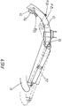
- All of the exemplary embodiments have in common that a seat part support 11, 111, 211 and a backrest support 12, 112, 12 which is adjustable in inclination are movably connected to the frame 10, 110, 210 in a synchronous adjustment movement relative to the frame.
- the backrest support engages under the seat part support.
- the upper part 12b, 112b, 212b of the backrest support 12, 112, 212 is lowered.
- Seat part carrier 11, 111, 211 and backrest carrier 12, 112, 212 are connected to one another by means of a connecting element in such a way that when the transfer movement into the rest position, the backrest carrier in the connection area 12c, 112c, 212c to the seat part carrier is at least slightly more lowered than that at the same time forward and in the rear part 11b, 111b, 211b seat part carriers moved downwards.
- the backrest support and seat support support transmit their movement to one another and to a connecting element by being connected to it at two spaced apart points, so that they can move on two mutually independent tracks.
- the backrest support is guided under an arch under the seat part support, the transfer movement achieved thereby taking place approximately around an imaginary axis M at the level of the user's hip joints.
- the seat part carrier 11, 111, 211 basically moves forward (FIG. 3).
- this movement takes place below a horizontal plane hh, which is determined by the highest point P of the seat part carrier in its working position.
- a guide pin or a guide roller 14, 114 is provided on the frame 10, 110, on which the seat part carrier 11, 111, 211 is guided with an elongated hole guide 11d, 111d.
- this principle can also be reversed, i.e. with an elongated hole guide on the frame, which is inclined forward to avoid raising the front edge of the seat.
- the elongated hole guide 11d slides past the guide roller with a change in inclination.
- the seat part carrier 11 can also be articulated on the frame 10 via at least one pendulum support, each with a joint assigned to the frame and the seat part carrier, which should already be inclined forward in the working position.
- the backrest support 12 merges from an arch arranged at the bottom (guides 12d) into the upper, almost straight part 12b, on which the backrest 25 is articulated on the joint 12f, 112f.
- the backrest support 12 has at its lower end 12a at least one circular-shaped guide 12d which is guided on at least two bearings 13 arranged in a stationary manner on the frame 10.
- the radius of the circular arc enables movement around the imaginary axis.
- the seat part support 11 moves on a path that is independent of the backrest support.
- the seat part support 11 has at its rear end 11b at least one roller 17 which rolls on the track designed as a track 18.
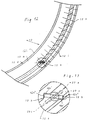
- the schematic FIG. 6 shows the self-centering principle of the symmetrical roller 17, which is guided on an axis 11c of the seat part carrier 11.
- the track 18 provided on the frame 10 has a central recess groove 18a into which the roller is immersed with a central radial rib 17a.
- the roller is designed in the form of a roller, its diameter decreasing linearly outwards, starting from the radial rib 17a, which has the largest diameter of the roller 17.
- the track 18 is wave-shaped (Fig. 4.5). Starting from the position of the roller 17 in the rest position, it is initially convex and then concave when it is transferred to the working position. This initially provides resistance to the chair's initial effort to sag along the arch under load. However, this also leads to an increased relative movement between the seat part support and the backrest support, especially at the start of the transfer movement, which even slips on the shirt of the user.
- the backrest support 12, the seat part support 11 and the frame 10 are connected to one another via a rope or band 19 which is fastened to the backrest support 12 in the region of the curved guides 12d and to the rear edge 10c of the frame 10.
- a rope or band 19 which is fastened to the backrest support 12 in the region of the curved guides 12d and to the rear edge 10c of the frame 10.
- the indirect connection of seat support 11 and backrest support 12 with a band requires that the band is always kept under tension, which is ensured by appropriate training of the track 18 in all positions of the chair.
- a greater or lesser disproportionate pivoting of the backrest support is achieved.
- the belt at least partially wraps around the axis 11c fastened to the seat part carrier 11 clockwise or counterclockwise, which allows a further possibility of fine adjustment of the adjustment possibilities.
- FIGS. 7 and 8 show a further connection with a cable 19 'which is connected to the backrest support 12 at a pivot point 12g via a front section 19b'.
- the rope is connected to the seat part carrier 11 by a rear section 19a ′ at the articulation point 17d of an axis 17c of the guide roller 17.
- the connection to the frame 10 takes place via an axis 15 ′ which is fixed to the frame 10 and carries a roller corresponding to the guide roller 13, at least with regard to its diameter.
- the two parts 19a ', 19b' of the rope 19 ' are connected to this axis.
- the axis 15 ' has an inner section 15a' which lies outside the guide rail of the circular guide 12d of the backrest support and an outer section 15b 'which lies within the circular guide 12d.
- On the inner section 15a ' the part 19a' of the rope 19 'assigned to the seat part carrier 11 is wound up or unwound, while on the outer section 15b' the front part 19b 'of the rope 19' is unwound or unwound at the same time.
- the axis 15 'mounted on the frame 10 has a central bore 15e' which is accessible via radial access openings 15c ', 15d'. This hole allows only one rope to be used to link all three parts. During production, the rope is inserted through one opening 15d 'and exits through the hole 15e' from the other opening 15c '. When making the hole the axis is drilled from one side and then the radial holes are made.
- the axle with its inner section 15a 'is mounted on the frame then the backrest support is attached to the axle sections 15' and the guide roller 13, and the outer section 15b 'is then fastened to the axle by threaded connections. If the axis 15 'also represents a guide roller 13 for the circular-shaped guides 12d of the backrest support 12 (FIG. 7), the backrest support can simultaneously drive the stationary axis and thus move the seat part support.
- the seat part carrier 111 is arranged in the rear part 111b on at least one lever 116 which is articulated on the frame 110 and which is articulated on the joint 111c on the seat part carrier and which is actuated by the backrest carrier 112.
- the backrest support 112 is connected to the seat part support via a connecting element and has at its lower end 112a an actuation profile 115 which engages on a guide 120 of the lever 116.
- the lever which is initially slightly inclined forward is actuated by the lowering backrest support 112, the forward movement of the seat part support being initiated.
- the molded on the backrest support profile presses on the guide designed as a guide roller, so that the two parts roll on each other.
- a separate lowering of the seat part carrier can be achieved, so that the profile e.g. career 18 can be mimicked.
- the backrest support 212 and the seat support 211 are assigned racks 211f, 212e, which mesh with at least one gear 221,222. Either two gears with different sprockets are used, as shown, or the distance between the teeth of the respectively assigned gear and rack is differentiated, so that here too the disproportionate pivoting is realized.
- the seat part carrier 11 can also be guided only at the front end 10b of the frame 10 in two guides which absorb the load on the seat part carrier 11 and which bring about the desired movement independent of the backrest carrier.
- An indirect connection via an elastic spring, preferably a metal tongue, is also possible, which is dimensioned for a sufficient number of load cycles and allows a separate transfer of the seat part carrier.
- the chair can easily be kept in balance in any position, particularly in the case of an embodiment according to the first exemplary embodiment, there is nevertheless the possibility of moving the transfer movement into the rest position against the force of a (compression or tension) spring 24 or a gas spring 24 ' (Fig. 9) perform, which engages the frame 10 and the front end of the seat support 11.
- a (compression or tension) spring 24 or a gas spring 24 ' Fig. 9
- the maximum pivoting angle ⁇ of the backrest support between the rest position and the working position is approximately 2.5 times as large as the angle of inclination ⁇ of the seat part support 11, 111, 211 that occurs.
- recesses 12h spaced apart from one another in the guide direction can be provided in the guides, preferably guide 12d or slot guide 11d of the seat part carrier.
- An adjusting member 27 can be pivoted into these recesses and can be pivoted about an adjusting axis which is arranged transversely to the guide rail and plunges into the latter. The position of the adjusting member 27 changes during the transfer movement relative to the guides, so that a latching in the recesses 12h is possible due to the pivoting movement of the adjusting member.
- the adjustment axis 26 of the adjustment member 27 is mounted on the frame 10 in a stationary manner and the backrest support 12 has the circular-shaped guide 12d with the recesses 12h.
- the adjustment axis 26 extends through either the guide slot already formed by the mounting of the guide rollers 13 or a separate guide slot 12k.
- the recesses can either be arranged on the walls 12 l of the guide 12d or on the base 12m of the guide. In the latter case, the guide reason is also used as a grid adjustment.
- the mutually offset recesses are arranged on both sides of the guide slot at regular intervals and are each at a diagonal distance which corresponds to the length of the adjusting member 27 with its two pivot arms 27a. In the non-operative position, the adjusting member 27 can be arranged approximately parallel to the walls of the guide slot 12k, so that the adjusting member "slides" in the guide slot 12k.
- the pivot arms 27a rest in the locking position on a side surface 27b on a flank 12h of the recesses.
- the actual locking takes place, as can be seen from FIG. 3, by abutting the end faces 27c of the swivel arms 27a on the respective other flank 12h ′′ of the recesses 12h.
- a pivoting movement of approximately 45 ° takes place, the rectangular pivot arms 27a being driven into the triangular recesses 12h.
- the pivoting movement is triggered by a lever 28, which is located under the seat of the chair.
- This lever is under the force of a spring so that it is automatically returned to the locking position. However, it can also be locked out of the active position.
Landscapes
- Health & Medical Sciences (AREA)
- Dentistry (AREA)
- General Health & Medical Sciences (AREA)
- Chairs For Special Purposes, Such As Reclining Chairs (AREA)
- Chairs Characterized By Structure (AREA)
- Chair Legs, Seat Parts, And Backrests (AREA)
- Special Chairs (AREA)
Abstract
Description
Die Erfindung betrifft einen Stuhl, insbesondere einen Bürodrehstuhl nach dem Oberbegriff des Anspruches 1.The invention relates to a chair, in particular an office swivel chair according to the preamble of claim 1.
Aus der DE-OS 39 30 983 ist ein derartiger Stuhl bekannt, bei dem in einer Synchronbewegung der Sitzteilträger nach vorne und im hinteren Teil nach unten bewegt und der Rückenlehneträger dabei geneigt wird. Die Bewegung erfolgt dabei über Synchronhebel , die eine aufwendige Konstruktion erforderlich machen. Rückenlehnenträger und Sitzteilträger sind aber auch über eine Schwenkachse miteinander verbunden, so daß die beiden Teile nicht unabhängig voneinander bewegt werden können. Zwar wird durch die mit mehreren Anlenkpunkten versehenen Synchronhebel die den Hemdauszieheffekt fördernde Relativbewegung zwischen Rückenlehne und Sitzteil bereits weitgehend reduziert, jedoch kann sie aufgrund der Verbindung der beiden Träger nicht ganz beseitigt werden.Such a chair is known from DE-OS 39 30 983, in which the seat part support is moved forward and downward in a synchronous movement and the backrest support is inclined. The movement takes place via synchronous levers, which require a complex construction. Backrest support and seat part support are also connected to one another via a swivel axis, so that the two parts cannot be moved independently of one another. Although the relative movement between the backrest and the seat part, which promotes the shirt pull-out effect, is largely reduced by the synchronizing lever provided with several articulation points, it cannot be completely eliminated due to the connection of the two carriers.
Aus der DE-OS 26 42 091 ist es bekannt, das untere Ende eines Rückenlehnenträgers in einer den Sitz untergreifenden bogenförmigen Führung zu führen. Dabei können die Führungen sowohl als Hülsen als auch als Führungsrollen ausgebildet sein, die in entsprechenden Langlöchern abrollen. Die Bewegung des Rückenlehnenträgers erfolgt um eine imaginäre Achse, die durch die Hüftgelenke des Benutzers gelegt ist. Allerdings kann dadurch, daß der Sitzteilträger nicht nach vorne verschoben werden kann und damit keine Verlagerung des Schwerpunktes des Benutzers erreicht werden kann, nur eine begrenzte Rückenlehnenneigung durchgeführt werden. Ferner ist es bei der Überführung in die Ruhestellung unangenehm, daß der Sitzteilträger sich nicht zumindest in seinem hinteren Teil mit absenkt. Dies fördert den Hemdauszieheffekt, der durch eine dabei auftretende Relativbewegung des Rückenlehnenträgers im Vergleich zum Rücken des Benutzers hervorgerufen wird.From DE-OS 26 42 091 it is known to guide the lower end of a backrest support in an arch-shaped guide engaging under the seat. The guides can be designed both as sleeves and as guide rollers that roll in corresponding elongated holes. The backrest support moves around an imaginary axis that is laid through the user's hip joints. However, due to the fact that the seat part carrier cannot be moved forward and thus no shift in the user's center of gravity can be achieved, only a limited inclination of the backrest can be carried out. Furthermore, when moving to the rest position, it is uncomfortable that the seat part carrier does not lower at least in its rear part. This promotes the shirt pulling effect, which is caused by a Relative movement of the backrest support compared to the back of the user is caused.
Aus der ER-PS 0 303 720 ist ferner ein Stuhl bekannt, bei dem ein L-förmiger Rückenlehnenträger in zwei Führungen aus einer Arbeitsstellung in eine Ruhestellung überführt wird. Dabei bewegt sich das obere Ende des Rückenlehnenträgers nach unten und gleichzeitig wird der mit dem Rückenlehnenträger unmittelbar über eine Schwenkachse verbundene Sitzteilträger nach vorne und im hinteren Teil geringfügig nach unten bewegt. Der Sitzteilträger wird jedoch vorne unerwünscht aufgrund der für die Kippbewegung erforderlichen Anordnung der vorderen Führung des Rückenlehnenträgers angehoben. Der Rückenlehnenträger wird aufgrund seiner L-Form in zwei Führungen gekippt, die dann zwar noch eine Bewegung um eine imaginäre Achse ermöglichen, die jedoch aufgrund des durch die Führungen vorgegebenen großen Radius weitgehend ortsfest in Brust- oder Bauchhöhe in einem kurzen Abstand vor dem Sitzbenutzer liegt. Da aber Rückenlehnenträger und Sitzteilträger über eine gemeinsame Schwenkachse verfügen, ist eine unabhängige Bewegung beider Elemente nicht möglich.From ER-PS 0 303 720 a chair is also known in which an L-shaped backrest support is transferred in two guides from a working position to a rest position. The upper end of the backrest support moves downward and at the same time the seat part support connected to the backrest support directly via a pivot axis is moved forward and slightly downward in the rear part. However, the seat part support is undesirably raised at the front due to the arrangement of the front guide of the backrest support required for the tilting movement. Due to its L-shape, the backrest support is tilted into two guides, which then still allow movement about an imaginary axis, but which due to the large radius specified by the guides is largely stationary at chest or stomach height and a short distance from the seat user . However, since the backrest support and seat support have a common swivel axis, independent movement of both elements is not possible.
Ferner sind Stühle bekannt (EP-OS 36 824; WO 87/06810), bei denen die Bewegung von Sitz und Rückenlehne zueinander um eine imaginäre Achse durch die Hüftgelenke des Benutzers erfolgt. Diese Stühle sind nicht für eine Schwerpunktverschiebung vorgesehen. Zudem ist es schwierig den Rückenlehnenträger im Bogen am Sitzteilträger zu führen, da dies leicht zu einem Durchschlagen des Rückenlehnenträgers führen kann, so daß Verstellmechanismen vorgesehen werden, die keine freie Bewegung des Rückenlehnenträgers zulassen.Chairs are also known (EP-OS 36 824; WO 87/06810), in which the movement of the seat and backrest relative to one another about an imaginary axis takes place through the user's hip joints. These chairs are not intended to shift the center of gravity. In addition, it is difficult to guide the backrest support in the arch on the seat part support, since this can easily lead to the backrest support breaking through, so that adjustment mechanisms are provided which do not permit free movement of the backrest support.
Ausgehend von diesem Stand der Technik liegt der Erfindung die Aufgabe zugrunde, einen Stuhl der eingangs genannten Gattung derart weiterzubilden, daß auf kostengünstige Weise ein ästhetisch anspruchsvoller Stuhl verwirklicht wird, der die Überführung in eine möglichst bequeme Ruhestellung erlaubt.Based on this prior art, the invention has for its object to develop a chair of the type mentioned in such a way that an aesthetically sophisticated chair is realized in a cost-effective manner, which allows the transfer to a comfortable rest position as possible.
Diese Aufgabe wird durch die Merkmale des Anspruchs 1 gelöst.This object is solved by the features of claim 1.
Grundsätzlich bestimmt sich die dabei geforderte Bequemlichkeit eines Stuhls danach, wie weit die Rückenlehne nach hinten geneigt werden kann. Als komfortbestimmender Faktor kann die Relation Rückenlehnen/Sitzflächen-Andruck bei induzierten Lastwechseln während des "dynamischen Sitzens" gelten. Bei einem Bürostuhl wird diese maximal mögliche Neigung grundsätzlich durch die erlaubte Ausladung der Rückenlehne begrenzt, da bei einer Neigung der Rückenlehne ohne gleichzeitige Verschiebung des Sitzteilträgers nach vorne der Schwerpunkt so weit von der Drehachse wegbewegt wird, daß eine erhöhte Kippgefahr besteht. Weiter ist es erwünscht, daß der Stuhl sich bei der Neigung der Rückenlehne gleichzeitig mit seinem hinteren Teil des Sitzteilträgers nach unten bewegt, um keine den Hemdauszieheffekt fördernde Relativbewegung zwischen Sitzteil und Rückenlehne zu erhalten. Grundsätzlich wäre eine solche Bewegung ohne weiteres möglich, wenn man Rückenlehne und Sitzteilträger gemeinsam auf einer Kreisbahn bewegt. Dadurch würde sich aber in unerwünschter Weise der vordere Teil des Sitzteils mit der Auflagezone der vorderen Oberschenkel anheben, was zum Anschwellen der Beine sowie zu Mißempfindungen wie "Einschlafen" und "Kribbeln" führen kann.Basically, the required comfort of a chair is determined by how far the backrest can be tilted backwards. The relation of backrest / seat pressure in case of induced load changes during "dynamic sitting" can be considered a comfort-determining factor. In the case of an office chair, this maximum possible inclination is fundamentally limited by the permissible projection of the backrest, since if the backrest is inclined without simultaneously moving the seat part carrier forward, the center of gravity is moved so far away from the axis of rotation that there is an increased risk of tipping. Furthermore, it is desirable that the chair moves downward simultaneously with its rear part of the seat part carrier when the backrest is inclined, in order not to obtain a relative movement between the seat part and the backrest which promotes the pulling out of the shirt. In principle, such a movement would be readily possible if the backrest and seat part carrier are moved together on a circular path. However, this would undesirably raise the front part of the seat part with the support zone of the front thighs, which can lead to swelling of the legs and to sensations such as "falling asleep" and "tingling".
Erfindungsgemäß wird nun der Schwerpunkt bei einer Verstellung der Rückenlehnenneigung durch die Vorwärtsbewegung des Sitzteilträgers so nach vorne verschoben, daß auch größere Neigungen gefahrlos verwirklicht werden können, ohne daß zur Abstützung am Fuß des Stuhles weit auskragende Ausleger erforderlich sind. Der Sitzteilträger wird unabhängig vom Rückenlehnenträger bewegt, so daß das unerwünschte Anheben der Auflagezone der Oberschenkel vermieden wird. Vielmehr werden dadurch die Voraussetzungen für eine ergonomischen Prinzipien folgende, nahezu in gleicher Höhe bleibende Horizontalbewegung der Vorderkante der Sitzfläche geschaffen.According to the invention, the center of gravity is now shifted forward when the backrest inclination is adjusted by the forward movement of the seat part carrier, so that even greater inclinations can be realized safely without the need for cantilevered outriggers for support at the foot of the chair. The seat part carrier is moved independently of the backrest carrier, so that the undesired lifting of the support zone of the thighs is avoided. Rather, the prerequisites for an ergonomic principle following horizontal movement of the front edge of the seat, which remains at almost the same height, are created.
Der Hemdauszieheffekt, der dazu führt, daß einem Sitzbenutzer das Hemd ausgezogen wird, wenn er das Rückenlehnenteil körpermotorisch nach hinten neigt und sich dabei mit seinem Rücken an der Rückenlehne anlehnt, beruht auf einer Relativbewegung zwischen Rückenlehne und dem Rücken des Benutzers, bei der sich üblicherweise die Rückenlehne relativ zum Rücken des Benutzers nach oben bewegt. Demgegenüber wird nun nicht nur diese Relativbewegung auf Null herabgesetzt, sondern vielmehr darüberhinaus der Rückenlehnenträger im Vergleich zum Sitzteilträger verstärkt abgesenkt, so daß im Gegensatz zu bekannten Stühlen nun der Rückenlehnenträger sich relativ zum Rücken des Benutzers nach unten bewegt, ihm also das Hemd angezogen wird.The shirt pull-out effect, which causes a seat user to take off his shirt when he tilts the backrest part backwards with the aid of a body motor and thereby leans with his back against the backrest, is based on a relative movement between the backrest and the back of the user, in which usually the backrest moves upward relative to the user's back. In contrast, will now not only reduced this relative movement to zero, but rather also lowered the backrest support more than the seat part support, so that, in contrast to known chairs, the backrest support now moves downwards relative to the back of the user, i.e. the shirt is put on him.
Somit ergibt sich ein bequemes Sitzmöbel mit den Möglichkeiten einer Überführung in eine zurückgelehnte Stellung. In jeder Zwischen- oder Endposition des durch die Führung von Rückenlehnenträger und Sitzteilträger auf verschiedenen Bahnen weich geführten Gleitvorgangs der Sitzschale wird die aktive Möglichkeit einer gewichtsverlagernden Sitzhaltungsänderung, des sogenannte "dynamischen Sitzens", geboten. Weitreichende Bewegungsfreiräume mit extremer Sitz-(Liege-) Neigung der Körperstamm-Achse (Wirbelsäule) verbunden mit sicherer und andruckminimierter Abstützung des Körpergewichts durch großflächige Kontaktzonen der anatomisch durchgeformten Sitzschale gewähren eine maximale Relaxierung der Bauch- und Zwerchfellmuskulatur mit positiver Wirkung auf die erreichbare Atemtiefe und Herzförderleistung. Entspannungs- und kreislaufbedingt kommt es zu einer gesundheitsförderlichen, spürbaren Steigerung des Sitzkomforts. Dabei wird der Sitzteilträger auf einer gesonderten Bahn unabhängig von der kreisförmigen Bewegung des Rückenlehnenträgers bewegt. Dem bei kreisbogenförmigen Führungen des Rückenlehnenträgers auftretendem Durchsacken des Rückenlehnenträgers bei Belastung kann begegnet werden, so daß außer der körpermotorischen Bewegung der Benutzerperson kaum noch Hilfsmittel zur Überführung in die beiden Endstellungen erforderlich sind.This results in comfortable seating with the possibility of being transferred to a reclined position. In every intermediate or end position of the sliding process of the seat shell, which is guided smoothly by guiding the backrest support and seat part support on different tracks, the active possibility of a weight-shifting change in posture, the so-called "dynamic sitting", is offered. Extensive freedom of movement with extreme sitting (lying) inclination of the trunk axis (spine) combined with safe and pressure-minimized support of the body weight through large contact zones of the anatomically shaped seat shell allow maximum relaxation of the abdominal and diaphragm muscles with a positive effect on the achievable depth of breath and Cardiac output. As a result of relaxation and circulation, there is a noticeable increase in seating comfort that promotes health. The seat part carrier is moved on a separate path regardless of the circular movement of the backrest carrier. The sagging of the backrest support occurring under circular guides of the backrest support can be counteracted, so that apart from the body movement of the user hardly any aids are required for transferring to the two end positions.
Bei einer Ausbildung nach Anspruch 2 sind bei bogenförmiger Führung des Rückenlehnenträgers dem Gleitvorgang überlagerte, stetige Bewegungsabläufe um eine (gegenüber dem Benutzer unveränderliche) Achse möglich, wobei durch kontinuierliche Lastwechsel in den Kontaktzonen (Gesäß/Rücken) auch neue Bewegungsfreiräume erschlossen und der Sitzkomfort des Benutzers gesteigert werden. Unter einer Führung entlang eines Bogens ist dabei eine Führung zu verstehen, die entweder am Rückenlehnenträger bogenförmige Elemente besitzt, die an stationären Lagern des Gestells entlangbewegt werden, oder die am Rückenlehnenträger Lager besitzt, die in bogenförmigen Führungen des Gestells bewegt werden, ohne daß es darauf ankommt, ob es sich bei dem Bogen um einen Kreisbogen oder den Abschnitt einer Hyperbel, Parabel oder um einen ähnlich gebogenen Abschnitt einer geometrischen Linie handelt.In an embodiment according to claim 2, the sliding process superimposed on the sliding process, continuous movement sequences about an (invariable to the user) axis are possible with continuous load changes in the contact zones (buttocks / back) also open up new freedom of movement and the seating comfort of the user with arcuate guidance of the backrest support be increased. A guide along an arch is to be understood to mean a guide that either has arch-shaped elements on the backrest support that are moved along stationary bearings of the frame, or that on Backrest support has bearings that are moved in arcuate guides of the frame, regardless of whether the arc is a circular arc or the section of a hyperbola, parabola or a similarly curved section of a geometric line.
Wird nach Anspruch 3 die Achse, um die sich zumindest der Rückenlehnenträger bewegt, in Höhe der imaginären Achse zwischen beiden Hüftgelenken des Benutzers angeordnet, so wird eine Relativbewegung zwischen Mensch und Stuhl verringert.If, according to
Bei einer Ausbildung nach den Ansprüchen 6 und 7 kann mit einer Rolle eine dauerhafte Führung auf einer Laufbahn dadurch bewerkstelligt werden, daß diese Rolle reibungsverringernd nur auf kleinen Punkten entlang ihres Umfangs abrollt. Gerät die Rolle aus ihrer zentrierten Lage heraus, so führt der nach außen abnehmende Durchmesser zu einer Selbstzentrierung, da der bei einer seitlichen Bewegung anstehende größere Durchmesser bestrebt ist, sich ähnlich wie Rollen auf entsprechend geformten Eisenbahnschienen zurückstellen. Wird die Laufbahn entsprechend ausgebildet, wird bei der anfänglichen Überführungsbewegung aus der Arbeitsstellung heraus eine verstärkte Relativbewegung zwischen Sitzteilträger und Rückenlehnenträger hervorgerufen.In an embodiment according to claims 6 and 7, a roller can be used for permanent guidance on a career in that this roller rolls along its circumference to reduce friction only at small points. If the roller moves out of its centered position, the outwardly decreasing diameter leads to self-centering, since the larger diameter that occurs during a lateral movement tends to reset itself like rollers on appropriately shaped railroad tracks. If the track is designed accordingly, an increased relative movement between the seat part carrier and the backrest carrier is produced during the initial transfer movement from the working position.
Bei einer Ausbildung nach Anspruch 8 ist als Verbindungsmittel zwischen Rückenlehnenträger und Sitzteilträger ein Band oder Seil vorgesehen, das zudem mit dem Gestell verbunden ist. Im Zusammenspiel mit der Laufbahn kann dadurch eine optimale Überführungsbewegung verwirklicht werden und dennoch das Band in jeder Stellung gespannt gehalten werden.In an embodiment according to claim 8, a band or rope is provided as a connecting means between the backrest support and the seat part support, which is also connected to the frame. In combination with the running track, an optimal transfer movement can be achieved and the belt can still be held in any position.
Bei einer Ausbildung nach den Ansprüchen 9 und 10 wird am stationären Punkt des Gestelles eine Achse vorgesehen, die durch entsprechende Formgebung die gewünschten Relativbewegungen zwischen Rückenlehnenträger und Sitzteilträger beeinflussen und koordinieren kann. Als Verbindungselement können aufwickelbare Bänder, Seile oder dergleichen verwendet werden. Vorzugsweise wird - aufgrund der Dehnungscharakteristik - ein Seil bei Überführungsbewegung am einen Teil der Achse aufgewickelt und am anderen Teil der Achse abgewickelt. Selbstverständlich können jedoch auch zwei Seile und auch zwei verschiedene Achsen eingesetzt werden.In an embodiment according to
Eine besondere Koordinierungsmöglichkeit ergibt sich, wenn die Achse in zwei Abschnitte aufgeteilt ist, die unterschiedliche Durchmesser aufweisen. Da der Rückenlehnenträger sich bei der Überführungsbewegung relativ stärker bewegen muß als der gleichzeitig bewegte Sitzteilträger, wird an dem dem Rückenlehnenträger zugeordneten Abschnitt der Achse ein größerer Durchmesser vorgesehen, wodurch auch die erforderlichen Wicklungen des Seiles für den Rückenlehnenträger auf engerem Raum angeordnet werden können. Die Achse dient zugleich als Führungsrolle für den Sitzteilträger, wodurch der Antrieb der Achse sichergestellt ist. Nach Anspruch 11 kann ein einziges Seil verwendet werden, das konstruktiv einfach in der Achse durch eine zentrische Bohrung mit radialen Zugangsöffnungen auf der einen Seite der Bohrung hineingeschoben wird und auf der anderen Seite der Bohrung wieder austritt.A special coordination possibility arises when the axis is divided into two sections that have different diameters. Since the backrest support has to move relatively more strongly during the transfer movement than the seat part support which is moving at the same time, a larger diameter is provided on the section of the axle assigned to the backrest support, as a result of which the required windings of the cable for the backrest support can also be arranged in a narrower space. The axle also serves as a guide roller for the seat support, which ensures the drive of the axle. According to
Allen Ausführungsformen ist gemeinsam, daß aufgrund der wenigen erforderlichen Mittel die gesamte Stuhlmechanik mit geringem Aufwand so verkleidet werden kann, daß sie auch höchsten ästhetischen Ansprüchen genügt, da ohne weiteres eine schlanke Stuhl-Silhouette erreicht werden kann.All embodiments have in common that due to the few means required, the entire chair mechanism can be covered with little effort so that it also meets the highest aesthetic standards, since a slim chair silhouette can be achieved without further ado.
Im folgenden wird die Erfindung anhand der Zeichnungen an mehreren Ausführungsbeispielen näher erläutert.The invention is explained in more detail below with reference to the drawings in several exemplary embodiments.
Es zeigen:
- Fig. 1:
- Den in Arbeitsstellung befindlichen Stuhl in Seitenansicht in einer ersten schematisch dargestellten Ausführungsform,
- Fig. 2:
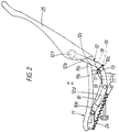
- den Stuhl gemäß Fig. 1 in Ruhestellung,
- Fig. 3:
- eine Abbildung gemäß Fig. 1 und 2 wobei der Stuhl in Ruhestellung gestrichelt dargestellt über den Stuhl in Arbeitsstellung gezeichnet ist,
- Fig.4,5:
- eine vergrößerte, schematische Darstellung des Betätigungsmechanismus' in Arbeitsstellung bzw. Ruhestellung,
- Fig. 6:
- eine schematische Darstellung von Rolle und geschnittener Laufbahn in einer Seitenansicht gemäß Fig. 5,
- Fig. 7:
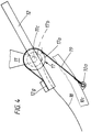
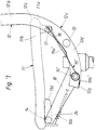
- einen vergößerten Ausschnitt in einer Fig. 1 entsprechenden Darstellung mit einem weiteren Verbindungsmittel,
- Fig. 8:
- eine Aufsicht auf die linke Hälfte des Stuhles in einer schematischen Darstellung, wobei zur Klarheit der obere Teil der kreisbogenförmigen Führung des Rückenlehnenträgers entfernt ist.
- Fig. 9:
- eine vergrößerte Abbildung des unteren Abschnittes von Fig. 3,
- Fig. 10:
- den Stuhl gemäß Fig. 1 in einer weiteren Ausführungsform,
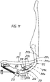
- Fig. 11:
- den Stuhl gemäß Fig. 1 in einer dritten Ausführungsform.
- Fig. 12;
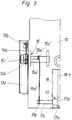
- einen vergrößerten Ausschnitt einer Führungsschiene,
- Fig. 13
- einen vergrößerten Ausschnitt der Führungsschiene aus Fig. 2 mit darin befindlichem Verstellglied,
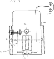
- Fig. 14
- eine Aufsicht auf den am Gestell angeordneten Verstellmechanismus
- Fig. 1:
- The chair in the working position in a side view in a first schematically illustrated embodiment,
- Fig. 2:
- 1 in the rest position,
- Fig. 3:
- 1 and 2, wherein the chair is shown in dashed lines in the rest position over the chair in the working position,
- Fig. 4,5:
- an enlarged, schematic representation of the actuating mechanism in the working position or rest position,
- Fig. 6:
- 3 shows a schematic illustration of the roller and the cut career in a side view according to FIG. 5,
- Fig. 7:
- 2 shows an enlarged detail in a representation corresponding to FIG. 1 with a further connecting means,
- Fig. 8:
- a plan view of the left half of the chair in a schematic representation, the upper part of the circular-arc guide of the backrest support is removed for clarity.
- Fig. 9:
- 3 shows an enlarged illustration of the lower section of FIG. 3,
- Fig. 10:
- 1 in a further embodiment,
- Fig. 11:
- 1 in a third embodiment.
- Fig. 12;
- an enlarged section of a guide rail,
- Fig. 13
- 3 shows an enlarged section of the guide rail from FIG. 2 with the adjusting element located therein,
- Fig. 14
- a top view of the adjustment mechanism arranged on the frame
Die Abbildungen zeigen den Stuhl, der vorzugsweise als Bürodrehstuhl eingesetzt wird in drei Ausführungsbeispielen. Zur Unterscheidung der Bezugszeichen der einzelnen Ausführungsbeispiele sind die Bezugszeichen des zweiten und dritten Ausführungsbeispiels vom ersten Ausführungsbeispiel dadurch unterschieden, daß bei einander entsprechenden Teilen hinsichtlich der Bezugszeichen vorne eine 1 bzw. 2 vorangesetzt ist, sie also um 100 bzw. 200 gegenüber dem ersten Ausführungsbeispiel erhöht sind.The pictures show the chair, which is preferably used as an office swivel chair in three exemplary embodiments. To differentiate the reference numerals of the individual exemplary embodiments, the reference numerals of the second and third exemplary embodiments are distinguished from the first exemplary embodiment in that, in the case of corresponding parts, a 1 is given in front with respect to the reference numerals or 2 is set in advance, ie they are increased by 100 or 200 compared to the first embodiment.
Allen Ausführungsbeispielen ist gemeinsam, daß ein Sitzteilträger 11,111,211 und ein in der Neigung verstellbarer Rückenlehnenträger 12,112,212 beweglich mit dem Gestell 10,110,210 zu einer synchronen gegenüber dem Gestell erfolgenden Verstellbewegung verbunden sind. An seinem unteren Ende 12a,112a,212a untergreift der Rückenlehnenträger den Sitzteilträger. Bei einer durch die Körpermotorik des Benutzers eingeleiteten Überführungsbewegung aus einer aufrechten Arbeitsstellung in eine Ruhestellung wird der obere Teil 12b,112b,212b des Rückenlehnenträgers 12,112,212 abgesenkt. Sitzteilträger 11,111,211 und Rückenlehnenträger 12,112,212 sind mittels eines Verbindungselementes so miteinander verbunden, daß bei der Überführungsbewegung in die Ruhestellung der Rückenlehnenträger im Anschlußbereich 12c,112c,212c an den Sitzteilträger wenigstens geringfügig stärker abgesenkt wird als der gleichzeitig nach vorn und im hinteren Teil 11b,111b,211b nach unten bewegte Sitzteilträger. Rückenlehnenträger und Sitzteilträger übertragen Ihre Bewegung aufeinander und auf ein Verbindungselement, indem sie an zwei voneinander beabstandeten Punkten damit verbunden sind, so daß sie sich auf zwei voneinander unabhängigen Bahnen bewegen können.All of the exemplary embodiments have in common that a
Bei der Überführungsbewegung wird der Rückenlehnenträger unter dem Sitzteilträger entlang eines Bogens geführt, wobei die dabei erzielte Überführungsbewegung etwa um eine imaginäre Achse M in Höhe der Hüftgelenke des Benutzers erfolgt.During the transfer movement, the backrest support is guided under an arch under the seat part support, the transfer movement achieved thereby taking place approximately around an imaginary axis M at the level of the user's hip joints.
Bei der Überführungsbewegung bewegt sich der Sitzteilträger 11,111,211 grundsätzlich nach vorne (Fig. 3). Durch die Anordnung der Führungselemente für den Sitzteilträger erfolgt diese Bewegung unterhalb einer horizontalen Ebene h-h, die durch den höchsten Punkt P des Sitzteilträgers in seiner Arbeitsstellung bestimmt ist. Für die vordere Führung des Sitzteilträgers ist am Gestell 10,110 ein Führungszapfen oder eine Führungsrolle 14,114 vorgesehen, an der der Sitzteilträger 11,111,211 mit einer Langlochführung 11d,111d geführt ist. Natürlich kann dieses Prinzip auch umgekehrt werden, also mit einer Langlochführung am Gestell, die jedoch zur Vermeidung der Anhebung der vorderen Sitzkante nach vorne geneigt ist. Bei den Ausführungsbeispielen gleitet hingegen die Langlochführung 11d unter Neigungsänderung an der Führungsrolle vorbei. Alternativ kann aber auch der Sitzteilträger 11 am Gestell 10 über wenigstens eine Pendelstütze mit je einem dem Gestell und dem Sitzteilträger zugeordneten Gelenk angelenkt werden, wobei diese in Arbeitsstellung bereits nach vorne geneigt sein sollte. Der Rückenlehnenträger 12 geht in der Seitenansicht ausgehend von einem unten angeordneten Bogen (Führungen 12d) in den oberen, nahezu gerade ausgebildeten Teil 12b über, an dem die Rückenlehne 25 an dem Gelenk 12f,112f angelenkt ist.During the transfer movement, the
Wie aus den Figuren 1 bis 3 ersichtlich, besitzt der Rückenlehnenträger 12 an seinem unteren Ende 12a wenigstens eine kreisbogenförmige Führung 12d , die auf wenigstens zwei am Gestell 10 stationär angeordneten Lagern 13 geführt ist. Der Radius des Kreisbogens ermöglicht die Bewegung um die angesprochene imaginäre Achse. Es ist aber auch möglich, den Rückenlehnenträger 12 an seinem unteren Ende 12a mit einer kreisbogenförmigen Führungshülse zu versehen, die ein stationär am Gestell 10 wenigstens an einem Punkt befestigtes Horn umgreift, das den gleichen Radius wie die Führungshülsen aufweist.As can be seen from FIGS. 1 to 3, the
Der Sitzteilträger 11 bewegt sich bei der mit dem Rückenlehnenträger 12 erfolgenden Überführungsbewegung auf einer vom Rückenlehnenträger unabhängigen Bahn. Dazu besitzt der Sitzteilträger 11 an seinem hinteren Ende 11b wenigstens eine Rolle 17, die auf der als Laufbahn 18 ausgebildeten Bahn abrollt. Anhand der schematischen Figur 6 läßt sich dabei das selbstzentrierende Prinzip der symmetrischen, auf einer Achse 11c des Sitzteilträgers 11 geführten Rolle 17 erkennen. Zu diesem Zweck weist die am Gestell 10 vorgesehene Laufbahn 18 eine mittige Vertiefungsrille 18a auf, in die die Rolle mit einer mittigen Radialrippe 17a eintaucht. Die Rolle ist walzenförmig ausgebildet, wobei ihr Durchmesser nach außen, ausgehend von der Radialrippe 17a, die den größten Durchmesser der Rolle 17 aufweist, sich linear verringert. Dadurch rollt nur ein geringer Teil der Walze auf der Laufbahn ab und die Rolle wird von selbst aus einer außermittigen Lage wieder in ihre zentriert Lage geführt, da der nach außen abnehmende Durchmesser der walzenförmigen Rolle die Rolle dazu zwingt, sich aufgrund des bei einer seitlichen Bewegung auf der einen Seite anstehenden größeren Durchmessers selbst zurückstellen.During the transfer movement taking place with the
Die Laufbahn 18 ist wellenförmig ausgebildet (Fig. 4,5). Ausgehend von der Stellung der Rolle 17 in der Ruhestellung ist sie bei Überführung in die Arbeitsstellung zunächst konvex und dann konkav gewölbt. Dadurch wird dem anfänglichen Bestreben des Stuhles, unter Last entlang dem Bogen durchzusacken, zunächst ein Widerstand entgegengebracht. Dies führt aber auch zu einer verstärkten Relativbewegung zwischen Sitzteilträger und Rückenlehnenträger gerade bei Beginn der Überführungsbewegung, die dem Benutzer garadezu das Hemd überstreift.The
Wie aus den Figuren 4 bis 6 zu entnehmen, sind Rückenlehnenträger 12, Sitzteilträger 11 und Gestell 10 über ein Seil oder Band 19 miteinander verbunden , das am Rückenlehnenträger 12 im Bereich der bogenförmigen Führungen 12d und am hinteren Rand 10c des Gestells 10 befestigt ist. Als Alternative für eine Verbindung der drei miteinander in Wirkverbindung stehenden Elemente Sitzteilträger 11, Rückenlehnenträger 12 und Gestell 10 besteht die Möglichkeit, ein vorzugsweise seil- oder bandförmiges Verbindungselement einzusetzen, das an zwei dieser drei Teile befestigt ist und mit dem dritten Teil beweglich verbunden ist.As can be seen from FIGS. 4 to 6, the
Die mittelbare Verbindung von Sitzteilträger 11 und Rückenlehnenträger 12 mit einem Band erfordert, daß das Band stets unter Spannung gehalten wird, was durch eine entsprechende Ausbildung der Laufbahn 18 in allen Stellungen des Stuhles gewährleistet wird. Je nach Angriffspunkt des Bandes am Außen- oder Innenradius des Bogens wird eine stärkere oder geringere überproportionale Verschwenkung des Rückenlehnenträgers erreicht. Das Band umschlingt die am Sitzteilträger 11 befestigte Achse 11c wenigstens teilweise im oder gegen den Uhrzeigersinn, was eine weitere Möglichkeit einer Feinjustierung der Verstellmöglichkeiten erlaubt.The indirect connection of
Figuren 7 und 8 zeigen eine weitere Verbindung mit einem Seil 19', das über einen vorderen Abschnitt 19b' mit dem Rückenlehnenträger 12 an einem Anlenkpunkt 12g verbunden ist. Mit einem hinteren Abschnitt 19a' steht das Seil am Anlenkpunkt 17d einer Achse 17c der Führungsrolle 17 mit dem Sitzteilträger 11 in Verbindung.FIGS. 7 and 8 show a further connection with a cable 19 'which is connected to the
Die Verbindung zum Gestell 10 erfolgt über eine am Gestell 10 stationär befestigte Achse 15', die eine der Führungsrolle 13 zumindest hinsichtlich ihres Durchmessers entsprechende Rolle trägt. Die beiden Teile 19a',19b' des Seiles 19' sind mit dieser Achse verbunden. Die Achse 15' weist einen inneren Abschnitt 15a' auf, der außerhalb der Führungsschiene der kreisbogenförmigen Führung 12d des Rückenlehnenträgers liegt und einen äußeren Abschnitt 15b', der innerhalb der kreisbogenförmigen Führung 12d liegt. Auf dem inneren Abschnitt 15a' wird der dem Sitzteilträger 11 zugeordnete Teil 19a' des Seiles 19' auf- bzw. abgewickelt, während auf dem äußeren Abschnitt 15b' der vordere Teil 19b' des Seiles 19' zugleich ab- bzw. aufgewickelt wird.The connection to the
Bei Überführungsbewegung in die Ruhestellung wird der hintere Teil 19a' des Seiles aufgewickelt und der vordere Teil 19b' des Seiles 19' abgewickelt, da in diesem Fall die Führungsrolle 17, die den Sitzteilträger auf einer Laufbahn 18 führt, näher an die stationäre Achse 15 herantritt. Der äußere Abschnitt 15b der Achse 15 besitzt einen größeren Durchmesser als der innere Abschnitt 15a. Dadurch kann eine Koordinierung der Relativbewegung zwischen Rückenlehnenträger und Sitzteilträger erfolgen und die Seilabschnitte werden stets unter Zug gehalten.When moving to the rest position, the
Die am Gestell 10 gelagerte Achse 15' besitzt eine zentrische Bohrung 15e', die über radiale Zugangsöffnungen 15c',15d' zugänglich ist. Diese Bohrung ermöglicht die Verwendung lediglich eines Seils für die Anlenkung aller drei Teile. Das Seil wird bei der Produktion durch die eine Öffnung 15d' eingeführt und tritt durch die Bohrung 15e' aus der anderen Öffnung 15c' wieder aus. Bei Herstellung der Bohrung wird die Achse von einer Seite angebohrt und dann werden die radialen Bohrungen vorgenommen. Beim Zusammenbau des Stuhles wird die Achse mit ihrem inneren Abschnitt 15a' am Gestell gelagert, dann wird der Rückenlehnenträger auf die vortretenden Achsenabschnitte der Achse 15' als auch der Führungsrolle 13 aufgesteckt und durch Gewindeverbindungen wird dann der äußere Abschnitt 15b' an der Achse befestigt. Wenn die Achse 15' zugleich auch eine Führungsrolle 13 für die kreisbogenförmigen Führungen 12d des Rückenlehnenträgers 12 darstellt (Fig. 7), kann der Rückenlehnenträger zugleich die stationäre Achse antreiben und damit den Sitzteilträger bewegen.The axis 15 'mounted on the
Beim zweiten in Figur 10 dargestellten Ausführungsbeispiel ist der Sitzteilträger 111 im hinteren Teil 111b auf wenigstens einem am Gestell 110 angelenkten Hebel 116 angeordnet ist, der am Gelenk 111c am Sitzteilträger angelenkt ist und der vom Rückenlehnenträger 112 betätigt ist. Der Rückenlehnenträger 112 ist über ein Verbindungselement mit dem Sitzteilträger verbunden und besitzt an seinem unteren Ende 112a ein Betätigungsprofil 115, das an einer Führung 120 des Hebels 116 angreift. Bei der Überführungsbewegung wird der zu Beginn geringfügig nach vorne geneigte Hebel durch den sich absenkenden Rückenlehnenträger 112 betätigt, wobei die Vorwärtsbewegung des Sitzteilträgers eingeleitet wird. Das am Rückenlehnenträger angeformte Betätigungsprofil drückt dabei auf die als Führungsrolle ausgebildete Führung, so daß die beiden Teile aufeinander abrollen. Je nach Ausbildung des Profils kann damit eine gesonderte Absenkung des Sitzteilträger verwirklicht werden, so daß mit dem Profil z.B. die Laufbahn 18 nachgeahmt werden kann.In the second exemplary embodiment shown in FIG. 10, the
Eine solche Nachahmung der Laufbahn 18 ist aber auch z.B. mit einer Ausbildung nach dem in Figur 11 dargestellten dritten Ausführungsbeispiel möglich. Hier sind dem Rückenlehnenträger 212 und dem Sitzteilträger 211 Zahnstangen 211f,212e zugeordnet, die mit wenigstens einem Zahnrad 221,222 kämmen. Entweder werden dabei, wie dargestellt zwei Zahnräder mit unterschiedlichem Zahnkranz eingesetzt oder der Abstand der Zähne von jeweils zugeordnetem Zahnrad und Zahnstange wird unterschieden, so daß auch hier die überproportionale Verschwenkung realisiert wird.Such an imitation of the
In zeichnerisch nicht dargestellter Weise kann der Sitzteilträger 11 auch nur am vorderen Ende 10b des Gestells 10 in zwei die Belastung des Sitzteilträgers 11 aufnehmenden Führungen geführt sein, die die gewünschte vom Rückenlehnenträger unabhängige Bewegung bewirken. In diesem Fall muß dann nur noch durch ein beliebiges Hilfsmittel, wie z.B. das Band 19 die mittelbare Verbindung zwischen Sitzteilträger und Rückenlehnenträger hergestellt werden. Auch ist eine mittelbare Verbindung über eine elastische Feder, vorzugsweise eine Metallzunge möglich, die für eine ausreichende Anzahl von Lastspielen bemessen ist und eine gesonderte Überführung des Sitzteilträgers erlaubt.In a manner not shown in the drawing, the
Zwar läßt sich der Stuhl insbesondere bei einer Ausbildung nach dem ersten Ausführungbeispiel leicht in jeder Lage im Gleichgewicht halten, jedoch besteht dennoch die Möglichkeit, die Überführungsbewegung in die Ruhestellung entgegen der Kraft einer (Druck- oder Zug-) Feder 24 oder einer Gasfeder 24' (Fig. 9) durchzuführen, die am Gestell 10 und am vorderen Ende des Sitzteilträgers 11 angreift.Although the chair can easily be kept in balance in any position, particularly in the case of an embodiment according to the first exemplary embodiment, there is nevertheless the possibility of moving the transfer movement into the rest position against the force of a (compression or tension)
Allen Ausführungsbeispielen ist gemeinsam, daß der maximale Verschwenkwinkel α des Rückenlehnenträgers zwischen Ruhestellung und Arbeitsstellung etwa 2,5 mal so groß ist wie der dabei auftretende Neigungswinkel β des Sitzteilträgers 11,111,211. Um eine Festlegung des Stuhles in jeder gewünschten Position zu ermöglichen, können in den Führungen, vorzugsweise Führung 12d oder Langlochführung 11d des Sitzteilträgers in Führungsrichtung voneinander beabstandete Ausnehmungen 12h vorgesehen werden. In diese Ausnehmungen ist ein Verstellglied 27 einschwenkbar, das um eine quer zur Führungschiene angeordnete und in diese eintauchende Verstellachse verschwenkbar ist. Die Lage des Verstellgliedes 27 ändert sich bei der Überführungsbewegung gegenüber den Führungen, so daß durch die Schwenkbewegung des Verstellgliedes eine Rastung in den Ausnehmungen 12h möglich ist.All of the exemplary embodiments have in common that the maximum pivoting angle α of the backrest support between the rest position and the working position is approximately 2.5 times as large as the angle of inclination β of the
Die Verstellachse 26 des Verstellgliedes 27 ist am Gestell 10 stationär gelagert und der Rückenlehnenträger 12 besitzt die kreisbogenförmige Führung 12d mit den Ausnehmungen 12h. Die Verstellachse 26 durchgreift dabei entweder den bereits durch die Lagerung der Führungsrollen 13 gebildeten Führungsschlitz oder einen gesonderten Führungsschlitz 12k. Die Ausnehmungen können dabei entweder an den Wandungen 12 l der Führung 12d angeordnet sein oder am Grund 12m der Führung. In letzerem Fall wird somit der Führungsgrund zugleich als Rasterverstellung verwendet. In jedem Fall sind die gegeneinander versetzten Ausnehmungen auf beiden Seiten des Führungsschlitzes in regelmäßigen Abständen angeordnet und befinden sich jeweils in einem diagonalen Abstand, der der Länge des Verstellgliedes 27 mit seinen beiden Schwenkarmen 27a entspricht. Außer Wirkstellung kann das Verstellglied 27 ungefähr parallel zu den Wandungen des Führungsschlitzes 12k angeordnet werden, so daß ein "Gleiten" des Verstellgliedes im Führungsschlitz 12k stattfindet.The
Die Schwenkarme 27a liegen in Verriegelungsstellung an einer Seitenfläche 27b an einer Flanke 12h der Ausnehmungen an. Das eigentliche Verriegeln findet, wie aus Fig. 3 ersichtlich, durch das Anstoßen der Stirnflächen 27c der Schwenkarme 27a an der jeweils anderen Flanke 12h'' der Ausnehmungen 12h statt. Bei der Verschwenkung erfolgt eine Schwenkbewegung von ungefähr 45°, wobei die rechteckförmigen Schwenkarme 27a in die dreieckförmigen Ausnehmungen 12h eingesteuert werden.The pivot arms 27a rest in the locking position on a side surface 27b on a
Wie aus Fig. 14 ersichtlich, wird die Schwenkbewegung über einen Hebel 28 ausgelöst, der sich unter der Sitzfläche des Stuhles befindet. Dieser Hebel steht unter der Kraft einer Feder, so daß er automatisch in Verriegelungsstellung zurückgeführt wird. Er kann jedoch auch außer Wirkstellung verrastet werden.As can be seen from Fig. 14, the pivoting movement is triggered by a
- 10,110,21010,110,210
- Gestellframe
- 10a10a
- Anlenkpunkt von 19Articulation point from 19th
- 10b,110b10b, 110b
- vorderes Endefront end
- 10c,110c,210c10c, 110c, 210c
- hinterer Randrear edge
- 11,111,21111,111,211
- SitzteilträgerSeat part carrier
- 11a,111a,211a11a, 111a, 211a
- Anschlußbereich an 12Connection area at 12
- 11b,111b11b, 111b
- hinterer Teilback part
- 11c11c
- Achse für 17Axis for 17th
- 111c111c
- Anlenkung für 116Articulation for 116
- 11d11d
- LanglochführungSlot guide
- 111e111e
- Anlenkung für 112Linkage for 112
- 211f211f
- ZahnstangeRack
- 12,112,21212,112,212
- RückenlehnenträgerBackrest support
- 12a,112a,212a12a, 112a, 212a
- unteres Endelower end
- 12b,112b12b, 112b
- oberes Teilupper part
- 12c,112c,212c12c, 112c, 212c
- Anschlußbereich an 11Connection area at 11
- 12d12d
- kreisbogenförmige Führungcircular arc-shaped guide
- 212e212e
- Zahnstange von 212Rack of 212
- 12f,112f12f, 112f
- Anlenkpunkt RückenlehneArticulation point backrest
- 12g12g
- Anlenkpunkt von 19Articulation point from 19th
- 12h12h
- AusnehmungenRecesses
- 12h', 12h''12h ', 12h' '
- FlankenFlanks
- 12k12k
- FührungsschlitzGuide slot
- 12l12l
- WandungWall
- 12m12m
- Bodenground
- 13,21313.213
- Lagerwarehouse
- 14,11414.114
- vordere Führungsrolle von 11,111front guide roller of 11.111
- 15'15 '
- Achseaxis
- 15a'15a '
- innerer Abschnittinner section
- 15b'15b '
- äußerer Abschnittouter section
- 15c',15d'15c ', 15d'
- ZugangsöffnungenAccess openings
- 15e'15e '
- Bohrungdrilling
- 1717th
- Rollerole
- 17a17a
- RadialrippeRadial rib
- 17b17b
- AußenbereichOutdoor area
- 17d17d
- Anlenkpunkt für 19Articulation point for 19th
- 1818th
- Laufbahncareer
- 18a18a
- VertiefungsrilleDeepening groove
- 19, 19'19, 19 '
- Band oder SeilTape or rope
- 19a'19a '
- hinterer Teilback part
- 19b'19b '
- vorderer Teilfront part
- 24,24'24.24 '
- Federfeather
- 2525th
- Rückenlehnebackrest
- 2626
- VerstellachseAdjustment axis
- 2727
- VerstellgliedActuator
- 27a27a
- SchwenkarmSwivel arm
- 27b27b
- SeitenflächeSide surface
- 27c27c
- StirnflächeFace
- 2828
- Hebellever
- 115115
- BetätigungsprofilActuation profile
- 116116
- Hebellever
- 120120
- Führungguide
- 221,222221.222
- ZahnräderGears
- MM
- Achse durch die Hüftgelenke des BenutzersAxis through the user's hip joints
- h-hh-h
- horizontale Ebenehorizontal plane
- PP
- höchster Punkt von 11 in Arbeitsstellunghighest point of 11 in working position
- αα
- Verschwenkwinkel von 12Swivel angle of 12
- ββ
- Neigungswinkel von 11Inclination angle of 11
Claims (14)
daß am Gestell (10) wenigstens ein Führungszapfen vorgesehen ist, an der der Sitzteilträger (11) mit einer Langlochführung (11d) geführt ist.Chair according to one of the preceding claims, characterized in
that at least one guide pin is provided on the frame (10), on which the seat part carrier (11) is guided with an elongated hole guide (11d).
Applications Claiming Priority (4)
| Application Number | Priority Date | Filing Date | Title |
|---|---|---|---|
| DE4135948A DE4135948C2 (en) | 1991-10-31 | 1991-10-31 | Chair, in particular office swivel chair |
| DE4135948 | 1991-10-31 | ||
| DE4208227A DE4208227A1 (en) | 1991-10-31 | 1992-03-14 | CHAIR, ESPECIALLY OFFICE SWIVEL CHAIR |
| DE4208227 | 1992-03-14 |
Publications (2)
| Publication Number | Publication Date |
|---|---|
| EP0539733A1 true EP0539733A1 (en) | 1993-05-05 |
| EP0539733B1 EP0539733B1 (en) | 1995-12-06 |
Family
ID=25908700
Family Applications (1)
| Application Number | Title | Priority Date | Filing Date |
|---|---|---|---|
| EP92116447A Expired - Lifetime EP0539733B1 (en) | 1991-10-31 | 1992-09-25 | Chair, in particular rotatable office chair |
Country Status (13)
| Country | Link |
|---|---|
| US (1) | US5354120A (en) |
| EP (1) | EP0539733B1 (en) |
| JP (1) | JPH05211927A (en) |
| CN (1) | CN1074361A (en) |
| AT (1) | ATE131017T1 (en) |
| CA (1) | CA2079644A1 (en) |
| CZ (1) | CZ321692A3 (en) |
| DE (3) | DE4135948C2 (en) |
| HU (1) | HUT63040A (en) |
| LT (1) | LT3458B (en) |
| PL (1) | PL296407A1 (en) |
| SK (1) | SK321692A3 (en) |
| ZA (1) | ZA927678B (en) |
Cited By (8)
| Publication number | Priority date | Publication date | Assignee | Title |
|---|---|---|---|---|
| EP0614633A1 (en) * | 1993-02-25 | 1994-09-14 | Herman Miller, Inc. | Adjustbale backrest for a chair |
| WO1996001581A3 (en) * | 1994-07-08 | 1996-06-06 | Rolf Voelkle | Seat |
| WO1997022282A1 (en) * | 1995-12-18 | 1997-06-26 | Peter Opsvik A.S | An adjusting device for chairs |
| US5797653A (en) * | 1993-07-22 | 1998-08-25 | Dauphin Entwicklungs - U. Beteiligungs-Gmbh | Chair, in particular office chair |
| DE19502485C2 (en) * | 1995-01-27 | 1999-09-16 | Fus Rainer | chair |
| US5971481A (en) * | 1996-10-11 | 1999-10-26 | Giroflex Entwicklungs Ag | Chair, specially an office chair |
| WO2002067726A1 (en) * | 2001-02-28 | 2002-09-06 | Interstuhl Büromöbel GmbH & Co. KG | Chair, especially an office chair |
| EP2896326A1 (en) * | 2014-01-21 | 2015-07-22 | Stoll Giroflex AG | Seating furniture, in particular a chair |
Families Citing this family (98)
| Publication number | Priority date | Publication date | Assignee | Title |
|---|---|---|---|---|
| BR9306555A (en) | 1992-06-15 | 1998-09-15 | Miller Herman Inc | Office chair |
| US5765914A (en) * | 1995-06-07 | 1998-06-16 | Herman Miller, Inc. | Chair with a tilt control mechanism |
| US5810439A (en) * | 1996-05-09 | 1998-09-22 | Haworth, Inc. | Forward-rearward tilt control for chair |
| US6086153A (en) | 1997-10-24 | 2000-07-11 | Steelcase Inc. | Chair with reclineable back and adjustable energy mechanism |
| US6250715B1 (en) | 1998-01-21 | 2001-06-26 | Herman Miller, Inc. | Chair |
| ITVI980182A1 (en) * | 1998-09-25 | 2000-03-25 | Enrico Cioncada | VARIABLE TRIM CHAIR. |
| DE29910620U1 (en) * | 1999-06-17 | 2000-10-19 | König + Neurath AG, 61184 Karben | Chair, especially office chair |
| USD445580S1 (en) | 2000-09-28 | 2001-07-31 | Formway Furniture Limited | Chair |
| USD446397S1 (en) | 2000-09-28 | 2001-08-14 | Formway Furniture Limited | Chair |
| USD460300S1 (en) | 2000-09-28 | 2002-07-16 | Formway Furniture Limited | Slotted seat panel for a chair |
| AU783829B2 (en) | 2000-09-28 | 2005-12-08 | Formway Furniture Limited | A reclinable chair |
| USD448219S1 (en) | 2000-09-28 | 2001-09-25 | Formway Furniture Limited | Castored base for a chair |
| USD448277S1 (en) | 2000-09-28 | 2001-09-25 | Formway Furniture Limited | Castor |
| USD463144S1 (en) | 2000-09-28 | 2002-09-24 | Formway Furniture Limited | Chair |
| AUPR054400A0 (en) | 2000-09-29 | 2000-10-26 | Formway Furniture Limited | A castor |
| DE10152560A1 (en) | 2000-10-12 | 2003-05-08 | Sven Poppel | Office chair with adjustable seat and backrest has vertically spaced shaped elements at rear of backrest coupled to pivot lever operated by setting device |
| DE10122946C1 (en) * | 2001-05-11 | 2003-01-30 | Armin Sander | Chair, especially office chair |
| DE10122948C1 (en) * | 2001-05-11 | 2003-03-13 | Armin Sander | Chair, especially office chair |
| DE10126001A1 (en) * | 2001-05-18 | 2002-11-21 | Bock 1 Gmbh & Co | Preloaded spring arrangement, in particular for spring loading of synchronous mechanisms in office chairs |
| DE10125994A1 (en) * | 2001-05-18 | 2002-11-21 | Bock 1 Gmbh & Co | Synchronous mechanism for a correlated movement of the seat backrest of an office chair |
| US6585320B2 (en) | 2001-06-15 | 2003-07-01 | Virco Mgmt. Corporation | Tilt control mechanism for a tilt back chair |
| US6644741B2 (en) | 2001-09-20 | 2003-11-11 | Haworth, Inc. | Chair |
| DE20116683U1 (en) * | 2001-10-13 | 2002-01-24 | Völkle, Rolf, 72290 Loßburg | Seating, in particular office swivel chair |
| US20030132653A1 (en) * | 2001-10-18 | 2003-07-17 | Doug Thole | Tension control mechanism for a chair |
| KR100434997B1 (en) * | 2002-01-02 | 2004-06-09 | 주식회사 일룸 | the back of a chair |
| ES2192476B2 (en) * | 2002-01-18 | 2004-06-01 | Sebastian Aramburu Echevarria | RECLINING ARMCHAIR. |
| NZ518944A (en) | 2002-05-14 | 2004-09-24 | Formway Furniture Ltd | Height adjustable arm for chair with outer stem releasably lockable to inner stem by engagement of recesses |
| KR100474392B1 (en) * | 2002-12-03 | 2005-03-10 | 주식회사 일룸 | a tilting chair |
| DE20306014U1 (en) * | 2003-04-14 | 2003-06-26 | Vitra Patente Ag, Muttenz | Mechanism for a chair with a gas spring for synchronous control of the inclination of the seat and backrest |
| DE10318759B3 (en) * | 2003-04-25 | 2004-07-29 | Armin Sander | Office chair with pivoted backrest support and synchronous mechanism for adjustment of seat position simultaneous with adjustment of backrest |
| US7322653B2 (en) * | 2003-06-13 | 2008-01-29 | Vlad Dragusin | Integrated videogaming and computer workstation |
| US7207629B2 (en) * | 2003-06-23 | 2007-04-24 | Herman Miller, Inc. | Tilt chair |
| US6945602B2 (en) * | 2003-12-18 | 2005-09-20 | Haworth, Inc. | Tilt control mechanism for chair |
| US6969116B2 (en) * | 2003-12-30 | 2005-11-29 | Hni Technologies Inc. | Chair with backward and forward passive tilt capabilities |
| DE602005025169D1 (en) | 2004-05-13 | 2011-01-13 | Humanscale Corp | Chair with columnar foot with membrane plates |
| US7237841B2 (en) | 2004-06-10 | 2007-07-03 | Steelcase Development Corporation | Back construction with flexible lumbar |
| US7458637B2 (en) | 2004-06-10 | 2008-12-02 | Steelcase Inc. | Back construction with flexible lumbar |
| HK1064859A2 (en) * | 2004-06-21 | 2005-01-14 | 田雨阳 | Synchronous coordinate system of back of chair |
| KR100499792B1 (en) * | 2004-10-13 | 2005-07-07 | 이규윤 | Chair |
| USD623449S1 (en) | 2005-05-13 | 2010-09-14 | Humanscale Corporation | Mesh backrest for a chair |
| AR057387A1 (en) * | 2005-06-20 | 2007-12-05 | Humanscale Corp | SEAT APPLIANCE WITH RECLINING MOVEMENT |
| US20070222266A1 (en) * | 2006-03-21 | 2007-09-27 | Ditto Sales, Inc. | Nestable and stackable chair |
| USD661135S1 (en) | 2006-06-20 | 2012-06-05 | Humanscale Corporation | Pair of armrests for a chair or the like |
| DE502007000434D1 (en) * | 2006-10-06 | 2009-03-26 | Stoll Giroflex Ag | Synchronized office chair |
| BRPI0823267A2 (en) | 2007-01-29 | 2013-09-24 | Miller Herman Inc | seat structure and methods for using it |
| KR100968540B1 (en) | 2008-03-27 | 2010-07-08 | 듀오백코리아 주식회사 | Sliding tilting device of the chair |
| KR100968547B1 (en) | 2008-03-27 | 2010-07-08 | 듀오백코리아 주식회사 | Tilting device of chair |
| CN104188409B (en) | 2008-05-26 | 2017-07-07 | 斯特尔凯斯公司 | For the adaptability backrest of seat unit |
| KR20110022040A (en) * | 2008-06-05 | 2011-03-04 | 가부시기가이샤 우찌다요우고우 | Chair with tiltable back |
| DE102009009287A1 (en) * | 2009-02-17 | 2010-09-09 | Uhlenbrock, Christel | Seating furniture, in particular office swivel chair |
| US8100478B2 (en) * | 2009-07-06 | 2012-01-24 | Honda Motor Co., Ltd. | Vehicle seat assembly |
| MY159810A (en) * | 2009-08-18 | 2017-02-15 | Integrated Furniture Tech Ltd | Adjustable furniture |
| EP2608699B1 (en) * | 2010-08-25 | 2015-11-25 | L&P Property Management Company | Tilt mechanism for a chair and chair |
| PL2608700T3 (en) | 2010-08-25 | 2014-12-31 | L&P Property Man Co | Tilt mechanism for a chair and chair |
| JP5634890B2 (en) * | 2011-01-17 | 2014-12-03 | カリモク家具株式会社 | Chair |
| US8556345B2 (en) * | 2011-03-14 | 2013-10-15 | Sheng Jia Sheng Co., Ltd. | Chair having angle and tension adjusting functions |
| JP2012249826A (en) * | 2011-06-03 | 2012-12-20 | Takano Co Ltd | Chair |
| WO2013017279A1 (en) * | 2011-08-03 | 2013-02-07 | Haworth, Inc. | Adjusting mechanism for setting a restoring force which acts on a backrest of a chair, and office chair having an adjusting mechanism of this type |
| CN104203050A (en) | 2011-09-21 | 2014-12-10 | 赫尔曼米勒有限公司 | Double layer headrest, body support structure and method of supporting a user's skull |
| DE112012004365T5 (en) * | 2011-10-21 | 2014-07-03 | Jae Hyun Lee | Corrective chair with lubricant |
| KR101300678B1 (en) | 2011-12-08 | 2013-08-27 | 한국생산기술연구원 | Gliding type Tilting apparatus for chair and having it |
| CN103355974B (en) * | 2012-04-09 | 2016-04-13 | 周新 | The inclination type chair frame that backrest can lock when using state |
| US9504326B1 (en) | 2012-04-10 | 2016-11-29 | Humanscale Corporation | Reclining chair |
| EP2892390B1 (en) * | 2012-09-05 | 2017-06-07 | Godrej & Boyce Mfg Co Ltd | Chair with adjustable backrest and seat |
| US9706845B2 (en) | 2012-09-20 | 2017-07-18 | Steelcase Inc. | Chair assembly |
| USD696545S1 (en) | 2013-07-30 | 2013-12-31 | Steelcase, Inc. | Rear surface of a chair back |
| US9801471B2 (en) | 2014-04-17 | 2017-10-31 | Hni Technologies Inc. | Chair and chair control assemblies, systems, and methods |
| CN203952966U (en) * | 2014-06-26 | 2014-11-26 | 陈国巨 | The chair that when chair back layback, cushion reach also declines simultaneously |
| EP3193716B1 (en) | 2014-09-15 | 2024-05-01 | Attenti Electronic Monitoring Ltd. | Impairment detection with biological considerations |
| US11324421B2 (en) | 2014-09-15 | 2022-05-10 | 3M Innovative Properties Company | Impairment detection with environmental considerations |
| ES2988518T3 (en) | 2014-09-15 | 2024-11-20 | Attenti Electronic Monitoring Ltd | Detection of deficiencies |
| DE102015102007B3 (en) * | 2015-02-12 | 2016-07-28 | Wilkhahn Wilkening + Hahne Gmbh + Co. | seating |
| US10966527B2 (en) | 2017-06-09 | 2021-04-06 | Steelcase Inc. | Seating arrangement and method of construction |
| US11259637B2 (en) | 2015-04-13 | 2022-03-01 | Steelcase Inc. | Seating arrangement |
| US10194750B2 (en) | 2015-04-13 | 2019-02-05 | Steelcase Inc. | Seating arrangement |
| MY206922A (en) | 2015-04-13 | 2025-01-17 | Steelcase Inc | Seating arrangement |
| EP3108867B1 (en) * | 2015-06-23 | 2018-12-05 | Cefla Societa' Cooperativa | Dental patient chair |
| CA3195904A1 (en) * | 2016-02-05 | 2017-08-10 | Formway Furniture Limited | A chair and components |
| CN106108444B (en) * | 2016-08-23 | 2023-11-07 | 浙江博泰家具有限公司 | Frame structure for reclining chair |
| US10231546B2 (en) | 2017-03-02 | 2019-03-19 | Knoll, Inc. | Chair back tilt mechanism |
| CN109484259B (en) * | 2018-09-26 | 2020-08-25 | 盐城同环机电科技有限公司 | Vehicle seat back locking device |
| USD937024S1 (en) | 2020-02-19 | 2021-11-30 | Steelcase Inc. | Backrest |
| USD961317S1 (en) | 2020-02-19 | 2022-08-23 | Steelcase Inc. | Backrest |
| USD937595S1 (en) | 2020-02-19 | 2021-12-07 | Steelcase Inc. | Chair |
| USD961281S1 (en) | 2020-02-19 | 2022-08-23 | Steelcase Inc. | Chair |
| USD936985S1 (en) | 2020-02-19 | 2021-11-30 | Steelcase Inc. | Chair |
| USD961280S1 (en) | 2020-02-19 | 2022-08-23 | Steelcase Inc. | Chair |
| USD936984S1 (en) | 2020-02-19 | 2021-11-30 | Steelcase Inc. | Chair |
| USD935824S1 (en) | 2020-02-19 | 2021-11-16 | Steelcase Inc. | Seat |
| DE102020110707A1 (en) | 2020-04-20 | 2021-10-21 | Bock 1 Gmbh & Co. Kg | Seating |
| US11690455B2 (en) * | 2020-09-18 | 2023-07-04 | Dinkar Chellaram | Synchronous-tilt reclining chair |
| USD995179S1 (en) | 2021-01-20 | 2023-08-15 | Steelcase Inc. | Chair with lumbar support |
| USD988048S1 (en) | 2021-01-20 | 2023-06-06 | Steelcase Inc. | Lumbar support |
| USD988049S1 (en) | 2021-05-12 | 2023-06-06 | Steelcase Inc. | Lumbar support |
| USD995180S1 (en) | 2021-05-12 | 2023-08-15 | Steelcase Inc. | Chair with lumbar support |
| CN113729428B (en) * | 2021-05-27 | 2025-06-27 | 广东联友办公家具有限公司 | An electronically controlled chassis and seat |
| CN113729426B (en) * | 2021-05-27 | 2025-11-28 | 广东联友办公家具有限公司 | Seat chassis and seat |
| US12414884B1 (en) * | 2021-06-04 | 2025-09-16 | Ki Mobility, LLC | Tiltable wheelchair |
Citations (5)
| Publication number | Priority date | Publication date | Assignee | Title |
|---|---|---|---|---|
| US3036862A (en) * | 1959-01-31 | 1962-05-29 | Stuttgarter Karosseriewerk Reu | Adjusting device for a folding back for a vehicle seat |
| DE2642091A1 (en) * | 1976-09-18 | 1978-03-23 | Wilde & Spieth | Office chair with adaptable backrest - has esp. disposed swivel axis ensuring automatic adjustment to all body movements |
| DE3530868A1 (en) * | 1985-08-29 | 1987-03-05 | Kusch Co Sitzmoebel | Rocking mechanism for chairs |
| FR2627968A1 (en) * | 1988-03-07 | 1989-09-08 | Eurosit | Office chair with back moved backwards and forwards - with back joined to support articulated on seat support and cable connecting back and seat support |
| DE3930983A1 (en) * | 1989-09-16 | 1991-03-28 | Rolf Voelkle | SEAT FURNITURE WITH TILT ADJUSTABLE SEAT |
Family Cites Families (5)
| Publication number | Priority date | Publication date | Assignee | Title |
|---|---|---|---|---|
| DE2735583A1 (en) * | 1977-08-06 | 1979-02-15 | Wilde & Spieth | Office chair with adjustable seat and backrest - has lever-operated bolt engaging in toothed segments on frame |
| DE7815561U1 (en) * | 1978-05-24 | 1978-09-14 | Martin Stoll Giroflex Gmbh, 7897 Tiengen | |
| FR2478982A1 (en) * | 1980-03-26 | 1981-10-02 | Faure Bertrand | IMPROVEMENTS ON SEATS WITH ADJUSTABLE RECLINING BACKREST |
| NO160896C (en) * | 1986-05-09 | 1989-06-14 | Jurek Buchacz | ADJUSTABLE SEATING DEVICE. |
| ES2021653B3 (en) | 1987-08-14 | 1991-11-16 | Grammer Ag | SEAT, ESPECIALLY WORK SEAT, OR SEAT, OFFICE CHAIR OR DRIVER'S SEAT |
-
1991
- 1991-10-31 DE DE4135948A patent/DE4135948C2/en not_active Expired - Fee Related
-
1992
- 1992-03-14 DE DE4208227A patent/DE4208227A1/en not_active Withdrawn
- 1992-09-25 AT AT92116447T patent/ATE131017T1/en not_active IP Right Cessation
- 1992-09-25 EP EP92116447A patent/EP0539733B1/en not_active Expired - Lifetime
- 1992-09-25 DE DE59204595T patent/DE59204595D1/en not_active Expired - Fee Related
- 1992-10-01 CA CA002079644A patent/CA2079644A1/en not_active Abandoned
- 1992-10-06 ZA ZA927678A patent/ZA927678B/en unknown
- 1992-10-15 SK SK321692A patent/SK321692A3/en unknown
- 1992-10-19 LT LTIP218A patent/LT3458B/en not_active IP Right Cessation
- 1992-10-21 US US07/964,025 patent/US5354120A/en not_active Expired - Fee Related
- 1992-10-23 CZ CS923216A patent/CZ321692A3/en unknown
- 1992-10-26 CN CN92112423A patent/CN1074361A/en active Pending
- 1992-10-26 HU HU9203352A patent/HUT63040A/en unknown
- 1992-10-29 PL PL29640792A patent/PL296407A1/en unknown
- 1992-11-02 JP JP4317770A patent/JPH05211927A/en not_active Withdrawn
Patent Citations (5)
| Publication number | Priority date | Publication date | Assignee | Title |
|---|---|---|---|---|
| US3036862A (en) * | 1959-01-31 | 1962-05-29 | Stuttgarter Karosseriewerk Reu | Adjusting device for a folding back for a vehicle seat |
| DE2642091A1 (en) * | 1976-09-18 | 1978-03-23 | Wilde & Spieth | Office chair with adaptable backrest - has esp. disposed swivel axis ensuring automatic adjustment to all body movements |
| DE3530868A1 (en) * | 1985-08-29 | 1987-03-05 | Kusch Co Sitzmoebel | Rocking mechanism for chairs |
| FR2627968A1 (en) * | 1988-03-07 | 1989-09-08 | Eurosit | Office chair with back moved backwards and forwards - with back joined to support articulated on seat support and cable connecting back and seat support |
| DE3930983A1 (en) * | 1989-09-16 | 1991-03-28 | Rolf Voelkle | SEAT FURNITURE WITH TILT ADJUSTABLE SEAT |
Cited By (11)
| Publication number | Priority date | Publication date | Assignee | Title |
|---|---|---|---|---|
| EP0614633A1 (en) * | 1993-02-25 | 1994-09-14 | Herman Miller, Inc. | Adjustbale backrest for a chair |
| US5511852A (en) * | 1993-02-25 | 1996-04-30 | Herman Miller, Inc. | Adjustable backrest for a chair |
| US5797653A (en) * | 1993-07-22 | 1998-08-25 | Dauphin Entwicklungs - U. Beteiligungs-Gmbh | Chair, in particular office chair |
| WO1996001581A3 (en) * | 1994-07-08 | 1996-06-06 | Rolf Voelkle | Seat |
| DE19502485C2 (en) * | 1995-01-27 | 1999-09-16 | Fus Rainer | chair |
| WO1997022282A1 (en) * | 1995-12-18 | 1997-06-26 | Peter Opsvik A.S | An adjusting device for chairs |
| US6095606A (en) * | 1995-12-18 | 2000-08-01 | Peter Opsvik As | Adjusting device for chairs |
| US5971481A (en) * | 1996-10-11 | 1999-10-26 | Giroflex Entwicklungs Ag | Chair, specially an office chair |
| WO2002067726A1 (en) * | 2001-02-28 | 2002-09-06 | Interstuhl Büromöbel GmbH & Co. KG | Chair, especially an office chair |
| EP2896326A1 (en) * | 2014-01-21 | 2015-07-22 | Stoll Giroflex AG | Seating furniture, in particular a chair |
| WO2015109413A1 (en) * | 2014-01-21 | 2015-07-30 | Stoll Giroflex Ag | Seating furniture, in particular a chair |
Also Published As
| Publication number | Publication date |
|---|---|
| DE59204595D1 (en) | 1996-01-18 |
| US5354120A (en) | 1994-10-11 |
| LTIP218A (en) | 1994-10-25 |
| ZA927678B (en) | 1993-04-15 |
| CZ321692A3 (en) | 1993-05-12 |
| CN1074361A (en) | 1993-07-21 |
| DE4208227A1 (en) | 1993-09-16 |
| HU9203352D0 (en) | 1993-04-28 |
| JPH05211927A (en) | 1993-08-24 |
| CA2079644A1 (en) | 1993-05-01 |
| HUT63040A (en) | 1993-07-28 |
| DE4135948C2 (en) | 1993-12-23 |
| LT3458B (en) | 1995-10-25 |
| SK321692A3 (en) | 1993-10-06 |
| PL296407A1 (en) | 1993-06-28 |
| EP0539733B1 (en) | 1995-12-06 |
| ATE131017T1 (en) | 1995-12-15 |
| DE4135948A1 (en) | 1993-05-06 |
Similar Documents
| Publication | Publication Date | Title |
|---|---|---|
| EP0539733B1 (en) | Chair, in particular rotatable office chair | |
| DE3930983C2 (en) | Seating with an adjustable seat | |
| EP0296578B1 (en) | Seat for an office chair or the like, with seat and backrest adjustable by shifting body weight | |
| DE60300064T2 (en) | Chair with movable seat and backrest | |
| EP0265782B1 (en) | Sitting furniture | |
| DE4405653C2 (en) | Vehicle seat | |
| EP2095741B1 (en) | Office chair | |
| CH666171A5 (en) | CHAIR WITH REAR TILTABLE SEAT AND BACKREST CARRIER. | |
| DE2717331A1 (en) | CHAIR WITH ADJUSTABLE BACKREST | |
| DE2908897A1 (en) | ARMCHAIR WITH ADJUSTABLE BACKREST | |
| DE3103188A1 (en) | Adjustable reclining chair | |
| DE3844102A1 (en) | SEAT FOR AN OFFICE CHAIR OD. DGL. | |
| DE2153417B2 (en) | Adjustable chair | |
| DE2141022B2 (en) | Dental patient chair with reclining backrest and adjustable seat | |
| DE102007024218A1 (en) | Seating furniture e.g. armchair, has head element adjustable as whole in height relative to seat part, where head element is adjustable by guide along carrier for head element, and guide runs curvedly in adjustment direction of head element | |
| DE8511034U1 (en) | Seating furniture in the form of a chair or armchair, in particular for office purposes | |
| DE69508135T2 (en) | Relaxation chair | |
| EP0419714B1 (en) | Backrest with a lumbosacral support adjustable in height | |
| DE8419826U1 (en) | Adjustable chair | |
| DE102011051966B4 (en) | chair | |
| DE2638924C3 (en) | Work table with movable chair | |
| DE102006033049B4 (en) | Chair, especially office chair | |
| DE3301352C2 (en) | Upholstered armchair with adjustable seat and back upholstery | |
| DE9214798U1 (en) | Upholstered furniture | |
| EP0085134B1 (en) | Sitting and lying furniture with a plurality of upholstered parts |
Legal Events
| Date | Code | Title | Description |
|---|---|---|---|
| PUAI | Public reference made under article 153(3) epc to a published international application that has entered the european phase |
Free format text: ORIGINAL CODE: 0009012 |
|
| AK | Designated contracting states |
Kind code of ref document: A1 Designated state(s): AT BE CH DE ES FR GB IE IT LI NL SE |
|
| 17P | Request for examination filed |
Effective date: 19930420 |
|
| 17Q | First examination report despatched |
Effective date: 19941108 |
|
| GRAA | (expected) grant |
Free format text: ORIGINAL CODE: 0009210 |
|
| AK | Designated contracting states |
Kind code of ref document: B1 Designated state(s): AT BE CH DE ES FR GB IE IT LI NL SE |
|
| PG25 | Lapsed in a contracting state [announced via postgrant information from national office to epo] |
Ref country code: IT Free format text: LAPSE BECAUSE OF FAILURE TO SUBMIT A TRANSLATION OF THE DESCRIPTION OR TO PAY THE FEE WITHIN THE PRESCRIBED TIME-LIMIT;WARNING: LAPSES OF ITALIAN PATENTS WITH EFFECTIVE DATE BEFORE 2007 MAY HAVE OCCURRED AT ANY TIME BEFORE 2007. THE CORRECT EFFECTIVE DATE MAY BE DIFFERENT FROM THE ONE RECORDED. Effective date: 19951206 Ref country code: ES Free format text: THE PATENT HAS BEEN ANNULLED BY A DECISION OF A NATIONAL AUTHORITY Effective date: 19951206 |
|
| REF | Corresponds to: |
Ref document number: 131017 Country of ref document: AT Date of ref document: 19951215 Kind code of ref document: T |
|
| REG | Reference to a national code |
Ref country code: IE Ref legal event code: FG4D Free format text: 66422 |
|
| REF | Corresponds to: |
Ref document number: 59204595 Country of ref document: DE Date of ref document: 19960118 |
|
| REG | Reference to a national code |
Ref country code: CH Ref legal event code: NV Representative=s name: PATENTANWALTSBUREAU BOSSHARD UND LUCHS |
|
| PG25 | Lapsed in a contracting state [announced via postgrant information from national office to epo] |
Ref country code: SE Effective date: 19960306 |
|
| GBT | Gb: translation of ep patent filed (gb section 77(6)(a)/1977) |
Effective date: 19960221 |
|
| ET | Fr: translation filed | ||
| PG25 | Lapsed in a contracting state [announced via postgrant information from national office to epo] |
Ref country code: IE Free format text: LAPSE BECAUSE OF NON-PAYMENT OF DUE FEES Effective date: 19960627 |
|
| REG | Reference to a national code |
Ref country code: IE Ref legal event code: FD4D Ref document number: 66422 Country of ref document: IE |
|
| PLBE | No opposition filed within time limit |
Free format text: ORIGINAL CODE: 0009261 |
|
| 26N | No opposition filed | ||
| PGFP | Annual fee paid to national office [announced via postgrant information from national office to epo] |
Ref country code: GB Payment date: 20010903 Year of fee payment: 10 |
|
| PGFP | Annual fee paid to national office [announced via postgrant information from national office to epo] |
Ref country code: FR Payment date: 20010917 Year of fee payment: 10 |
|
| PGFP | Annual fee paid to national office [announced via postgrant information from national office to epo] |
Ref country code: NL Payment date: 20010920 Year of fee payment: 10 |
|
| PGFP | Annual fee paid to national office [announced via postgrant information from national office to epo] |
Ref country code: AT Payment date: 20010921 Year of fee payment: 10 Ref country code: BE Payment date: 20010921 Year of fee payment: 10 Ref country code: CH Payment date: 20010921 Year of fee payment: 10 |
|
| REG | Reference to a national code |
Ref country code: GB Ref legal event code: IF02 |
|
| PGFP | Annual fee paid to national office [announced via postgrant information from national office to epo] |
Ref country code: DE Payment date: 20020820 Year of fee payment: 11 |
|
| PG25 | Lapsed in a contracting state [announced via postgrant information from national office to epo] |
Ref country code: GB Free format text: LAPSE BECAUSE OF NON-PAYMENT OF DUE FEES Effective date: 20020925 Ref country code: AT Free format text: LAPSE BECAUSE OF NON-PAYMENT OF DUE FEES Effective date: 20020925 |
|
| PG25 | Lapsed in a contracting state [announced via postgrant information from national office to epo] |
Ref country code: CH Free format text: LAPSE BECAUSE OF NON-PAYMENT OF DUE FEES Effective date: 20020930 Ref country code: LI Free format text: LAPSE BECAUSE OF NON-PAYMENT OF DUE FEES Effective date: 20020930 Ref country code: BE Free format text: LAPSE BECAUSE OF NON-PAYMENT OF DUE FEES Effective date: 20020930 |
|
| BERE | Be: lapsed |
Owner name: *VOLKLE ROLF Effective date: 20020930 |
|
| PG25 | Lapsed in a contracting state [announced via postgrant information from national office to epo] |
Ref country code: NL Free format text: LAPSE BECAUSE OF NON-PAYMENT OF DUE FEES Effective date: 20030401 |
|
| GBPC | Gb: european patent ceased through non-payment of renewal fee |
Effective date: 20020925 |
|
| REG | Reference to a national code |
Ref country code: CH Ref legal event code: PL |
|
| PG25 | Lapsed in a contracting state [announced via postgrant information from national office to epo] |
Ref country code: FR Free format text: LAPSE BECAUSE OF NON-PAYMENT OF DUE FEES Effective date: 20030603 |
|
| REG | Reference to a national code |
Ref country code: FR Ref legal event code: ST |
|
| PG25 | Lapsed in a contracting state [announced via postgrant information from national office to epo] |
Ref country code: DE Free format text: LAPSE BECAUSE OF NON-PAYMENT OF DUE FEES Effective date: 20040401 |