EP0538794A1 - Combinaison souris d'ordinateur et microphone et méthode d'utilisation - Google Patents
Combinaison souris d'ordinateur et microphone et méthode d'utilisation Download PDFInfo
- Publication number
- EP0538794A1 EP0538794A1 EP92117927A EP92117927A EP0538794A1 EP 0538794 A1 EP0538794 A1 EP 0538794A1 EP 92117927 A EP92117927 A EP 92117927A EP 92117927 A EP92117927 A EP 92117927A EP 0538794 A1 EP0538794 A1 EP 0538794A1
- Authority
- EP
- European Patent Office
- Prior art keywords
- computer
- switch
- electrical
- mouse
- audio data
- Prior art date
- Legal status (The legal status is an assumption and is not a legal conclusion. Google has not performed a legal analysis and makes no representation as to the accuracy of the status listed.)
- Withdrawn
Links
Images
Classifications
-
- G—PHYSICS
- G06—COMPUTING; CALCULATING OR COUNTING
- G06F—ELECTRIC DIGITAL DATA PROCESSING
- G06F3/00—Input arrangements for transferring data to be processed into a form capable of being handled by the computer; Output arrangements for transferring data from processing unit to output unit, e.g. interface arrangements
- G06F3/01—Input arrangements or combined input and output arrangements for interaction between user and computer
- G06F3/03—Arrangements for converting the position or the displacement of a member into a coded form
- G06F3/033—Pointing devices displaced or positioned by the user, e.g. mice, trackballs, pens or joysticks; Accessories therefor
- G06F3/0354—Pointing devices displaced or positioned by the user, e.g. mice, trackballs, pens or joysticks; Accessories therefor with detection of 2D relative movements between the device, or an operating part thereof, and a plane or surface, e.g. 2D mice, trackballs, pens or pucks
- G06F3/03543—Mice or pucks
-
- G—PHYSICS
- G06—COMPUTING; CALCULATING OR COUNTING
- G06F—ELECTRIC DIGITAL DATA PROCESSING
- G06F3/00—Input arrangements for transferring data to be processed into a form capable of being handled by the computer; Output arrangements for transferring data from processing unit to output unit, e.g. interface arrangements
- G06F3/16—Sound input; Sound output
- G06F3/167—Audio in a user interface, e.g. using voice commands for navigating, audio feedback
Definitions
- the present invention relates generally to a computer mouse, and more particularly, to a mouse that includes a cursor movement control device, a microphone, and control switches within a single housing to permit audio input into a computer via a mouse.
- Some computers available today permit a user to store an audio message in the computer or incorporate audio messages into a program. Storing audio data in a computer from a user's voice requires a microphone.
- a microphone is coupled to the computer ad placed on the desk to permit audio input by the user. The microphone adds another device to an already crowded workspace.
- a microphone is provided within a mouse that is attachable to a computer.
- the inventive mouse contains a cursor movement control device, such as a rotatable ball, electric circuits for sensing rotation of the ball, electrical switches for inputting commands into a computer, a microphone, and a microphone circuit.
- the inventive mouse inputs commands into the computer, as is well-known in the art. Having a microphone within the mouse permits the mouse to be a audio data input device as well.
- the computer commands and audio data are transmitted together to the computer from the mouse.
- the mouse signals are transmitted via a cable coupled to a standard serial port and the computer includes a circuit that separates the audio signals from the other signals.
- a user first enables the computer to store audio data by loading an audio software program.
- the audio program can be loaded using the point and click commands of the mouse by depressing the primary mouse button with the cursor on the audio program icon, just as many computer programs can be loaded, as is well-known today.
- the user records audio data into the computer by depressing the primary mouse button again and speaking into the microphone while holding down this button. Releasing the button terminates the recording.
- the computer with the mouse and software, mimic a standard tape recorder in may respects.
- the user can depress selected mouse buttons while the cursor is pointing to an icon to record, playback, rewind, fast forward, stop, and the like.
- the present invention also permits her to instantly rewind to the start of the data, fast forward instantly to the end, instantly erase a message, replace a message with a current message, or append a message to a prior message, features not available on a standard tape recorder.
- the microphone mouse combination is inexpensive and easy to use. Its operation is somewhat similar to the well-known dictating machines for which the user picks up the microphone and depresses switches to control the record and playback functions. This approach is an improvement over other audio input designs for computers because it eliminates background noise inherent in systems where the microphone is located at some distance from the user, and is less cumbersome than systems that use a microphone headset connected to a computer.
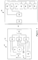
- Figure 1 is a block diagram of a computer system with a microphone mounted within a mouse.
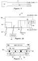
- Figure 2 is a schematic diagram of a microphone circuit.
- Figure 2A is a rear view of a typical computer depicting various alternative connectors.
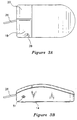
- Figure 3A is a partial cutaway top view of a mouse having a microphone therein.
- Figure 3B is a side view of the mouse of Figure 3A.
- Figure 4 is a depiction of the screen icons used with one embodiment of the present invention.
- a mouse 10 is coupled to a computer 35 via a transmission line 26.
- the term “mouse” is used broadly and includes any computer pointing and command entry device, such as a desktop mouse, a trackball device, Microsoft's Ballpoint® mouse, a joystick, or the like.
- the mouse 10 includes a housing 12, and within the housing a cursor movement control device having a rotatable ball 14, an encoder 16, switches 18 and 20, and a microphone 28.
- cursor control device includes a rotatable ball and encoder, but may also include a joystick or optical controllers a well.
- An electric circuit 24 is coupled to the encoder 16; an electric circuit 22 is coupled to the switches 18 and 20; and an electric circuit 30 is coupled to the microphone 28.
- a battery power supply 32 such as 3 volts, is optionally coupled to the electrical circuit to provide a power supply for the microphone and audio data signal.
- the respective circuits 22, 24, and 30 are coupled to a transmission circuit 25, within the mouse 10.
- the transmission line 26 is any acceptable transmission line, including an electrical wire cable, or an optical beam, or a radio frequency (RF) channel.
- the appropriate transmission circuit 25 is selected to provide transmission on the line 26; thus the transmission circuit 25 may be a simple wire connector, an optic coupler, or a RF transmitter.
- Power is supplied to the mouse 10 in any suitable way.
- the mouse 10 receives power from the computer 35 via some of the wires in the transmission line cable 26, the power line being in the same cable with the data lines.
- power is provided by battery 32 within the housing 12, as would be useful for an optical or RF transmission line 26.
- Using a battery 32 in the housing 12 for power has the advantage of providing a clean power supply and few or no noise filter elements are required.
- the appropriate filters are placed in the mouse 10 to provide a clean audio signal output. Filters to remove noise from a power supply line to make it suitable for audio data are generally known in the art and any suitable filter is acceptable.
- microphone 28 is mounted within the housing 12.
- the microphone 28 transduces the audio data into an electrical audio data signal.
- the term microphone includes devices capable of transducing audio signals into electrical signals such as electret, condenser, or moving-coil microphones, accelerometers, pressure transducers, or piezoelectric transducers.
- Audio circuitry 30 within the housing 12 receives the output from the microphone 28.
- an electret microphone is used for microphone 28 due to its high quality, low cost, ruggedness, small size, and the simplicity of associated circuitry 30.
- the circuit 30 for an electret microphone includes a current-limiting resistor 31 in series with the power supply line 38 and a capacitor 32 in series with the output line 33.
- the circuit 30 can be any suitable circuit for connecting to the microphone 28 to provide the desired electrical output on line 33.
- the circuit 30 may be a digital encoding circuit, a simple wire (for a moving coil microphone), an optical encoder circuit, a wheatstone bridge, or the like.
- the output 33 of the audio circuit 30 is input to the transmission circuit 25.
- output of the mouse 10 is connected to a receiving circuit 34 within the computer 35.
- the receiving circuit 34 is a connector directly coupled to the wire transmission line 26 and receives the signals from the mouse 10.
- a signal separator circuit 36 separates the electrical audio data signal from the other signal output by the mouse 10.
- the electrical signals corresponding with the rotational movement of the rotatable ball and the electrical signals associated with the switches are routed to a mouse signal circuit 37, and the electrical audio data signal from the microphone 28 is routed to a computer sound board 38.
- Computer sound boards are well-known in the industry and are commercially available for most computers.
- the computer sound board 38 can be a stand-alone board solely devoted to audio circuits, or alternatively, it can be audio circuitry mounted on a board having chips with other functions thereon, such as video chips, etc. In one embodiment, the sound board 38 includes a clean, stable power supply for a microphone. Such computer sound boards or audio circuits 38 usually include analog to digital converters and circuitry to interface with the CPU 40 to permit manipulation, storage, and read-out of audio signals.
- the mouse 10 is plugged via wire cable 26, directly into a standard serial port, the serial port being part of the receiving circuit 34.
- unused wires in the serial cable and connectors of the serial port are used to carry the electrical audio signal. That is, a serial port may have nine pins ad a serial cable nine wires; today, only six or seven of those pins are used for power and mouse functions, and two pins are unused. These pins can be used to carry the audio data signal. Alternatively, the audio data can be superimposed on top of the cursor movement control data and carried on the same wires.
- the audio wires are routed to the sound board 38.
- the serial port may be positioned on the sound board 38, the serial port providing the functions of receiving circuit 34, signal separator 36, and connection to the sound board 38.
- the combined board saves space in the computer by requiring only a single board rather than two separate boards.
- the receiver 34 is an optocoupler or an RF receiver.
- a typical computer system 35 includes a central processing unit 40; a volatile memory 42; a non-volatile memory 44, such as disk storage unit; a keyboard 46; a display unit 48; and a mouse signal circuit 37.
- the mouse 10 may be coupled to any typical computer and, with the appropriate software, store the electrical audio data in either memory 42 or non-volatile memory 44, such as a hard disk.
- Figure 2A shows the back of the computer 35 with various alternative connectors that may be used with the present invention.
- the computer 35 has a power supply 80, contained within the case 82, and is powered by 120 VAC through a standard power cord 84, or alternatively by a battery if computer 35 is portable.
- the computer 35 also has a keyboard 46, and typically has several additional slots that are used for various electrical circuit boards as selected by a user, such as a modem 49, an extra memory board, an enhanced video board, a line printer board, or the like. Many of these boards will have their own connector to allow I/O directly to the board, or through the board to other circuits in the computer 35.
- modem board 49 includes a connector 86
- serial port board 34 includes a connector 88
- sound board 38 includes a connector 90.
- the mouse of the present invention may be coupled to the computer through a serial port 34, and derive power solely through the serial port connector 88 as described above.
- the mouse 10 may be coupled to the connector 90 of the sound board 38.
- the sound board 38 includes a circuit that provides a clean source of power for the mouse 10 and the microphone within the mouse. Having a separate power supply for the microphone ensures that a clean and properly controlled source of power is always available for a external microphone.
- the power supply from the serial port connector 88 can be used, but the power supply of the serial port is subject to significant noise that may cause noise on the audio signal.
- the noise may be filtered out by a filter circuit within the mouse 10, if desired, but the need for a filter in the mouse 10 can be avoided by providing a circuit for a clean, stable power supply for a microphone on the sound board 38. Any circuit which provides a clean power supply is acceptable; many are known in the art.
- the sound board 38 separates the microphone signals for processing by the audio interface circuit of the sound board, while the signals associated with the mouse are processed by a mouse interface circuit on the sound board or routed to the appropriate circuit within the computer 35.
- FIGs 3A and 3B illustrate a computer mouse 10 having the microphone 28 mounted therein
- the microphone 28 is mounted in the side of the mouse 10, near the switches 18, 20.
- the mouse 10 is shown in cutaway to provide a topside view of the microphone 28 within the mouse 10, though the microphone will not usually be visible to a user.
- holes 51 are provided to pass the sound into the mouse housing 12 to impinge on microphone 28.
- the location of the microphone 28 is selected to place it near the user's mouth when the mouse 10 is held in the hand while depressing switches 18 or 20 with the fingers.
- the position of the microphone 28 in the housing 12 varies for different physical configurations of computer command apparatus.
- the microphone 28 is mounted in the bottom or on the top of the housing 12 in one embodiment.
- the invention is used as follows.
- the audio software program is loaded by depressing switch 18 while the cursor is on an audio program icon.
- the computer loads the audio software program and displays a window on the screen, which provides options to enter commands into the computer.
- a portion of the computer memory, either RAM 42 or nonvolatile memory 44, is automatically designated as the current tape for the audio data storage.
- the term "tape" does not necessarily refer only to an ordinary magnetic tape, but may refer to a block of computer memory that has been designated as a tape. Generally, the blocks are allocated by sire to hold 60 seconds of audio recording, but the tape may be any sire the user desires to allocate, ten minutes for example, up to the computer's storage capacity.
- the audio data can be stored on any suitable medium in either analog or digital format, or even on a standard audio tape coupled to the computer 35.
- the audio data is output directly on a telephone line as voice data through a modem 49 in the computer 35, as explained later herein.
- Figure 4 illustrates a sample menu for an audio software program. Icons for record 50, play 52, stop 54, and pause 56 are displayed. Alternatively, icons for fast forward, rewind, return to start, load new tape, and go to the end of tape are also displayed. A time meter 58 in the form of a scroll bar shows graphically how many seconds (or minutes) have been recorded and how much time is left on the tape.
- the scroll bar tracks the recording and playback time on the loaded tape. As the user records or plays back from a tape, the scroll bar moves to the right, indicating how much time is left before the maximum time limit is reached.
- the time limit indicator shows the maximum storage space available in minutes or seconds in that particular data file. Presently, most data files have a maximum storage capability of sixty seconds. Because audio data, when digitized, takes up a great deal of memory, the standard audio tape is sixty seconds in length. If a large, hard disk drive is provided, up to sixty minutes of recording could be provided. Of course, as storage techniques for audio data improve, a standard computer floppy disk will likely be able to hold several audio files and a single floppy-disk may take the place of a dictaphone-recorded magnetic tape.
- the user moves the mouse so that the screen cursor points at the audio record icon 50 as shown in Figure 4.
- the user then depresses (clicks) the primary switch 18 to enable the recording of the audio input.
- Audio input is preferably recorded while the user is holding the mouse 10 ad speaking into the microphone 28, while depressing the primary mouse switch 18.
- the audio data is recorded and the electrical audio data signal from the microphone 28 is continuously stored in the computer so long as the user maintains the switch 18 in the depressed position. Releasing the switch 18 on the mouse automatically terminates the input of electrical audio data signal from the microphone.
- the audio data is recorded after the switch 18 has been released and continues until the stop icon 54 is clicked on.
- the present invention includes a automatic rewind feature. If the user depresses the primary mouse switch 18 a second time with the same tape as the storage tape, the prior message is erased and the new audio data is recorded in place of the first message.
- Playback of the audio data is accomplished by again using the mouse 10a a pointing and command entry device.
- the user loads the desired audio file, selects the playback command option by moving the mouse so that the cursor points to the playback icon 52 and clicks the primary mouse switch 18.
- the computer automatically plays out the message through the sound board 38 to a speaker within the computer 35 or a stand-alone speaker.
- the clicking on the stop icon 54 stops the playback or recording of audio data. If the data file has been imbedded in an application program, the data field to which the audio commentary is attached will be highlighted during the playback on the display 48 to indicate to the user than an audio commentary is attached to that particular data field.
- clicking switch 18 on the record icon 50 always records audio data at the beginning of the current tape.
- Clicking switch 20 on the record icon appends the audio data to the end of the audio data already stored on the loaded tape. Because the audio data is stored in a computer memory, random access is effectively permitted. The user can instantly access the beginning, end, or middle portions of any tape. This is an improvement over current audio magnetic tapes which must be accessed serially and a user must wait for the tape rewind to start at the beginning or fast forward to the end, which may take several minutes.
- the very same switches on mouse 10 that enter commands into the computer to store, playback, and manipulate software data files are also used to manipulate audio data.
- the user points and clicks switch 18, that is, places the cursor on an icon and depresses switch 18, to load any program, pull down a menu, select an item from a menu, etc. She points and clicks with switch 18 to load the audio program in this way. She uses the very same switches, 18 and 20, to record and playback audio data that are used to enter commands into the computer.
- the very same hardware, a mouse 10 and a computer 35 having a hard drive 44 are also used for both functions. The functions which previously required two machines can now be performed by one machine that is operated in a user-friendly, well-known way.
- a computer with a modem can automatically dial, ring, and connect to a standard telephone line.
- the user can mimic, and thus replace, the existing telephone hardware as well.
- the invention is used as a standard telephone by dialing the desired number through the modent, and waiting for a person to answer.
- the ring and the other person talking are output on the computer's speaker, and the user talks to them through the microphone in the mouse.
- a speaker can be placed within the mouse 10 a well, just as a telephone handset includes both a microphone and a speaker.
- a stand-alone speaker of good quality is coupled to the computer 35 to provide high-quality audio output
- the same telephone line that is used to transmit digital data via the modem is now used to transmit audio telephone communication through the modem from the computer.
- the data is usually not recorded, though this is easily possible.
- Having a microphone, and optionally a speaker, within the mouse 10 permits the computer and mouse combination to perform the standard telephone function, further reducing the desk space taken up by machines.
- the computer could be used as a standard dictaphone a well, transmitting the stored files digitally on computer network transmission lines to a separate location for transcribing.
- the audio program provides the following options for a user file, edit, and help.
- the file menu permits a user to load any selected audio file into the audio program from a disk or save the audio tape just recorded to a disk.
- the file menu provides a new command to create a new, empty memory location for recording; an open command to open an existing audio file; a close command to close an existing audio file without exiting the audio program; a save command to save changes made to an audio file; a save as is command to specify an audio file and save changes to that file; and an exit.
- the edit menu provides numerous edit commands, such as cut and paste to various files, an undo command, and an option command that allows a user to customize the audio settings as desired.
- the help menu provides an index, a tutorial, and other features useful in instructing a user how to operate the audio program.
- the audio commentary may be imbedded or attached to numerous application programs, such as Microsoft Word or Microsoft Excel, to provide audio commentary on a written document.
- application programs such as Microsoft Word or Microsoft Excel
- To imbed an audio commentary in a application program such a Microsoft Excel the user highlights the data field on the display unit 48 to which the audio commentary will be attached, pulls-up the audio program menu, and selects the audio record mode, as has been described.
- the audio commentary is completed, and will automatically attach to that particular data field in the Microsoft Excel data file.
- the same technique may be used to imbed audio commentary in numerous other application programs.
Applications Claiming Priority (2)
| Application Number | Priority Date | Filing Date | Title |
|---|---|---|---|
| US77992691A | 1991-10-21 | 1991-10-21 | |
| US779926 | 1991-10-21 |
Publications (1)
| Publication Number | Publication Date |
|---|---|
| EP0538794A1 true EP0538794A1 (fr) | 1993-04-28 |
Family
ID=25118023
Family Applications (1)
| Application Number | Title | Priority Date | Filing Date |
|---|---|---|---|
| EP92117927A Withdrawn EP0538794A1 (fr) | 1991-10-21 | 1992-10-20 | Combinaison souris d'ordinateur et microphone et méthode d'utilisation |
Country Status (7)
| Country | Link |
|---|---|
| EP (1) | EP0538794A1 (fr) |
| JP (1) | JPH06202803A (fr) |
| KR (1) | KR930008597A (fr) |
| AU (1) | AU2712492A (fr) |
| BR (1) | BR9204083A (fr) |
| CA (1) | CA2080802A1 (fr) |
| TW (1) | TW247950B (fr) |
Cited By (8)
| Publication number | Priority date | Publication date | Assignee | Title |
|---|---|---|---|---|
| EP0633520A1 (fr) * | 1993-07-01 | 1995-01-11 | Koninklijke Philips Electronics N.V. | Télécommande avec commande vocale |
| EP0712068A1 (fr) * | 1994-11-14 | 1996-05-15 | AT&T Corp. | Système d'interfaçage pour ordinateur et pour télécommunications |
| WO1998025221A2 (fr) * | 1996-12-07 | 1998-06-11 | Appli.Com Gmbh Kommunikationsdesign + Engineering | Procede de declenchement de fonctions d'un programme informatique |
| US6003072A (en) * | 1993-07-01 | 1999-12-14 | U.S. Philips Corporation | Multi-media data processing device with remote control device that also has voice input means and hand-sized unit for use in such data processing device |
| EP0984351A2 (fr) * | 1998-09-02 | 2000-03-08 | Fujitsu Limited | Ordinateur portatif du type notebook avec un dispositif d' entrée infrarouge multimode détachable |
| WO2002001491A1 (fr) * | 2000-06-28 | 2002-01-03 | Dynavision Technology Limited | Controleur d'ordinateur |
| WO2002093342A2 (fr) * | 2001-05-16 | 2002-11-21 | Kanitech International A/S | Dispositif de commande pour ordinateur avec moyens de detection optiques et son utilisation |
| WO2003042802A2 (fr) * | 2001-11-16 | 2003-05-22 | 3Dconnexion Gmbh | Appareil de saisie, webcam et ecran a fonction d'entree vocale |
Families Citing this family (2)
| Publication number | Priority date | Publication date | Assignee | Title |
|---|---|---|---|---|
| JP2003511992A (ja) * | 1999-10-13 | 2003-03-25 | コーニンクレッカ フィリップス エレクトロニクス エヌ ヴィ | 音声信号入力手段と制御信号入力手段とを伴う装置 |
| KR100710060B1 (ko) * | 2005-07-11 | 2007-04-20 | 주식회사 애트랩 | 마이크로폰 내장형의 마우스 |
Citations (1)
| Publication number | Priority date | Publication date | Assignee | Title |
|---|---|---|---|---|
| US4866602A (en) * | 1983-11-02 | 1989-09-12 | Microsoft Corporation | Power supply for a computer peripheral device which positions a cursor on a computer display |
-
1992
- 1992-10-16 CA CA002080802A patent/CA2080802A1/fr not_active Abandoned
- 1992-10-19 AU AU27124/92A patent/AU2712492A/en not_active Abandoned
- 1992-10-20 TW TW081108326A patent/TW247950B/zh active
- 1992-10-20 EP EP92117927A patent/EP0538794A1/fr not_active Withdrawn
- 1992-10-21 KR KR1019920019320A patent/KR930008597A/ko not_active Application Discontinuation
- 1992-10-21 BR BR929204083A patent/BR9204083A/pt not_active Application Discontinuation
- 1992-10-21 JP JP4283198A patent/JPH06202803A/ja not_active Withdrawn
Patent Citations (1)
| Publication number | Priority date | Publication date | Assignee | Title |
|---|---|---|---|---|
| US4866602A (en) * | 1983-11-02 | 1989-09-12 | Microsoft Corporation | Power supply for a computer peripheral device which positions a cursor on a computer display |
Non-Patent Citations (5)
| Title |
|---|
| "MOUSE WITH EARS.", RESEARCH DISCLOSURE., MASON PUBLICATIONS, HAMPSHIRE., GB, no. 332., 1 December 1991 (1991-12-01), GB, pages 908., XP000274613, ISSN: 0374-4353 * |
| 'INSIDE MACINTOSH,VOLUME 6' June 1991 , APPLE COMPUTER INC , CUPERTINO, CA ,US * |
| PAGE 'INTRODUCTION TO SOUND BLASTER' * |
| PATENT ABSTRACTS OF JAPAN vol. 013, no. 361 (P-917)11 August 1989 & JP-A-11 19 821 ( AOKI GOICHI ) * |
| 'SOUND BLASTER USER REFERENCE MANUAL' October 1991 , CREATIVE LABS , SANTA CLARA,CA, US * |
Cited By (15)
| Publication number | Priority date | Publication date | Assignee | Title |
|---|---|---|---|---|
| US6003072A (en) * | 1993-07-01 | 1999-12-14 | U.S. Philips Corporation | Multi-media data processing device with remote control device that also has voice input means and hand-sized unit for use in such data processing device |
| EP0633520A1 (fr) * | 1993-07-01 | 1995-01-11 | Koninklijke Philips Electronics N.V. | Télécommande avec commande vocale |
| EP0712068A1 (fr) * | 1994-11-14 | 1996-05-15 | AT&T Corp. | Système d'interfaçage pour ordinateur et pour télécommunications |
| WO1998025221A2 (fr) * | 1996-12-07 | 1998-06-11 | Appli.Com Gmbh Kommunikationsdesign + Engineering | Procede de declenchement de fonctions d'un programme informatique |
| WO1998025221A3 (fr) * | 1996-12-07 | 2001-06-28 | Appli Com Gmbh Kommunikationsd | Procede de declenchement de fonctions d'un programme informatique |
| EP1457918A1 (fr) * | 1998-09-02 | 2004-09-15 | Fujitsu Limited | Ordinateur portatif du type notebook avec un dispositif d' entrée infrarouge multimode détachable |
| EP0984351A2 (fr) * | 1998-09-02 | 2000-03-08 | Fujitsu Limited | Ordinateur portatif du type notebook avec un dispositif d' entrée infrarouge multimode détachable |
| US7298359B2 (en) | 1998-09-02 | 2007-11-20 | Fujitsu Limited | Notebook computer with detachable infrared multi-mode input device |
| EP0984351A3 (fr) * | 1998-09-02 | 2003-05-07 | Fujitsu Limited | Ordinateur portatif du type notebook avec un dispositif d' entrée infrarouge multimode détachable |
| EP1691264A1 (fr) * | 1998-09-02 | 2006-08-16 | Fujitsu Limited | Ordinateur portatif du type notebook avec un dispositif d' entrée infrarouge multimode détachable |
| WO2002001491A1 (fr) * | 2000-06-28 | 2002-01-03 | Dynavision Technology Limited | Controleur d'ordinateur |
| WO2002093342A3 (fr) * | 2001-05-16 | 2004-02-26 | Kanitech Internat A S | Dispositif de commande pour ordinateur avec moyens de detection optiques et son utilisation |
| WO2002093342A2 (fr) * | 2001-05-16 | 2002-11-21 | Kanitech International A/S | Dispositif de commande pour ordinateur avec moyens de detection optiques et son utilisation |
| WO2003042802A3 (fr) * | 2001-11-16 | 2004-04-01 | 3Dconnexion Gmbh | Appareil de saisie, webcam et ecran a fonction d'entree vocale |
| WO2003042802A2 (fr) * | 2001-11-16 | 2003-05-22 | 3Dconnexion Gmbh | Appareil de saisie, webcam et ecran a fonction d'entree vocale |
Also Published As
| Publication number | Publication date |
|---|---|
| CA2080802A1 (fr) | 1993-04-22 |
| KR930008597A (ko) | 1993-05-21 |
| AU2712492A (en) | 1993-04-22 |
| TW247950B (fr) | 1995-05-21 |
| JPH06202803A (ja) | 1994-07-22 |
| BR9204083A (pt) | 1993-05-18 |
Similar Documents
| Publication | Publication Date | Title |
|---|---|---|
| US5444768A (en) | Portable computer device for audible processing of remotely stored messages | |
| CA1326542C (fr) | Systeme de dictee/transcription modulaire | |
| US6546262B1 (en) | Cellular telephone accessory device for a personal computer system | |
| US6529920B1 (en) | Multimedia linking device and method | |
| JPH0651941A (ja) | 音声注釈を備えた携帯型コンピュータ | |
| EP0538794A1 (fr) | Combinaison souris d'ordinateur et microphone et méthode d'utilisation | |
| US6697841B1 (en) | Dictation system employing computer-to-computer transmission of voice files controlled by hand microphone | |
| US4328397A (en) | Method and apparatus for controlling predetermined machine conditions, such as the operating conditions of a dictation/transcription machine | |
| US7769479B2 (en) | Audio recording apparatus, audio recording method and audio recording program | |
| EP0261680B1 (fr) | Appareil de dictée téléphonique | |
| DE10004284A1 (de) | Tragbares Datenaufnahme- und/oder Datenwiedergabegerät | |
| EP0706114A2 (fr) | Dispositif et méthode d'enregistrement et d'organisation de données audio | |
| US7027978B2 (en) | Voice recording and reproducing apparatus, information processing apparatus, and recording medium having recorded an information processing program | |
| CN1549545B (zh) | 一种实现连接网络及大容量存储的多媒体装置 | |
| US4722077A (en) | Transcription control over plural interconnected modules | |
| US6314331B1 (en) | Enhanced user control operations for sound recording system | |
| JP4332927B2 (ja) | 編集装置 | |
| CN101488359B (zh) | 多重录音装置 | |
| JP2003131698A (ja) | 音声記録再生装置 | |
| KR102160229B1 (ko) | 사용자 맞춤형 페이지 처리 방법 및 휴대 단말 | |
| EP0606755A1 (fr) | Appareil à dicter constitué d'une combinaison d'un ordinateur portatif et d'un combiné | |
| CN200986697Y (zh) | Usb界面的录音用麦克风装置 | |
| JP4282335B2 (ja) | デジタルレコーダ | |
| KR100634154B1 (ko) | 음성 녹음장치와 인터페이스 장치가 구비된 컴퓨터 시스템 | |
| JP2004094113A (ja) | 音声データ処理装置及び音声データ処理プログラム |
Legal Events
| Date | Code | Title | Description |
|---|---|---|---|
| PUAI | Public reference made under article 153(3) epc to a published international application that has entered the european phase |
Free format text: ORIGINAL CODE: 0009012 |
|
| AK | Designated contracting states |
Kind code of ref document: A1 Designated state(s): AT BE CH DE DK ES FR GB GR IE IT LI LU MC NL PT SE |
|
| 17P | Request for examination filed |
Effective date: 19930303 |
|
| 17Q | First examination report despatched |
Effective date: 19930709 |
|
| STAA | Information on the status of an ep patent application or granted ep patent |
Free format text: STATUS: THE APPLICATION IS DEEMED TO BE WITHDRAWN |
|
| 18D | Application deemed to be withdrawn |
Effective date: 19931120 |