EP0537814B1 - Mehrstationbussystem mit Mitteln zum Aufrufen und Aktualisieren allgemein relevanter Information, insbesondere einer Stationsadresse, sowie Station zur Verwendung in einem derartigen System - Google Patents
Mehrstationbussystem mit Mitteln zum Aufrufen und Aktualisieren allgemein relevanter Information, insbesondere einer Stationsadresse, sowie Station zur Verwendung in einem derartigen System Download PDFInfo
- Publication number
- EP0537814B1 EP0537814B1 EP92202716A EP92202716A EP0537814B1 EP 0537814 B1 EP0537814 B1 EP 0537814B1 EP 92202716 A EP92202716 A EP 92202716A EP 92202716 A EP92202716 A EP 92202716A EP 0537814 B1 EP0537814 B1 EP 0537814B1
- Authority
- EP
- European Patent Office
- Prior art keywords
- station
- address
- communication system
- updating
- stations
- Prior art date
- Legal status (The legal status is an assumption and is not a legal conclusion. Google has not performed a legal analysis and makes no representation as to the accuracy of the status listed.)
- Expired - Lifetime
Links
Images
Classifications
-
- H—ELECTRICITY
- H04—ELECTRIC COMMUNICATION TECHNIQUE
- H04L—TRANSMISSION OF DIGITAL INFORMATION, e.g. TELEGRAPHIC COMMUNICATION
- H04L12/00—Data switching networks
- H04L12/28—Data switching networks characterised by path configuration, e.g. LAN [Local Area Networks] or WAN [Wide Area Networks]
- H04L12/2803—Home automation networks
- H04L12/2816—Controlling appliance services of a home automation network by calling their functionalities
- H04L12/2821—Avoiding conflicts related to the use of home appliances
-
- H—ELECTRICITY
- H04—ELECTRIC COMMUNICATION TECHNIQUE
- H04L—TRANSMISSION OF DIGITAL INFORMATION, e.g. TELEGRAPHIC COMMUNICATION
- H04L12/00—Data switching networks
- H04L12/28—Data switching networks characterised by path configuration, e.g. LAN [Local Area Networks] or WAN [Wide Area Networks]
- H04L12/40—Bus networks
- H04L12/403—Bus networks with centralised control, e.g. polling
-
- H—ELECTRICITY
- H04—ELECTRIC COMMUNICATION TECHNIQUE
- H04L—TRANSMISSION OF DIGITAL INFORMATION, e.g. TELEGRAPHIC COMMUNICATION
- H04L61/00—Network arrangements, protocols or services for addressing or naming
- H04L61/50—Address allocation
- H04L61/5038—Address allocation for local use, e.g. in LAN or USB networks, or in a controller area network [CAN]
-
- H—ELECTRICITY
- H04—ELECTRIC COMMUNICATION TECHNIQUE
- H04L—TRANSMISSION OF DIGITAL INFORMATION, e.g. TELEGRAPHIC COMMUNICATION
- H04L61/00—Network arrangements, protocols or services for addressing or naming
- H04L61/50—Address allocation
- H04L61/5046—Resolving address allocation conflicts; Testing of addresses
-
- H—ELECTRICITY
- H04—ELECTRIC COMMUNICATION TECHNIQUE
- H04L—TRANSMISSION OF DIGITAL INFORMATION, e.g. TELEGRAPHIC COMMUNICATION
- H04L61/00—Network arrangements, protocols or services for addressing or naming
- H04L61/50—Address allocation
- H04L61/5092—Address allocation by self-assignment, e.g. picking addresses at random and testing if they are already in use
-
- H—ELECTRICITY
- H04—ELECTRIC COMMUNICATION TECHNIQUE
- H04L—TRANSMISSION OF DIGITAL INFORMATION, e.g. TELEGRAPHIC COMMUNICATION
- H04L9/00—Cryptographic mechanisms or cryptographic arrangements for secret or secure communications; Network security protocols
- H04L9/40—Network security protocols
-
- H—ELECTRICITY
- H04—ELECTRIC COMMUNICATION TECHNIQUE
- H04L—TRANSMISSION OF DIGITAL INFORMATION, e.g. TELEGRAPHIC COMMUNICATION
- H04L12/00—Data switching networks
- H04L12/28—Data switching networks characterised by path configuration, e.g. LAN [Local Area Networks] or WAN [Wide Area Networks]
- H04L12/2803—Home automation networks
- H04L12/2807—Exchanging configuration information on appliance services in a home automation network
-
- H—ELECTRICITY
- H04—ELECTRIC COMMUNICATION TECHNIQUE
- H04L—TRANSMISSION OF DIGITAL INFORMATION, e.g. TELEGRAPHIC COMMUNICATION
- H04L12/00—Data switching networks
- H04L12/28—Data switching networks characterised by path configuration, e.g. LAN [Local Area Networks] or WAN [Wide Area Networks]
- H04L12/2803—Home automation networks
- H04L2012/2847—Home automation networks characterised by the type of home appliance used
- H04L2012/2849—Audio/video appliances
-
- H—ELECTRICITY
- H04—ELECTRIC COMMUNICATION TECHNIQUE
- H04L—TRANSMISSION OF DIGITAL INFORMATION, e.g. TELEGRAPHIC COMMUNICATION
- H04L12/00—Data switching networks
- H04L12/28—Data switching networks characterised by path configuration, e.g. LAN [Local Area Networks] or WAN [Wide Area Networks]
- H04L12/2803—Home automation networks
- H04L2012/2847—Home automation networks characterised by the type of home appliance used
- H04L2012/285—Generic home appliances, e.g. refrigerators
Definitions
- the invention relates to a communication system having multiple and uniformly weighted stations (2, 3, 4) that are interconnected by a shared digital bus (1), wherein a particular station, comprising a globally relevant information item, comprises means (22, 32, 42) for transmitting a data packet representing such information item for unanimous counter signalization thereto by at least a relevant subset of actually interconnected stations thereto, but upon absence of such unanimous counter signalization initiating an updating action with respect to its own relevant information item.
- NL-A-8900717 describes such a system for audio/video stations. Uniformly-weighted is understood as meaning that there is no single station present that acts as overall controller of the bus interactions.
- a first station may operate as master, whereas one or more second stations would operate as slaves. A subsequent transfer could then have a different master station.
- the stations can have various different priority levels, activity frequencies, and hardware provisions.
- the bus as referred to supra is metaphoric for its medium, that may be single- or plural channel, galvanically interconnected, optical, radio broadcast, infrared, or other.
- the bus medium may be uniform or mixed, such as a wired interconnection, that has a two-way station for external communication of infrared signals.
- the organization may have provisions for AND-ing/OR-ing logical states generated by the bus-connected stations. In other organizations, such provision would be irrelevant.
- the nature of the stations may be various, but a particular field of use would be home-based systems.
- the stations could be devices for audio/video entertainment, home-environmental control (lighting, temperature, humidity), devices for executing household chores, telecommunication, safety control, or other.
- a particular hazard of such system is the low degree of organizational consistency on the level of the stations themselves, as exemplified by:
- the invention solves the problem in that it is characterised in that said particular station is conceived to transmit said data packet recurrently with a predetermined maximum recurrence interval.
- the originating station does not address the stations of the relevant subset, because it would not be sure which stations would actually be present in the subset; it would only know that any station not joining in the unanimous counter signalization, whereas it should actually have joined indeed, thereby signals that the originally transmitting station had an information that were outdated or otherwise erroneous. Thereupon, the original station starts with updating.
- the unanimous counter signalization indicates, that all other stations are in unison about the original information item.
- the physical representation of the unanimity may be various, such as by wired-OR (a -one- signal could in particular circumstances signal a discord), or wired-AND.
- the counter signalization can be as well by a message, wherein the set of messages generated would indicate unanimity or otherwise.
- all messages could indeed contain identical signalization items, whereupon the original station would check the unanimity.
- any such message could, on a suitable communication layer, such as bit, word, or other, by its occurrence alone, signal lack of unanimity.
- the original station need not always transfer the item itself, but also an indirect indication, abstract, or other representation could suffice. It is not strictly necessary that all other stations connected should actually have the facility for counter signalizing. Certain stations could be slave-only stations. Alternatively, a station could be too busy to answer. If it would not concur with the unanimity, it could signal so upon the end of the next recurrence interval. Various other reasons could put a particular station out of the relevant subset specified above.
- the globally relevant information is an address of the particular station itself.
- addresses should be unique, and the updating would take care of making the address unique again.
- Various effects could cause two or even more stations to have the same address, and the present invention would make the system stabilized again on a unique address for all stations that would observe the polling operation.
- Another globally relevant information would be a value of the actual or real time. The invention would keep the actual value thereof correct, even if the original station would become temporarily disturbed and would not know which other station to address for acquiring the correct value.
- the updating may go according to a predetermined pattern. For an address, successive incrementations by one would be good.
- updating according to a pseudo-random series would keep two updating stations apart from each other. Especially in a start-up situation where any station may start from a default address -zero-, this would be advantageous: respective stations could then follow respective different sequences.
- the result of the updating may be signalled to any relevant station, either by repeating transmitting a data packet formatted like the original one, but with the now updated information item, or by effectively addressing any station present, for example, by adding destination default address such as -zero-. This procedure keeps other stations abreast of any new developments.
- the system comprising distinguishing means for distinguishing among actual recurrence intervals of respective ones among said stations.
- Each station could have its own specific recurrence interval.
- the recurrence interval could be a time-variable quantity in any relevant station.
- the invention also relates to a station for use in such communication system.
- Various advantageous aspects are recited in dependent Claims.
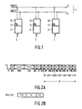
- Figure 1 shows diagrammatically a single-channel communication bus system. It comprises a communication bus 1 consisting of two data lines 11 and 12. In this case three stations 2, 3 and 4 are connected to this communication bus. Each station comprises an apparatus 21, 31, 41 which is connected to the data lines 11 and 12 by means of an interface circuit 22, 32, 42. Such an apparatus may be a TV monitor, a video recorder, an audio recorder, an audio tuner, a controllable set of lighting elements, etcetera.
- the communication bus is intended to transmit control signals from a first station to a second station. Some stations will act as master stations and others as slave stations. Some stations will act as transmitters of data, some as receivers. All kind of mixed or alternating situations are possible.
- the communication operations on the communication bus are performed by the interface circuits.
- a particular advantageous realization of the bus is D 2 B, that is single channel, twisted pair.
- the interface circuit may be a MAB 8051 microcontroller, referred to in: Single-Chips 8-Bit Microcontrollers, User manual 1988, Philips Electronic Components and Materials Division; Chapter 3: The MAB 8051/C51/52 microcontroller family; Chapter 11: The D 2 B specification.
- each interface circuit has a memory location 23, 33, 43 in which a station address is stored.
- a typical station address comprises twelve bits.
- FIG. 2A The structure of a communication operation on an information level is shown in Figure 2A. Such an operation starts with a start bit ST. It is followed by a mode field MO in which three mode indication bits are transmitted. They indicate the rate at which the following information will be transmitted.
- master station address field MSA the twelve-bit master station address is transmitted from the station wishing to transmit information to a destination station. The twelve-bit destination station address is transmitted in the destination station address field SSA. If a station recognizes the destination address as its own address, it transmits an acknowledge code in acknowledge code field ACI. If this acknowledge code is not received, it means that the destination station is not present or does not function or that the destination station address is received in a mutilated form. No distinction is made between these three possibilities.
- the communication is discontinued after the acknowledge code field. If the acknowledge code has effectively been received, the master station transmits a control code of, for example four bits in control field CF. After reception of this control code, the destination station again transmits an acknowledge code in acknowledge code field ACII. If this second acknowledge code is not received by the master station, the communication is discontinued. If the master station has received this second acknowledge code a data field DF occurs.
- the data field may be divided into various data or command subfields, each containing a data byte DB, and end of data signalization EOD, and acknowledge bit interval ACIII. Absence of the latter may trigger repeat of the most recent subfield. If EOD is positive, the transmission may terminate.
- the structure of a station address is shown at Figure 2B. It comprises a service address SA, a type address TA and a follower address FA.
- the service address SA comprises, for example four bits and can thus distinguish sixteen services, for example an audio-video service, a washing service, a cooking/baking service etcetera.
- the type address TA comprises, for example five bits so that thirty-two stations can be distinguished within one service. For example, within the washing service a distinction can be made between a washing machine, a drier, a dish washer, etcetera and within the audio-video service a distinction can be made between a TV monitor, a tuner, a video recorder, etcetera.
- the user may have a number of apparatuses of the same type, for example, two or more video recorders.
- the follower address FA enables him to distinguish between these apparatuses of the same type. By three bits, eight apparatuses of the same type can be distinguished.
- a station address comprises a service address, a type address and a follower address.
- Service address and type address have been assigned by a manufacturers which has programmed them in the station address memory of the interface circuit.
- Programming of the follower address will be left to the user and does not take place until after the relevant apparatus has been connected to the communication bus 1 by means of the interface circuit.
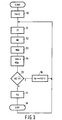
- this interface circuit has an initialization program with the steps shown in Figure 3 and which is performed as soon as the apparatus is switched on. More particularly the follower address FA is set to zero in a first step 50.
- the last used follower address FA is then stored in the station address memory in a step 57, with which this initialization program comes to an end.
- a master station does not get access to the communication bus until a so-called arbitration procedure has been formed.
- this arbitration procedure the mode indication bits, the service address bits and type address bits and now also the follower address bits are involved.
- the stop block actually starts a particular time-out, after which the system again reverts to block 51, and the same procedure as for initialization ensues.
- a particular provision, not shown, may be taken in case the loop of Figure 3 were cycled continuously, because in that case no free address would be available. For brevity this has not been shown in Figure 3.
- any unit has a unique code UI or some "random" generator for distinguishing itself from units of the same sort. As almost any unit must contain some NVRAM already, this memory may also contain such code.
- the randomness of the randomness generatior need not be extreme, inasmuch as any system usually contains only a moderate number of stations, say less than 50. Further, as long as a unit has not gained an address definitely, that is, when the unit has not yet decided which address to take, it may not respond to packets destined to its provisional address.
- the station leaves block 58 for block 51. Each station may have its own time-out value, or a time-out value that is randomized among successive passages through block 58. Also, the incrementing by 1 in block 56 may be changed into a quasi-randomized sequence of proposed station addresses.
- a suitable solution is by a maximum-length retrocoupled shift register because this couples the quasi randomness with the property that all addresses will be actually passed.
Landscapes
- Engineering & Computer Science (AREA)
- Computer Networks & Wireless Communication (AREA)
- Signal Processing (AREA)
- Computer Security & Cryptography (AREA)
- Automation & Control Theory (AREA)
- Small-Scale Networks (AREA)
- Data Exchanges In Wide-Area Networks (AREA)
- Maintenance And Management Of Digital Transmission (AREA)
- Monitoring And Testing Of Transmission In General (AREA)
Claims (10)
- Kommunikationssystem mit mehreren und gleichförmig gewichteten Stationen (2, 3, 4), die durch einen gemeinsamen digitalen Bus (1) miteinander verbunden sind, wobei eine bestimmte Station, die ein allgemein relevantes Informationselement enthält, Mittel (22, 32, 42) umfaßt zum Übertragen eines ein solches Informationselement darstellenden Datenpaketes bei entsprechender einstimmiger Zählersignalisierung an diese durch mindestens eine relevante Teilgruppe von tatsächlich hiermit verbundenen Stationen, die aber bei Abwesenheit einer solchen einstimmigen Zählersignalisierung eine Aktualisierungsaktion in Hinblick auf ihr eigenes relevantes Informationselement startet, dadurch gekennzeichnet, daß die genannte bestimmte Station konzipiert wird, um das genannte Datenpaket wiederholt mit einem vorgegebenen maximalen Wiederholungsintervall zu übertragen.
- Kommunikationssystem nach Anspruch 1, wobei die genannte allgemein relevante Information eine Adresse der bestimmten Station selbst ist.
- Kommunikationssystem nach Anspruch 1 oder 2, wobei jede physikalische Zählersignalisierung, die tatsächlich auftritt, Nicht-Einstimmigkeit bedeutet.
- Kommunikationssystem nach Anspruch 2, wobei das Datenpaket die genannte Adresse als eine Zieladresse enthält und die genannte Einstimmigkeit eine nicht vorhandene Signalisierung darstellt.
- Kommunikationssystem nach Anspruch 2 oder 4, wobei die genannte Aktualisierungsaktion eine neue Adresse entsprechend einem vorgegebenen Aktualisierungsmuster erzeugt.
- Kommunikationssystem nach einem der Ansprüche 1 bis 5, wobei nach der genannten Aktualisierung die Signalisierung des Ergebnisses der genannten Aktualisierung an eine beliebige andere relevante Station folgt.
- Kommunikationssystem nach einem der Ansprüche 1 bis 6, und mit Unterscheidungsmineln zum Unterscheiden zwischen den tatsächlichen Wiederholungsintervallen von entsprechenden unter den genannten Stationen.
- Kommunikationssystem nach einem der Ansprüche 1 bis 7, wobei der genannte digitale Bus einkanalig ist.
- Kommunikationssystem nach einem der Ansprüche 1 bis 8 und konfiguriert als ein Heimsystem.
- Eine Station (2, 3, 4), die über eine Schnittstelle mit einem Kommunikationssystem nach einem der Ansprüche 1 bis 9 verbunden werden kann und die über Unterbringungsmittel (23, 33, 43) zum Unterbringen einer allgemein relevanten Information, über Übertragungsmittel (22, 32, 42) zum wiederholten Senden eines ein solches Informationselement darstellenden Datenpaketes mit einem vorgegebenen maximalen Wiederholungsintervall, über Erkennungsmittel, um daraufhin eine einstimmige Zählersignalisierung, wie sie von anderen angeschlossenen Stationen ausgeht, zu erkennen, und über Aktuafisierungsmittel verfügt, um bei Abwesenheit der genannten einstimmigen Zählersignalisieruung das genannte Informationselement zu aktualisieren.
Applications Claiming Priority (2)
| Application Number | Priority Date | Filing Date | Title |
|---|---|---|---|
| EP91202304 | 1991-09-10 | ||
| EP91202304 | 1991-09-10 |
Publications (2)
| Publication Number | Publication Date |
|---|---|
| EP0537814A1 EP0537814A1 (de) | 1993-04-21 |
| EP0537814B1 true EP0537814B1 (de) | 1998-07-29 |
Family
ID=8207864
Family Applications (1)
| Application Number | Title | Priority Date | Filing Date |
|---|---|---|---|
| EP92202716A Expired - Lifetime EP0537814B1 (de) | 1991-09-10 | 1992-09-08 | Mehrstationbussystem mit Mitteln zum Aufrufen und Aktualisieren allgemein relevanter Information, insbesondere einer Stationsadresse, sowie Station zur Verwendung in einem derartigen System |
Country Status (4)
| Country | Link |
|---|---|
| US (1) | US5594733A (de) |
| EP (1) | EP0537814B1 (de) |
| JP (1) | JPH05219077A (de) |
| DE (1) | DE69226413T2 (de) |
Families Citing this family (17)
| Publication number | Priority date | Publication date | Assignee | Title |
|---|---|---|---|---|
| WO1995001027A1 (en) * | 1993-06-25 | 1995-01-05 | D2B Systems Company Limited | New d2b device address initialisation by majority vote |
| ES2217267T3 (es) * | 1993-06-25 | 2004-11-01 | D2B Systems Co. Ltd. | Nueva inicializacion de direcciones de dispositivos d2b mediante el uso de una direccion por defecto. |
| WO1995001026A1 (en) * | 1993-06-25 | 1995-01-05 | D2B Systems Company Limited | New d2b device address initialisation starts with previous address |
| WO1995014972A1 (en) * | 1993-11-29 | 1995-06-01 | Philips Electronics N.V. | Ranking-based address assignment in a modular system |
| US5898694A (en) | 1996-12-30 | 1999-04-27 | Cabletron Systems, Inc. | Method of round robin bus arbitration |
| WO1999009472A1 (en) * | 1997-08-18 | 1999-02-25 | Koninklijke Philips Electronics N.V. | Data processing device with relative jump instruction |
| JP4218152B2 (ja) * | 1999-10-28 | 2009-02-04 | ソニー株式会社 | 通信方法及び通信システム |
| JP4543513B2 (ja) | 2000-07-17 | 2010-09-15 | ソニー株式会社 | 双方向通信システム、表示装置、ベース装置および双方向通信方法 |
| US6992990B2 (en) | 2000-07-17 | 2006-01-31 | Sony Corporation | Radio communication apparatus |
| JP4501243B2 (ja) | 2000-07-24 | 2010-07-14 | ソニー株式会社 | テレビジョン受像機およびプログラム実行方法 |
| US6954615B2 (en) | 2000-07-25 | 2005-10-11 | Sony Corporation | Display terminal |
| JP2002064398A (ja) | 2000-08-21 | 2002-02-28 | Sony Corp | 無線伝送装置 |
| JP4881503B2 (ja) | 2000-09-19 | 2012-02-22 | ソニー株式会社 | コマンド処理方法および無線通信機器 |
| JP2002111686A (ja) | 2000-10-04 | 2002-04-12 | Sony Corp | 通信方法および通信装置 |
| JP4572461B2 (ja) | 2000-10-10 | 2010-11-04 | ソニー株式会社 | 端末機器設定方法 |
| DE102005056294B4 (de) * | 2005-11-24 | 2016-04-28 | Sew-Eurodrive Gmbh & Co Kg | Verfahren zum Zuordnen von Adressen an Busteilnehmer eines Bussystems und Anlage |
| US7899071B2 (en) * | 2008-09-29 | 2011-03-01 | Infineon Technologies Austria Ag | Serial bus structure |
Family Cites Families (6)
| Publication number | Priority date | Publication date | Assignee | Title |
|---|---|---|---|---|
| US4387458A (en) * | 1981-05-28 | 1983-06-07 | Bell Telephone Laboratories, Incorporated | High capacity secure address loop network |
| US4814974A (en) * | 1982-07-02 | 1989-03-21 | American Telephone And Telegraph Company, At&T Bell Laboratories | Programmable memory-based arbitration system for implementing fixed and flexible priority arrangements |
| US4608685A (en) * | 1984-04-30 | 1986-08-26 | Northern Telecom Limited | Packet and circuit switched communications network |
| US4661902A (en) * | 1985-03-21 | 1987-04-28 | Apple Computer, Inc. | Local area network with carrier sense collision avoidance |
| NL8900717A (nl) * | 1989-03-23 | 1990-10-16 | Philips Nv | Eenkanaals-communicatiebussysteem. |
| US5177739A (en) * | 1990-04-20 | 1993-01-05 | Racal Data Communications, Inc. | Multiport - multipoint digital data service |
-
1992
- 1992-09-07 JP JP23835692A patent/JPH05219077A/ja active Pending
- 1992-09-08 EP EP92202716A patent/EP0537814B1/de not_active Expired - Lifetime
- 1992-09-08 DE DE69226413T patent/DE69226413T2/de not_active Expired - Fee Related
- 1992-09-10 US US07/943,368 patent/US5594733A/en not_active Expired - Fee Related
Also Published As
| Publication number | Publication date |
|---|---|
| EP0537814A1 (de) | 1993-04-21 |
| US5594733A (en) | 1997-01-14 |
| JPH05219077A (ja) | 1993-08-27 |
| DE69226413D1 (de) | 1998-09-03 |
| DE69226413T2 (de) | 1999-03-11 |
Similar Documents
| Publication | Publication Date | Title |
|---|---|---|
| EP0537814B1 (de) | Mehrstationbussystem mit Mitteln zum Aufrufen und Aktualisieren allgemein relevanter Information, insbesondere einer Stationsadresse, sowie Station zur Verwendung in einem derartigen System | |
| US7583656B1 (en) | Method and apparatus for loop breaking on a serial bus | |
| CN1122391C (zh) | 家庭网络系统中分配节点识别码的方法 | |
| JP3767904B2 (ja) | 高効率なポーリング手順によるデータ通信 | |
| KR100633666B1 (ko) | 홈 네트워크 시스템 및 그 제어 방법 | |
| EP0507381B1 (de) | Verfahren zum Verarbeiten von Steueraufträgen | |
| US20020126000A1 (en) | Communications setting method and communications setting system for power line communications system | |
| US6529119B1 (en) | Establishment of communications with a selected device in a multi-device environment | |
| JPH0411057B2 (de) | ||
| US5406248A (en) | Method and apparatus for managing information transmissions on an electrical distribution circuit | |
| US5675571A (en) | D2B divice address initialization by use of default address | |
| US7539206B2 (en) | Communication apparatus and method for supporting carrier sense multiple access/collision detection | |
| US5712852A (en) | D2B device station address initialization starting with stored address | |
| JPH02285745A (ja) | 単チャネル通信バスシステム | |
| KR101206231B1 (ko) | 반이중 방식의 네트워크 시스템 및 데이터 전송 방법 | |
| WO1995001027A1 (en) | New d2b device address initialisation by majority vote | |
| AU2002248057A1 (en) | Communication apparatus and method for supporting carrier sense multiple access/collision detection | |
| GB2280572A (en) | Token bus protocol | |
| AU711109C (en) | Data communication network with highly efficient polling procedure | |
| JPS62176236A (ja) | 応答パケツト送信時の伝送エラ−防止方法 | |
| KR20060126039A (ko) | 홈 네트워크 제어시스템 | |
| HK1012808B (en) | New d2b device address initialisation by use of default address | |
| JPS6294035A (ja) | Caiデ−タ回線制御方式 | |
| KR20060126040A (ko) | 홈 네트워크 제어시스템 | |
| JPH03259649A (ja) | データ伝送方式 |
Legal Events
| Date | Code | Title | Description |
|---|---|---|---|
| PUAI | Public reference made under article 153(3) epc to a published international application that has entered the european phase |
Free format text: ORIGINAL CODE: 0009012 |
|
| AK | Designated contracting states |
Kind code of ref document: A1 Designated state(s): DE FR GB |
|
| 17P | Request for examination filed |
Effective date: 19931018 |
|
| 17Q | First examination report despatched |
Effective date: 19960503 |
|
| GRAG | Despatch of communication of intention to grant |
Free format text: ORIGINAL CODE: EPIDOS AGRA |
|
| 18R | Application refused |
Effective date: 19970426 |
|
| GRAH | Despatch of communication of intention to grant a patent |
Free format text: ORIGINAL CODE: EPIDOS IGRA |
|
| D18R | Application refused (deleted) | ||
| GRAH | Despatch of communication of intention to grant a patent |
Free format text: ORIGINAL CODE: EPIDOS IGRA |
|
| GRAA | (expected) grant |
Free format text: ORIGINAL CODE: 0009210 |
|
| AK | Designated contracting states |
Kind code of ref document: B1 Designated state(s): DE FR GB |
|
| RAP4 | Party data changed (patent owner data changed or rights of a patent transferred) |
Owner name: KONINKLIJKE PHILIPS ELECTRONICS N.V. |
|
| REF | Corresponds to: |
Ref document number: 69226413 Country of ref document: DE Date of ref document: 19980903 |
|
| ET | Fr: translation filed | ||
| PLBE | No opposition filed within time limit |
Free format text: ORIGINAL CODE: 0009261 |
|
| 26N | No opposition filed | ||
| PGFP | Annual fee paid to national office [announced via postgrant information from national office to epo] |
Ref country code: FR Payment date: 20010925 Year of fee payment: 10 |
|
| PGFP | Annual fee paid to national office [announced via postgrant information from national office to epo] |
Ref country code: GB Payment date: 20011001 Year of fee payment: 10 |
|
| PGFP | Annual fee paid to national office [announced via postgrant information from national office to epo] |
Ref country code: DE Payment date: 20011121 Year of fee payment: 10 |
|
| REG | Reference to a national code |
Ref country code: GB Ref legal event code: IF02 |
|
| PG25 | Lapsed in a contracting state [announced via postgrant information from national office to epo] |
Ref country code: GB Free format text: LAPSE BECAUSE OF NON-PAYMENT OF DUE FEES Effective date: 20020908 |
|
| PG25 | Lapsed in a contracting state [announced via postgrant information from national office to epo] |
Ref country code: DE Free format text: LAPSE BECAUSE OF NON-PAYMENT OF DUE FEES Effective date: 20030401 |
|
| GBPC | Gb: european patent ceased through non-payment of renewal fee |
Effective date: 20020908 |
|
| PG25 | Lapsed in a contracting state [announced via postgrant information from national office to epo] |
Ref country code: FR Free format text: LAPSE BECAUSE OF NON-PAYMENT OF DUE FEES Effective date: 20030603 |
|
| REG | Reference to a national code |
Ref country code: FR Ref legal event code: ST |