EP0537323B1 - Verfahren und vorrichtung zum herstellen und umdrehen eines werkstückes - Google Patents
Verfahren und vorrichtung zum herstellen und umdrehen eines werkstückes Download PDFInfo
- Publication number
- EP0537323B1 EP0537323B1 EP92910104A EP92910104A EP0537323B1 EP 0537323 B1 EP0537323 B1 EP 0537323B1 EP 92910104 A EP92910104 A EP 92910104A EP 92910104 A EP92910104 A EP 92910104A EP 0537323 B1 EP0537323 B1 EP 0537323B1
- Authority
- EP
- European Patent Office
- Prior art keywords
- garment
- sewing machine
- garment part
- thread chain
- parts
- Prior art date
- Legal status (The legal status is an assumption and is not a legal conclusion. Google has not performed a legal analysis and makes no representation as to the accuracy of the status listed.)
- Expired - Lifetime
Links
Images


Classifications
-
- D—TEXTILES; PAPER
- D05—SEWING; EMBROIDERING; TUFTING
- D05B—SEWING
- D05B65/00—Devices for severing the needle or lower thread
-
- D—TEXTILES; PAPER
- D05—SEWING; EMBROIDERING; TUFTING
- D05B—SEWING
- D05B33/00—Devices incorporated in sewing machines for supplying or removing the work
- D05B33/02—Devices incorporated in sewing machines for supplying or removing the work and connected, for synchronous operation, with the work-feeding devices of the sewing machine
-
- D—TEXTILES; PAPER
- D05—SEWING; EMBROIDERING; TUFTING
- D05B—SEWING
- D05B65/00—Devices for severing the needle or lower thread
- D05B65/06—Devices for severing the needle or lower thread and for disposing of the severed thread end ; Catching or wiping devices for the severed thread
-
- D—TEXTILES; PAPER
- D06—TREATMENT OF TEXTILES OR THE LIKE; LAUNDERING; FLEXIBLE MATERIALS NOT OTHERWISE PROVIDED FOR
- D06G—MECHANICAL OR PRESSURE CLEANING OF CARPETS, RUGS, SACKS, HIDES, OR OTHER SKIN OR TEXTILE ARTICLES OR FABRICS; TURNING INSIDE-OUT FLEXIBLE TUBULAR OR OTHER HOLLOW ARTICLES
- D06G3/00—Turning inside-out flexible tubular or other hollow articles
- D06G3/04—Turning inside-out flexible tubular or other hollow articles pneumatically
-
- D—TEXTILES; PAPER
- D06—TREATMENT OF TEXTILES OR THE LIKE; LAUNDERING; FLEXIBLE MATERIALS NOT OTHERWISE PROVIDED FOR
- D06H—MARKING, INSPECTING, SEAMING OR SEVERING TEXTILE MATERIALS
- D06H3/00—Inspecting textile materials
- D06H3/16—Inspecting hosiery or other tubular fabric; Inspecting in combination with turning inside-out, classifying, or other handling
- D06H3/165—Devices for supplying, removing or stacking the work
-
- D—TEXTILES; PAPER
- D05—SEWING; EMBROIDERING; TUFTING
- D05B—SEWING
- D05B41/00—Work-collecting devices
-
- D—TEXTILES; PAPER
- D05—SEWING; EMBROIDERING; TUFTING
- D05B—SEWING
- D05B73/00—Casings
- D05B73/04—Lower casings
- D05B73/12—Slides; Needle plates
-
- D—TEXTILES; PAPER
- D05—SEWING; EMBROIDERING; TUFTING
- D05D—INDEXING SCHEME ASSOCIATED WITH SUBCLASSES D05B AND D05C, RELATING TO SEWING, EMBROIDERING AND TUFTING
- D05D2207/00—Use of special elements
- D05D2207/02—Pneumatic or hydraulic devices
- D05D2207/04—Suction or blowing devices
-
- Y—GENERAL TAGGING OF NEW TECHNOLOGICAL DEVELOPMENTS; GENERAL TAGGING OF CROSS-SECTIONAL TECHNOLOGIES SPANNING OVER SEVERAL SECTIONS OF THE IPC; TECHNICAL SUBJECTS COVERED BY FORMER USPC CROSS-REFERENCE ART COLLECTIONS [XRACs] AND DIGESTS
- Y10—TECHNICAL SUBJECTS COVERED BY FORMER USPC
- Y10S—TECHNICAL SUBJECTS COVERED BY FORMER USPC CROSS-REFERENCE ART COLLECTIONS [XRACs] AND DIGESTS
- Y10S112/00—Sewing
- Y10S112/02—Air work handling
Definitions
- This invention relates to an attachment for a sewing machine, particularly to an attachment which everts a generally cylindrical work product formed by a sewing machine, and stacks the work product.
- U.S. Patent No. 4,519,327 of Selvi discloses a transfer machine for overturning a tubular textile element for the sewing of the edges thereof and for the subsequent reoverturning and discharging of the tubular element.
- the Selvi patent discloses a machine having a series of hollow bodies that are moved along a processing path through a series of stations. In the stations, a tubular textile element is placed on the bodies, its ends are tucked into the hollow bodies, and are pulled therethrough to evert or overturn the tubular element.
- the present invention comprises a method and apparatus for forming and everting a work product, particularly cylindrical garment parts, such as sleeves and pant legs.
- Garment material is folded over on itself and its edges aligned, and the garment material is moved through a finishing apparatus such as a sewing machine which forms stitching in the aligned edges of the garment material
- a finishing apparatus such as a sewing machine which forms stitching in the aligned edges of the garment material
- the garment is sewn with an overlock stitch, having a latch back of the thread chain in the leading end of the garment part and a short tail of thread chain extending from the trailing end of the garment part.
- the garment part is engaged by a transfer plate and slid across the work table in a path away from the sewing station where it is out of the way of the next oncoming garment part, and is aligned with an everter.
- a pair of grippers engage and open the end of the garment part adjacent the everter. Air is induced to flow through the open end of the garment part and into the everter, thereby drawing the distal end of the garment part through the opened end of the garment part, which everts the garment part.
- the everter includes a cylindrical air induction everter tube which communicates at one of its ends with the inlet of a blower.
- the air induction everter tube is formed in longitudinally extending side-by-side sections that form upper and lower longitudinally extending seams, and after the everter tube has received an everted garment part its sections move away from each other in timed relationship with the intermittent flow of air and the operation of the grippers, so as to drop the everted garment part to a stack of the garment parts.
- Another object of this invention is to provide an improved everter for use in combination with a sewing machine which expediently and reliably everts the garment parts sewn by the sewing machine without requiring monitoring by the sewing machine operator.
- Another object of this invention is to provide an improved garment part everter which functions automatically to open one end of a tubular shaped garment part and to draw a stream of air backwardly through the opened end of the tubular garment part so as to turn the garment part right side out.
- Another object of this invention is to provide an automatic garment part everter which is adapted to turn inside out cylindrical garment parts right side out, and which operates in timed relationship with a sewing machine to reliably, accurately and expediently remove a garment part from the sewing machine and to turn and stack the garment part.
- Fig. 1 is a perspective illustration of the method and apparatus for forming and everting a work product.
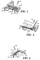
- Fig. 2 is a perspective illustration of a throat plate for the sewing machine, showing the overlock chain stitch drawn by a stream of air into the hollow chaining tongue.
- Fig. 3 is a perspective illustration of the throat plate, similar to Fig. 2, but showing the work product as it moves across the throat plate and receives the overlock stitch and begins to pull the leading thread chain from the chaining tongue.
- Fig. 4 is a perspective illustration of a small portion of the work product, showing schematically how the overlock stitch surrounds both the edge of the work product and the chaining tongue.
- Fig. 5 is a perspective illustration of the throat plate, showing how the thread cutter and thread trimmer and photoelectric detector function to cut and trim the thread chain extending from the previously sewn work product.
- Fig. 6 is a schematic illustration of the vacuum canister and its air control valves.
- Fig. 7 is a detail illustration of the interior valve of the vacuum canister.
- Fig. 8 is a partial perspective illustration of the upper gripper and lower gripper, showing how the anvils oppose the pickers during the picking function.
- Figs. 9-14 are progressive schematic illustrations of the grippers, showing how the grippers grip and open one end of the garment part and hold the garment part as it is everted.
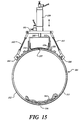
- Figs. 15 and 16 are progressive illustrations of the air induction everter tube, showing the work product after it has been everted and as it is dropped when the everter tube is opened.
- Fig. 17 is a perspective illustration of the blower which is used to induce the stream of air through the components of the system.
- Fig. 18 is a perspective illustration, with parts broken away, of a portion of the air induction everter tube, showing its filter.
- Fig. 19 is a timing diagram which shows the sequence and duration of operation of the elements of the system.
- FIG. 1 illustrates the garment forming and everting system 10 which includes a sewing machine 11 mounted to a work table 12, a conveyor system 14, a transfer conveyor 15 and an everter system 16.
- a photoelectric detector 17 is mounted at the sewing machine to detect the movement of the work products 34 through the sewing area 31 of the sewing machine and to actuate the computer control system for the system 10.
- Sewing machine 11 functions to form overlock stitches 38 (Fig 5) in the overlying edges of the work product 34 that has been precut into the proper shape and folded to form a garment sleeve, pant leg or other substantially cylindrical shaped garment part, etc.
- conveyor system 14 moves the work product 34 further along the sewing path 32, away from the sewing machine and out of the way of the next oncoming work product.
- Transfer conveyor 15 (Fig. 1) engages the work product 34 by moving its clamp bar 18 down into engagement with the work product as the conveyor system 14 releases the work product, and the transfer conveyor moves into alignment with the everter system 16. The everter system opens an end of the work product (Figs.
- the sewing machine 11 includes a throat plate 20 that is positioned over feed dogs (not shown) and beneath the presser foot (not shown) in the conventional manner.
- Throat plate 20 includes a chaining tongue 21 that has an open end 22 extending into an open space 24 of the throat plate, and the other end of the chaining tongue communicates with air conduit 25 which, in turn, communicates with a vacuum canister 52 (Fig. 6) which comprises a source of negative air pressure so as to induce a stream of air to flow into the open end 22 of the chaining tongue 21, as indicated by arrow 26.
- Sewing needles such as the upper sewing needle 28 of sewing machine 11, function to form an overlock stitch about the chaining tongue 21 in the conventional manner.
- the sewing machine can comprise a Wilcox and Gibbs or Union Special sewing machine of the type that forms an overlock stitch, otherwise designated as stitch type 504 of the Federal Standard, Stitches, Seams, and Stitchings, Fed. Std. No. 751a.
- the overlock stitch is formed with three threads, one needle thread, one looper thread and one cover thread.
- a thread chain 29 is formed (Fig. 5) by the needles which extends rearwardly from the previously formed work product, and the thread chain will be joined to the oncoming work product.
- the successive work products will be joined by thread chains, unless the thread chains are cut as described in more detail hereinafter. If the thread chain 29 is cut, it forms a trailing thread chain 44 which is attached to the preceding work product 34 and a leading thread chain 43 which will become attached to the next work product.
- Fig. 2 illustrates the leading thread chain 43 which is drawn into the chaining tongue 21 by the stream of air indicated at 26.
- the thread chain 43 is cut from the preceding work product that passed through the sewing area 31 of the sewing machine, having moved along the sewing path as indicated by arrow 32.
- the overlock stitches 38 are formed by the sewing needles 28 about both the side edge 35 of the work product and the chaining tongue 21, and as the work product moves along the sewing path 32, the overlock stitches slip off the distal end of the chaining tongue 21.
- the overlock stitches 38 surround the leading thread chain, capturing the leading thread chain inside the overlock stitches. This forms a "latch back" configuration of the leading thread chain 43, resulting in no tail of thread chain protruding from the leading edge 36 of the work product 34 (Fig. 3).
- thread chain cutter 40 is positioned so as to cut across the sewing path 32, and, if desired, chain trimmer 41 can be employed to cut parallel to the sewing path 32.
- Thread chain cutter 40 includes a scissors type cutting mechanism of conventional design, with the cutter being placed in a position where it will straddle and therefore cut the trailing thread chain 29 which is attached to the edge 45 of the work product 34. This forms the trailing thread chain 44 and the leading thread chain 43.
- Thread chain trimmer 41 includes an air exhaust conduit 46 positioned adjacent a thread chain cutter 47. The air drawn into the air exhaust conduit 46 draws the trailing thread chain 44 laterally into the bite of the thread chain cutter 47, so that most of the trailing thread chain 44 is cut away from the work product 34.
- the conveyor system 14 (Fig. 1) operates to move the work product 34 along the sewing path 32 first at a rate equal to the rate of stitch formation at the sewing area 31, and later at a faster rate.
- Photoelectric detector 17 is positioned along the sewing path 32 so as to detect the trailing edge 45 of the work product 34.
- air is induced to move through the open end 22 of the chaining tongue 21, the conveyor system 14 is accelerated so as to stretch the thread chain 29 extending from the trailing edge 45 of the previously sewn work product back to the chaining tongue 21 and the needles 28 (Fig.
- the sewing machine operation is continued for a short duration, of between two and five stitches for some work products, so that the proximal end of the leading thread chain surrounds the chaining tongue 21, and thread chain cutter 40 is operated to sever the now taut thread chain so as to form the trailing thread chain 44 and a leading thread chain 43.
- vacuum canister 52 is arranged to induce the flow of air into the open end 22 of the chaining tongue 21 of the throat plate 20.
- Vacuum canister 52 includes a cylindrical housing 54 having a bottom wall and a cylindrical side wall, and a lid 55.
- a Venturi air flow inducer 56 is mounted to lid 55, and air pressure conduit 58 supplies a high velocity stream of air through the Venturi 56, and high velocity stream of air is controlled by control valve 59.
- Air inlet conduit 60 is attached to the Venturi 56 and communicates through lid 55 with the chamber defined by cylindrical housing 54.
- Internal air control valve 64 includes a C-shaped mounting bracket 65 which is suspended from lid 55 internally of the vacuum canister 52.
- Pneumatic cylinder 66 is supported by the bracket 65 and its cylinder rod 68 moves toward and away from valve seat 69 formed at the end of air conduit 25.
- Air conduit 25 extends through lid 55 and terminates at the valve seat 69 which faces the valve element 70 (Fig. 7) that is carried by the cylinder rod 68.
- Valve element 70 is arranged to protrude into and seal against the valve seat 69, so as to close the air conduit 25.
- Control valve 64 Internal air control valve 64 is controlled by the photoelectric detector 17 which detects the movement of the trailing edge 45 of the work product 34 moving away from the sewing area 31 of the sewing machine.
- Control valve 59 which controls the suction applied by the Venturi 56 to the vacuum canister 52 is an on-off valve and is opened to begin the evacuation of the canister 52. Typically, the valve 59 will remain open continuously during the operation of the sewing machine and its associated components so as to draw the pressure in the canister 52 down to a relatively constant desired pressure.
- the internal air control valve 64 will be opened and closed for short durations, on each cycle of the sewing machine, whereas the Venturi will function continuously to continuously draw air from the vacuum canister 52.
- the internal volume of vacuum canister 52 is at least 400 cubic inches, therefore creating a vacuum plenum having a capacity to exert a rapid and aggressive stream of air through the chaining tongue 21 for short durations.
- the conveyor system 14 includes main conveyor 75 and tilt conveyor 76.
- Main conveyor 75 includes an inverted U-shaped conveyor housing 78 mounted to parallel support arms 79 and 80 which are suspended above the work table 12.
- Support arms 79 and 80 are mounted to a support bar 81, with the support bar being supported from work table 12 by support blocks 82.
- Pneumatic cylinders 84 and 85 are mounted beneath the work table 12, with the cylinder rods 86 and 87 connected to the support arms 79 and 80.
- the cylinders 84 and 85 rock the support arms 79 and 80 so as to lift and lower the conveyor housing 78 upwardly away from or downwardly toward engagement with the work table 12, as depicted by arrows 93.
- Continuous conveyor belt 90 is mounted over belt rollers 91 and 92 at opposite ends of the conveyor housing 78, and drive motor 94 is mounted to support arm 80 and is arranged to drive belt roller 91 through a drive belt arrangement 95.
- Tilt conveyor 76 is positioned adjacent sewing machine 11 and includes a support arm 98 that is pivotably mounted to conveyor housing 78 by pivot pin 99, with pivot pin 99 being coaxial with the belt roller 92 of main conveyor 75.
- Endless conveyor belt 100 is mounted on conveyor sheaves 96 and 97, with one conveyor sheave 97 adjacent sewing machine 11 and the other conveyor sheave 96 positioned inside conveyor housing 78 of main conveyor 75 and rotatable about an axis that is coaxial with the pivot pin 99 and the axis of rotation of belt roller 92 of main conveyor 75.
- Conveyor belt 100 is driven in unison with conveyor belt 90 by motor 94.
- Tilt cylinder 102 is mounted on top of main conveyor housing 78, and its cylinder rod 104 is connected to support arm 98 of tilt conveyor 76.
- Tilt cylinder 102 functions to lift the tilt conveyor upwardly away from the work table 12 when the sewing machine operator desires to remove the tilt conveyor from the vicinity of the sewing machine. Further, tilt cylinder 102 functions to raise and lower the tilt conveyor 76 as the main conveyor 75 is lowered and raised from the work table 12, therefore assuring that the tilt conveyor 76 can always be in engagement with a work product adjacent the sewing machine regardless of the position of the main conveyor 75.
- everter system 16 is positioned adjacent an edge 105 of work table 12 and includes an everter tube assembly 106 and gripper assembly 108.
- Lower gripper 109 (Figs. 9-14) is mounted below the work table 12 so that its upper surfaces are flush with the upper surfaces of the work table 12, and lower gripper 109 can be mounted in a notch 111 formed at the edge 105 of the work table, so that work products can be slid across the lower gripper 109 without obstruction.
- Upper gripper 110 is mounted on a telescoping support assembly 114 which includes an upright support leg 115 and an L-shaped support arm 116 having an upright section 118 that is telescopically received in upright support leg 115 and a horizontal section 119 that extends over work table 12, to support upper gripper 110.
- Pneumatic cylinder 117 is arranged to raise and lower L-shaped support arm 116 and upper gripper 110, so that upper gripper 110 can be lowered toward engagement with lower gripper 109, and the two grippers can then grip adjacent plies of the work product, so as to spread or "open" the plies, as will be described in more detail hereinafter.
- lower and upper grippers 109 and 110 are duplicates of each other, and each includes a support bar 120, with pickers 121 and anvils 122 mounted to the support bar and extending toward the opposite gripper.
- Pickers 121 are of conventional design, as disclosed by U.S. patent 4,645,193, and are available from Robotic Systems and Components of Whitinsville, Massachusetts.
- the pickers 121 each include a pair of opposed picking fingers 123 that are spring biased toward one another, and a plunger 124 that reciprocates under the influence of its pneumatic cylinder between and out from between the sloped end portions of the picking fingers 123 so as to alternately wedge the picking fingers apart and then to permit the picking fingers to move under the influence of their spring tension toward each other, so that the picking fingers will grasp and "pick" a ply of material away from an adjacent ply of material.
- the anvils 122 of the lower gripper 109 are placed in alignment with the pickers 121 of the upper gripper, whereas the anvils 122 of the upper gripper are placed in alignment with the pickers 121 of the lower gripper.
- the anvils of the grippers provide a firm surface against which the pickers of the opposite gripper can bear, so as to grasp a ply of material positioned between the grippers.
- Grippers 109 and 110 also each include jaws 126 which have a pair of clamping plates 127 movable toward and away from each about the distal ends of the pickers 121 and anvils 122, with at least one edge 128 of a pair of clamping plates including teeth 128.
- Pneumatic cylinders 129 are mounted in positions to operatively engage the jaws 126, causing the clamping plates to move toward and away from each other.
- transfer conveyor 15 includes a horizontally oriented transfer arm 136 which is suspended above work table 12 by being mounted at one end to upright pivotal support bar 138.
- Pneumatic cylinder 139 positioned below the work table 12 functions through its linkage 140 to oscillate the support bar 138 and the transfer arm 136 as indicated by double headed arrow 141, between a position where transfer arm 136 is substantially parallel to main conveyor 75 and a position coextensive with everter tube assembly 106.
- Clamp bar 18 is supported at the distal end of transfer arm 136 by means of pneumatic cylinder 142 and the cylinder rod 144.
- Guide pin 145 is rigidly mounted to the upper surface of clamp bar 18 and telescopes through an opening 146 of the transfer arm 136.
- guide pin 145 always maintains clamp bar 118 parallel to transfer arm 136 as cylinder 142 moves the clamp bar 18 upwardly away from and downwardly toward engagement with a work product 34 on the work table 12.
- cylinder 142 moves the clamp bar downwardly into engagement with the work product 34
- cylinder 139 pivots the transfer arm 136 and clamp bar 18 to a position in alignment with everter tube assembly 106, which slides the work product 34 on the surface of the work table 12 to the position where it is aligned with the everter system 16.
- everter tube assembly 106 comprises support frame 150, horizontally extending inverted U-shaped support channel 151 supported at its upper surface by support frame 150, and tube halves 152 and 153 each mounted along its upper edge by a hinge assembly 155 to opposite edges of support channel 151 (Fig. 15).
- tube halves 152 and 153 are semi-cylindrical and define lower and upper openable seams 156 and 157, with the hinge assemblies 155 straddling the upper openable seam 157.
- Flexible strip 158 is positioned in the inverted U-shaped channel 151 and is formed in a U-shape and its lower span extends over the upper openable seam 157 so as to seal the seam when a vacuum is drawn within the everter tube.
- Pneumatic cylinder 159 has its cylinder rod 160 mounted to the stationary support channel 151, so that when cylinder rod 160 distends, the cylinder is lifted upwardly away from support plate 151.
- Cross arm 161 is rigidly mounted to cylinder 159 and is movable vertically with cylinder 159, and links 162 and 163 are pivotally connected at their upper ends to the ends of cross arm 161.
- the lower ends of links 162 and 163 are connected by brackets 164 and 165 to the outer surfaces of the semi-cylindrical tube halves 152 and 153.
- the one end of the everter tube assembly 106 is located immediately adjacent work table 12 and the lower and upper grippers 109 and 110, whereas the other end is positioned remotely from the work table 12 and is aligned with a conduit 172 of similar size and shape as the everter tube assembly when in its closed configuration (Fig. 18).
- Conduit 172 is supported by support channel 151 in a stationary position, and flexible conduit 174 extends from conduit 172 to blower assembly 175 (Fig. 17).
- Blower assembly 175 includes a centrifugal blower 176 having an air exhaust duct 178 which exhausts to a filter (not shown), and a centrally located air inlet (not shown).
- Air plenum 179 is mounted about the air inlet and includes lateral air valve 181.
- Air valve 181 includes a valve housing 182, valve plate 184, valve cylinder 185 and flexible conduit 174 mounted to the valve plate 184. When cylinder 185 is extended, valve plate 184 slides laterally of the valve housing 182 so that an opening is formed through the valve housing, thereby permitting the movement of air from the everter tube assembly 106, through flexible air induction conduit 174, through air valve 181, through air plenum 179 and into the inlet of blower 176. When valve plate 184 is returned by cylinder 185 it closes the valve 182 and cuts off the stream of air moving from the everter tube.
- a filter screen 191 (Fig. 18) is mounted to cylindrical conduit 172, in the path of the air stream moving from everter tube assembly 106 to the blower.
- upper gripper 110 moves down toward the work product 34 so that both the lower and upper grippers make positive contact with the work product 34.
- the pickers 121 of both the lower and upper grippers open by the plungers 124 (Fig. 8) of the cylinders of the pickers protruding further between the picking fingers 123. This causes the picking fingers to move apart. This allows the picking fingers 123 be open while in contact with the lower and upper plies of the work piece 34. While the pickers are still in contact with the work piece, the plungers 124 retract, thereby allowing the spring urged picking fingers 123 to move toward each other.
- This movement toward each other of the picking fingers allows the teeth of the picking fingers to grasp the nap of the material, so that one ply of the material is picked away from the other ply.
- This picking function is assisted by the presence of the flat surfaces of the anvils 127 opposite each picking finger, to assure that a firm grip is applied by the pickers to the nap of the material.
- valve 181 at the centrifugal blower 176 (Fig. 17) is closed, thereby terminating the air stream 190 into the everter conduit 106, allowing the work product to collapse in the everter conduit 106 (Fig. 15), and the pickers and jaws of the grippers 109 and 110 are opened, thereby releasing the work product.
- the now everted work product 134 is allowed to drop from the everter 106 by cylinder 159 opening the everter conduit 106 (Fig. 16), whereupon the work product 34 is dropped to an awaiting surface conveyor, container, etc.
- Fig. 24 is a timing diagram which illustrates the sequence and duration of the steps of the process.
Claims (11)
- Verfahren zum Ausbilden schlauchförmiger Bekleidungsstücke (34), mit den Schritten Vorschieben von Abschnitten aus Bekleidungsmaterial in einer zusammengefalteten Anordnung mit oberen und unteren Lagen, die jeweils eine ungenähte Außenkante (35) aufweisen, der Reihe nach durch eine Nähmaschine (11) und Bilden von Nähten (38) durch einen Bereich der ungenähten Außenkanten (35) der oberen und der unteren Lagen der Abschnitte, um schlauchförmige Bekleidungsstücke (34) mit mindestens einem offenen Ende auszubilden, deren Inneres nach außen gekehrt ist, gekennzeichnet durch:Entfernen jedes Bekleidungsstücks der Reihe nach von der Nähmaschine (11) und aus dem Weg eines nachfolgend ankommenden Abschnitts (34) aus Bekleidungsmaterial;Öffnen der unteren und der oberen Lage jedes Bekleidungsstücks (34) an dem mindestens einen offenen Ende des Bekleidungsstücks (34);Erzeugen eines Luftunterdrucks zwischen den geöffneten unteren und oberen Lagen jedes Bekleidungsstücks (34) und an dem mindestens einen offenen Ende, um das Bekleidungsstück (34) zu wenden; undFreigeben jedes gewendeten Bekleidungsstücks (34), um es zu einer Ansammlung von zuvor gewendeten Bekleidungsstücken (34) zu bringen.
- Verfahren zum Ausbilden schlauchförmiger Bekleidungsstücke (34) nach Anspruch 1, wobei der Schritt Bilden der Nähte (38) durch die oberen und die unteren Lagen der Abschnitte aus Bekleidungsmaterial gekennzeichnet ist durch Bilden einer überwendlichen Naht (38) entlang der aufeinander ausgerichteten Außenkanten (35) des Bekleidungsmaterials um eine hohle Kettenzunge (21), wobei sich eine Fadenkette (29) von der Hinterkante (45) jedes Bekleidungsstücks (34) zurück zu den Nadeln (28) der Nähmaschine (11) erstreckt, und wobei weiterhin die Schritte vorgesehen sind Durchtrennen der Fadenkette (29) und Einziehen des abgetrennten Endes (43) der Fadenkette (29) an den Nadeln (28) der Nähmaschine (11) in die hohle Kettenzunge (21) der Nähmaschine (11).
- Verfahren zum Ausbilden schlauchförmiger Bekleidungsstücke (34) nach Anspruch 1, wobei der Schritt Entfernen der Bekleidungsstücke (34) von der Nähmaschine (11) gekennzeichnet ist durch Ausrichten eines Endes jedes Bekleidungsstücks (34) auf einen Endbereich einer röhrenförmigen Leitung (106); und wobei der Schritt Öffnen der unteren und der oberen Lage des Bekleidungsstücks (34) an einem Ende des Bekleidungsstücks (34) gekennzeichnet ist durch Öffnen des Endes des Bekleidungsstücks (34), das dem Endbereich der röhrenförmigen Leitung (106) benachbart ist; und wobei der Schritt Erzeugen eines Luftunterdrucks zwischen den geöffneten unteren und oberen Lagen gekennzeichnet ist durch Einblasen eines Luftstroms (190), so daß er durch die röhrenförmige Leitung (106) strömt.
- Verfahren zum Ausbilden schlauchförmiger Bekleidungsstücke (34) nach Anspruch 3, wobei der Schritt Freigeben des Bekleidungsstücks (34) gekennzeichnet ist durch Öffnen der röhrenförmigen Leitung (106) ihrer Länge nach und Abwerfen des Bekleidungsstücks (34) durch die Öffnung.
- Verfahren zum Ausbilden schlauchförmiger Bekleidungsstücke (34) nach Anspruch 1, wobei der Schritt Entfernen der Bekleidungsstücke von der Nähmaschine (11) gekennzeichnet ist durch Verschieben des Bekleidungsstücks (34) über die Oberfläche eines Arbeitstisches (12) aus einer der Nähmaschine (11) benachbarten Position in eine Position mit Ausrichtung auf einen ersten Endbereich einer Wenderöhre (106), die einen ersten und einen zweiten Endbereich aufweist; und wobei der Schritt Öffnen der unteren und der oberen Lage des Bekleidungsstücks (34) an dem mindestens einen offenen Ende des Bekleidungsstücks (34) gekennzeichnet ist durch Ausrichten des mindestens einen offenen Endes des Bekleidungsstücks (34) auf den ersten Endbereich der Wenderöhre (106); und wobei der Schritt Erzeugen eines Luftunterdrucks zwischen der unteren und der oberen Lage gekennzeichnet ist durch Abziehen von Luft von dem anderen Ende der Wenderöhre (106).
- Vorrichtung zum Ausbilden schlauchförmiger Bekleidungsstücke (34), mit einem Fördermittel (75) zum Vorschieben eines Abschnitts aus Bekleidungsmaterial in einer zusammengefalteten Anordnung mit oberer und unterer Lage, die jeweils eine ungenähte Außenkante (35) aufweist, durch die Nähmaschine (11) zum Bilden von Nähten (38) durch einen Bereich der ungenähten Außenkanten (35) der oberen und der unteren Lagen des Bekleidungsmaterials, um ein schlauchförmiges Bekleidungsstück (34) mit mindestens einem offenen Ende auszubilden, mit einer Wenderöhrenanordnung (106) und mit Mitteln zum Entfernen des Bekleidungsstücks von der Nähmaschine (11) und aus dem Weg eines nachfolgend ankommenden Abschnitts aus Bekleidungsmaterial, wobei das offenen Ende des Bekleidungsstücks (34) in Ausrichtung auf die Wenderöhrenanordnung (106) angeordnet wird, gekennzeichnet durchGreifmittel (109, 110) zum Trennen der oberen und der unteren Lage des Bekleidungsstücks (34) an dem offenen Ende des Bekleidungsstücks (34) an einer der Wenderöhrenanordnung (106) benachbarten Stelle;Mittel (175) zum Einblasen eines Luftstroms (190), so daß er zwischen den getrennten unteren und oberen Lagen, durch das offenen Ende des Bekleidungsstücks (34) und in die Wenderöhrenanordnung (106) in einer das Bekleidungsstück wendenden Richtung strömt; undMittel zum Freigeben des Bekleidungsstücks (34) aus der Wenderöhrenanordnung (106), um es zu einer Ansammlung von zuvor gewendeten Bekleidungsstücken (34) zu bringen.
- Vorrichtung zum Ausbilden schlauchförmiger Bekleidungsstücke (34) nach Anspruch 6, wobei die Nähmaschine gekennzeichnet ist durch eine überwendlich nähende Nähmaschine (11) mit einer hohlen Kettenzunge (21) zum Bilden überwendlicher Nähte (38) durch die oberen und die unteren Lagen des Bekleidungsmaterials entlang der aufeinander ausgerichteten Kanten (35) des Bekleidungsmaterials, wobei sich eine Fadenkette (29) von der Hinterkante (45) jedes Bekleidungsstücks (34) zurück zu den Nadeln (28) der Nähmaschine (11) erstreckt; durch Mittel zum Spannen der Fadenkette (29); durch einen Fadenkettendurchtrenner (41) zum Durchtrennen der Fadenkette (29), wenn die Fadenkette (29) gespannt ist, und durch Mittel zum Einziehen der abgetrennten Enden (43) der Fadenkette (29) an den Nadeln (28) der Nähmaschine (11) in die hohle Kettenzunge (21) der Nähmaschine (11).
- Vorrichtung zum Ausbilden schlauchförmiger Bekleidungsstücke (34) nach Anspruch 6, wobei die Mittel zum Entfernen des Bekleidungsstücks (34) von der Nähmaschine (11) gekennzeichnet sind durch Ausrichten eines Endes des Bekleidungsstücks (34) auf einen Endbereich einer röhrenförmigen Leitung (106); und wobei die Greifmittel (109, 110) zum Öffnen der unteren und der oberen Lage des Bekleidungsstücks (34) an einem Ende des Bekleidungsstücks gekennzeichnet sind durch einen oberen Greifer (110) und einen unteren Greifer (109), wobei jeder der Greifer (109, 110) Zupfer (121) zum Trennen der Lagen des Materials des Bekleidungsstücks, Klemmplatten (127) zum Greifen der Lagen des Materials nach der Trennung durch die Zupfer (121) und Mittel (114, 117) zum Auseinanderbewegen des oberen und des unteren Greifers (110, 109) zwecks Öffnen des Bekleidungsstücks (34) aufweist.
- Vorrichtung zum Ausbilden schlauchförmiger Bekleidungsstücke (34) nach Anspruch 8, wobei die Wenderöhrenanordnung (106) gekennzeichnet sind durch eine gestreckte Röhre, die von halbzylindrischen Röhrensegmenten (152, 153) ausgebildet wird, und wobei das Mittel zum Freigeben des Bekleidungsstücks (34) Mittel (159) zum Öffnen der Röhrensegmente (152, 153) voneinander weg und zum Abwerfen des Bekleidungsstücks (34) durch die Öffnung aufweist.
- Vorrichtung zum Ausbilden schlauchförmiger Bekleidungsstücke (34) nach Anspruch 6, wobei die Mittel zum Entfernen des Bekleidungsstücks (34) von der Nähmaschine (11) gekennzeichnet sind durch einen Klemmbalken (18) zum Angreifen an dem Bekleidungsstück (34) und zum Verschieben des Bekleidungsstücks (34) über die Oberfläche eines Arbeitstisches (12) aus einer der Nähmaschine (11) benachbarten Position in eine Position mit Ausrichtung auf einen Endbereich der Wenderöhrenanordnung (106).
- Vorrichtung zum Ausbilden schlauchförmiger Bekleidungsstücke nach Anspruch 8, wobei der obere und der untere Greifer (110, 109) jeweils gekennzeichnet sind durch Finger (123), die sich aufeinander zu und voneinander weg bewegen, um ein Bekleidungsstück (34) zu ergreifen.
Applications Claiming Priority (3)
| Application Number | Priority Date | Filing Date | Title |
|---|---|---|---|
| US678641 | 1984-12-06 | ||
| US07/678,641 US5134947A (en) | 1990-12-20 | 1991-04-01 | Method and apparatus for forming and everting a work product |
| PCT/US1992/002192 WO1992017631A1 (en) | 1991-04-01 | 1992-03-13 | Method and apparatus for forming and everting a work product |
Publications (3)
| Publication Number | Publication Date |
|---|---|
| EP0537323A1 EP0537323A1 (de) | 1993-04-21 |
| EP0537323A4 EP0537323A4 (de) | 1994-02-23 |
| EP0537323B1 true EP0537323B1 (de) | 1997-05-28 |
Family
ID=24723666
Family Applications (1)
| Application Number | Title | Priority Date | Filing Date |
|---|---|---|---|
| EP92910104A Expired - Lifetime EP0537323B1 (de) | 1991-04-01 | 1992-03-13 | Verfahren und vorrichtung zum herstellen und umdrehen eines werkstückes |
Country Status (7)
| Country | Link |
|---|---|
| US (1) | US5134947A (de) |
| EP (1) | EP0537323B1 (de) |
| JP (1) | JPH05508095A (de) |
| AT (1) | ATE153715T1 (de) |
| CA (1) | CA2084055A1 (de) |
| DE (1) | DE69219984T2 (de) |
| WO (1) | WO1992017631A1 (de) |
Families Citing this family (4)
| Publication number | Priority date | Publication date | Assignee | Title |
|---|---|---|---|---|
| DE19543682A1 (de) * | 1994-12-09 | 1996-06-13 | Phoenix Ag | Verfahren zum Wenden und Endausformen von aufblasbaren Körpern |
| US6834603B1 (en) * | 2002-03-05 | 2004-12-28 | Atlanta Attachment Company | Attachment gusset with ruffled corners and system for automated manufacture of same |
| US7100525B1 (en) | 2003-02-10 | 2006-09-05 | Atlanta Attachment Company, Inc. | System and method of finishing ruffled gussets/borders |
| US7984681B1 (en) | 2007-11-20 | 2011-07-26 | Atlanta Attachment Company | Automatic panel sewing and flanging system |
Family Cites Families (5)
| Publication number | Priority date | Publication date | Assignee | Title |
|---|---|---|---|---|
| US3577942A (en) * | 1969-07-30 | 1971-05-11 | Sliver Knit Hosiery Mills Inc | Apparatus for closing hosiery toes and everting hosiery and method |
| US3568898A (en) * | 1969-09-05 | 1971-03-09 | Roy J Griffin Jr | Everting apparatus and method |
| IT1027837B (it) * | 1974-12-19 | 1978-12-20 | Sperotto Spa Giuseppe | Apparecchiatura per rovesciare tessuti in forma tubolare |
| IT1161110B (it) * | 1983-03-11 | 1987-03-11 | Fabio Selvi | Macchine 'transfer' per il rovesciamento di un elemento tessile tubolare, la cucitura di una estremita' rovesciata e successivo rirovesciamento e scarico de medesimo |
| US5031551A (en) * | 1990-08-03 | 1991-07-16 | Graham Donell I | Sewing machine attachments |
-
1991
- 1991-04-01 US US07/678,641 patent/US5134947A/en not_active Expired - Fee Related
-
1992
- 1992-03-13 WO PCT/US1992/002192 patent/WO1992017631A1/en active IP Right Grant
- 1992-03-13 AT AT92910104T patent/ATE153715T1/de not_active IP Right Cessation
- 1992-03-13 CA CA002084055A patent/CA2084055A1/en not_active Abandoned
- 1992-03-13 JP JP92509354A patent/JPH05508095A/ja active Pending
- 1992-03-13 EP EP92910104A patent/EP0537323B1/de not_active Expired - Lifetime
- 1992-03-13 DE DE69219984T patent/DE69219984T2/de not_active Expired - Fee Related
Also Published As
| Publication number | Publication date |
|---|---|
| US5134947A (en) | 1992-08-04 |
| DE69219984D1 (de) | 1997-07-03 |
| EP0537323A4 (de) | 1994-02-23 |
| CA2084055A1 (en) | 1992-10-02 |
| WO1992017631A1 (en) | 1992-10-15 |
| EP0537323A1 (de) | 1993-04-21 |
| ATE153715T1 (de) | 1997-06-15 |
| DE69219984T2 (de) | 1997-11-06 |
| JPH05508095A (ja) | 1993-11-18 |
Similar Documents
| Publication | Publication Date | Title |
|---|---|---|
| EP0687758B1 (de) | Vorrichtung zum Entfernen von Falten aus Schlauchwarenrohlingen auf einem Träger | |
| US5865135A (en) | Method and apparatus for producing a hemmed folded and seamed finished workpiece | |
| US5915319A (en) | Method and apparatus for producing a hemmed, folded, and seamed finished workpiece | |
| GB2248544A (en) | Workpiece folding device | |
| JP2969489B2 (ja) | 袖口自動縫製装置 | |
| US4292908A (en) | Hemmer-seamer | |
| JPH09108467A (ja) | シャツ胴体への袖の縫い付けワークステーション並びにその方法並びにそのためのミシン | |
| GB2216549A (en) | Improvements relating to sewing | |
| US4903621A (en) | Hosiery toe closing method and apparatus | |
| US5562060A (en) | Waist band attachment system | |
| US5522332A (en) | Waist band attachment system | |
| EP0159507B1 (de) | Vorrichtung, um ein langes Werkstück aus dem Nähpunkt herauszuziehen | |
| EP0537323B1 (de) | Verfahren und vorrichtung zum herstellen und umdrehen eines werkstückes | |
| JPH0312909B2 (de) | ||
| US4538534A (en) | Apparatus and method for processing hosiery blanks | |
| EP0516842B1 (de) | Nähmaschine mit automatischer hefteinrichtung | |
| CZ20022501A3 (cs) | Způsob pletení hadicového úpletového výrobku, zařízení pro výrobu hadicových úpletových výrobků s koncovými ąpičkami, a způsob seąívání koncového okraje hadicového úpletu | |
| US5653431A (en) | Fabric piece handling system | |
| US5203270A (en) | Sewing machine with latch back device | |
| JPH03168178A (ja) | テープ付け空環縫込み装置 | |
| EP0132486B1 (de) | Verfahren für das automatische Nähen von Reissverschlüssen und automatische Nähmaschine dafür | |
| EP1464748A2 (de) | Verfahren und Vorrichtung zum Beschicken von Strümpfen zur Transporteinrichtung einer Nähmaschine | |
| JPH024316B2 (de) |
Legal Events
| Date | Code | Title | Description |
|---|---|---|---|
| PUAI | Public reference made under article 153(3) epc to a published international application that has entered the european phase |
Free format text: ORIGINAL CODE: 0009012 |
|
| AK | Designated contracting states |
Kind code of ref document: A1 Designated state(s): AT DE FR GB IT |
|
| 17P | Request for examination filed |
Effective date: 19930225 |
|
| A4 | Supplementary search report drawn up and despatched |
Effective date: 19940106 |
|
| AK | Designated contracting states |
Kind code of ref document: A4 Designated state(s): AT DE FR GB IT |
|
| 17Q | First examination report despatched |
Effective date: 19950828 |
|
| GRAG | Despatch of communication of intention to grant |
Free format text: ORIGINAL CODE: EPIDOS AGRA |
|
| GRAH | Despatch of communication of intention to grant a patent |
Free format text: ORIGINAL CODE: EPIDOS IGRA |
|
| GRAH | Despatch of communication of intention to grant a patent |
Free format text: ORIGINAL CODE: EPIDOS IGRA |
|
| ITF | It: translation for a ep patent filed |
Owner name: DE DOMINICIS & MAYER S.R.L. |
|
| GRAA | (expected) grant |
Free format text: ORIGINAL CODE: 0009210 |
|
| AK | Designated contracting states |
Kind code of ref document: B1 Designated state(s): AT DE FR GB IT |
|
| REF | Corresponds to: |
Ref document number: 153715 Country of ref document: AT Date of ref document: 19970615 Kind code of ref document: T |
|
| REF | Corresponds to: |
Ref document number: 69219984 Country of ref document: DE Date of ref document: 19970703 |
|
| ET | Fr: translation filed | ||
| PLBE | No opposition filed within time limit |
Free format text: ORIGINAL CODE: 0009261 |
|
| STAA | Information on the status of an ep patent application or granted ep patent |
Free format text: STATUS: NO OPPOSITION FILED WITHIN TIME LIMIT |
|
| 26N | No opposition filed | ||
| PGFP | Annual fee paid to national office [announced via postgrant information from national office to epo] |
Ref country code: FR Payment date: 19990218 Year of fee payment: 8 |
|
| PGFP | Annual fee paid to national office [announced via postgrant information from national office to epo] |
Ref country code: AT Payment date: 19990219 Year of fee payment: 8 Ref country code: GB Payment date: 19990219 Year of fee payment: 8 Ref country code: DE Payment date: 19990219 Year of fee payment: 8 |
|
| PG25 | Lapsed in a contracting state [announced via postgrant information from national office to epo] |
Ref country code: GB Free format text: LAPSE BECAUSE OF NON-PAYMENT OF DUE FEES Effective date: 20000313 Ref country code: AT Free format text: LAPSE BECAUSE OF NON-PAYMENT OF DUE FEES Effective date: 20000313 |
|
| GBPC | Gb: european patent ceased through non-payment of renewal fee |
Effective date: 20000313 |
|
| PG25 | Lapsed in a contracting state [announced via postgrant information from national office to epo] |
Ref country code: FR Free format text: LAPSE BECAUSE OF NON-PAYMENT OF DUE FEES Effective date: 20001130 |
|
| REG | Reference to a national code |
Ref country code: FR Ref legal event code: ST |
|
| PG25 | Lapsed in a contracting state [announced via postgrant information from national office to epo] |
Ref country code: DE Free format text: LAPSE BECAUSE OF NON-PAYMENT OF DUE FEES Effective date: 20010103 |
|
| PG25 | Lapsed in a contracting state [announced via postgrant information from national office to epo] |
Ref country code: IT Free format text: LAPSE BECAUSE OF NON-PAYMENT OF DUE FEES;WARNING: LAPSES OF ITALIAN PATENTS WITH EFFECTIVE DATE BEFORE 2007 MAY HAVE OCCURRED AT ANY TIME BEFORE 2007. THE CORRECT EFFECTIVE DATE MAY BE DIFFERENT FROM THE ONE RECORDED. Effective date: 20050313 |