EP0536735B1 - Tetraaxialgewebe und Webstuhl zum Herstellen davon - Google Patents
Tetraaxialgewebe und Webstuhl zum Herstellen davon Download PDFInfo
- Publication number
- EP0536735B1 EP0536735B1 EP92117143A EP92117143A EP0536735B1 EP 0536735 B1 EP0536735 B1 EP 0536735B1 EP 92117143 A EP92117143 A EP 92117143A EP 92117143 A EP92117143 A EP 92117143A EP 0536735 B1 EP0536735 B1 EP 0536735B1
- Authority
- EP
- European Patent Office
- Prior art keywords
- yarns
- bias
- warp yarns
- warp
- course
- Prior art date
- Legal status (The legal status is an assumption and is not a legal conclusion. Google has not performed a legal analysis and makes no representation as to the accuracy of the status listed.)
- Expired - Lifetime
Links
Images


Classifications
-
- D—TEXTILES; PAPER
- D03—WEAVING
- D03D—WOVEN FABRICS; METHODS OF WEAVING; LOOMS
- D03D13/00—Woven fabrics characterised by the special disposition of the warp or weft threads, e.g. with curved weft threads, with discontinuous warp threads, with diagonal warp or weft
- D03D13/002—With diagonal warps or wefts
-
- D—TEXTILES; PAPER
- D03—WEAVING
- D03D—WOVEN FABRICS; METHODS OF WEAVING; LOOMS
- D03D41/00—Looms not otherwise provided for, e.g. for weaving chenille yarn; Details peculiar to these looms
-
- D—TEXTILES; PAPER
- D03—WEAVING
- D03D—WOVEN FABRICS; METHODS OF WEAVING; LOOMS
- D03D41/00—Looms not otherwise provided for, e.g. for weaving chenille yarn; Details peculiar to these looms
- D03D41/007—Vertical looms
-
- Y—GENERAL TAGGING OF NEW TECHNOLOGICAL DEVELOPMENTS; GENERAL TAGGING OF CROSS-SECTIONAL TECHNOLOGIES SPANNING OVER SEVERAL SECTIONS OF THE IPC; TECHNICAL SUBJECTS COVERED BY FORMER USPC CROSS-REFERENCE ART COLLECTIONS [XRACs] AND DIGESTS
- Y10—TECHNICAL SUBJECTS COVERED BY FORMER USPC
- Y10S—TECHNICAL SUBJECTS COVERED BY FORMER USPC CROSS-REFERENCE ART COLLECTIONS [XRACs] AND DIGESTS
- Y10S139/00—Textiles: weaving
- Y10S139/01—Bias fabric digest
Definitions
- This invention relates to a tetraxial fabric and a weaving machine for the manufacture thereof.
- tetraxial fabric composed or warp yarns, weft yarns, first bias yarns and second bias yarns which crisscross each other, as well as the warp and weft yarns, along two different diagonal directions.
- Such a fabric structure has nearly the same resistance to stretching in all directions, i.e. exhibits an isotropic behavior.
- a tetraxial fabric as above is known from European Patent Application EP-0263392.
- the weave geometry therein provides for no bonds between yarns, and the yarns are allowed to drift relative to one another into patches of low yarn density and higher yarn density across the fabric. The isotropic behavior and the eveness of the fabric are then bound to be downgraded.
- the disclosed weave can only produce fabrics having a fill coefficient below 50%, which forbids any compact fabric.
- a tetraxial fabric having warp yarns, weft yarns, first bias yarns and second bias yarns crisscrossing each other, and the warp and weft yarns, along two different diagonal directions, beina characterized in that a first course of warp yarns is overlaid by the weft yarns and, in turn, overlies the first and second bias yarns, and that a second course of warp yarns, which alternate to the warp yarns in the first course, overlies the weft yarns and is, in turn, overlaid by the first and the second bias yarns.
- a weaving machine which comprises means for guiding the warp yarns toward a fabric formation area, and means for passing the weft yarns through the shed of warp yarns in said fabric formation area, and further comprises means for guiding the bias yarns in said fabric formation area such that said bias yarns cross each other and the warp and weft yarns according to two different diagonal directions, said means for guiding the warp yarns comprise a first guide member guiding the first course of warp yarns and a second guide member guiding the second course of warp yarns in an offset relationship with respect to the first course of warp yarns, said first and second guide members being disposed at juxtaposed positions to each other, characterized in that each of said first and second guide members being movable between a rearward position where their respective course of warp yarns lie at one side relative to the bias yarns and the other course of warp yarns in the rearward position and a forward position where their respective course of warp yarns lie at the opposite side relative
- the weave in Figure 1 comprises a first set of odd-numbered warp yarns, indicated at A, which form a first course of warp yarns, and a second set of even-numbered warp yarns, indicated at B, which form a second course of warp yarns; all of the above warp yarns A, B lying parallel to one another.
- the weave in Figure 1 further comprises weft yarns lying parallel to one another and being indicated at C where odd-numbered and D where even-numbered.
- the weave comprises a first set of bias yarns lying parallel to one another and being indicated at E, and a second set of bias yarns lying parallel to one another and being indicated at F.
- the warp yarns A, B cross the weft yarns C, D orthogonally.
- the bias yarns E and bias yarns F cross the warp yarns A, B and weft yarns C, D diagonally along two respective diagonal directions having opposite inclinations; in the example shown, the bias yarn sets E, F extend orthogonal to each other at an angle of 45° to the warp yarns A, B and the weft yarns C, D.
- the crossovers of all said yarns locate at common crossover points, that is, at each crossover point there intersect one warp yarn, one weft yarn, one bias yarn from the first set of bias yarns, and one bias yarn from the second set of bias yarns.
- the layout of said yarns is such that the warp yarns A are overlaid by all the weft yarns C,D and, in turn, overlie both the bias yarns E and the bias yarns F, whilst the warp yarns B overlie all the weft yarns C, D and are overlaid by both the bias yarns E and the bias yarns F.
- Such a symmetrical arrangement of the yarns provides a secure bond therebetween effective to prevent undesired relative drifting of the yarns and, therefore, the formation of different density patches across the fabric.
- the fabric will exhibit isotropic behavior under stretch and an even texture.
- This symmetrical arrangement also has the advantage of imposing no limitations on the spacing of the yarns, thereby affording a fill coefficient of up to 100%, i.e. a fabric showing no gaps between yarns.
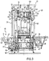
- the machine in Figure 2 intended for manufacturing the fabric of Figure 1, comprises a bearing structure 10 on which the machine components are mounted, in particular means for guiding the warp yarns A, B toward a fabric formation area, means for passing the weft yarns C, D through the shed of the warp yarns A, B in said fabric formation area, and means for guiding the bias yarns E, F toward said fabric formation area.
- the guide means for the warp yarns A, B comprise a first guide member for the warp yarns A and a second guide member for the warp yarns B; these two members are mounted to face each other.
- the guide member for the warp yarns A comprises a holder bar 11 carrying a set of needles 12 parallel to one another.
- Each needle 12 has a hole 13 through which a respective warp yarn A is passed; the warp yarns A passed through the holes 13 extend from a set of reels 14 carried on a creel 15.
- the holder bar 11 is mounted on the ends of two side arms 16 which are connected to a shaft 17 with the other ends.
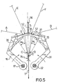
- the bar 11 with the needles 12 is reciprocated rotatively about the shaft 17 to move the holes 13 of the needles 12 between a position G and a position G' shown in Figure 5,
- Power is provided by a main electric motor 18 rotating a shaft 20 through a drive unit 19; the shaft 20, in turn, rotates two wheels 21 mounted thereto; each of the two opposite sides of each wheel 21 is formed with an endless camming groove 22; two levers 23 pivoted with one end on the stationary portion of the machine are provided, at intermediate locations thereon, with two respective pins (of which one is shown at 81 in Figure 4) which engage in two respective grooves 22, each on a respective wheel 21, such that the rotation of the wheels 21 will reciprocate the levers 23 rotatively about their pivot centers; the rotary reciprocation of each lever 23 is transferred to the shaft 17 through a rod 24 and a lever 25, and transmitted from the shaft 17 to the bar 11 through the arms 16.
- the guide member for the warp yarns B is identical of the guide member for the warp yarns A, and accordingly, comprises a holder bar 26 holding a set of parallel needles 27.
- the needles 27 locate in front of the needles 12; additionally, these needles 27 are offset one pitch length from the needles 12.
- Each needle 27 has a hole 28 through which a respective warp yarn B is passed; the warp yarns B passed through the holes 28 extend from a set of reels 29 carried on a creel 30.
- the holder bar 26 is mounted on the ends of two side arms 31 connected, at the other ends, to a shaft 32.
- the bar 26 with the needles 27 is reciprocated rotatively about the shaft 32 such that the holes 28 in the needles 27 are moved between a position H and a position H', shown in Figure 5,
- the bar 26 is reciprocated by means of the wheels 21, like bar 11.
- Two levers 33 are provided here which, similarly to the levers 23, are pivoted with one end on the stationary portion of the machine and provided with two respective pins; these pins engage in two more grooves 22 on the wheels 21 (that is, the two grooves 22 on the other sides of the wheels 21 not engaged by the pins 81 of the levers 23) such that the rotary movement of the wheels 21 will reciprocate the levers 33 rotatively about their pivot centers; the rotary reciprocation of each lever 33 is transferred to the shaft 32 through a rod 34 and a lever 35, and transmitted from the shaft 32 to the bar 26 through the arms 31.
- the insertion means for the weft yarns C, D comprise two conventional telescoping pickers 36, 37 laid side-by-side and parallel to each other; picker 36 will insert tie weft yarn C and picker 37 the weft yarn D.
- the two pickers 36, 37 are conventionally reciprocable linearly between retracted and extended positions, along a direction perpendicular to and underlying the needles 12 and 27; said pickers 36, 37 are driven by the same electric motor 18 which drives the guide means for the warp yarns; specifically, the motor 18 rotates a wheel 38 through drive means not shown; each of the two opposite sides of the wheel 38 is formed with an endless camming groove 39; for picker 37, there is a lever 40, pivoted with one end on the stationary portion of the machine, provided with a pin 41 which engages in either groove 39 such that the rotary motion of the wheel 38 will reciprocate the lever 40 rotatively about its pivot center; this rotary reciprocating motion is transferred, through a rod 42, to a further lever 43, also pi
- a weft yarn C,D feeder unit Located opposite the pickers 36, 37 is a weft yarn C,D feeder unit, generally shown at 46, which feeds the weft yarn C to picker 36 and the weft yarn D to picker 37 in a conventional way.
- the weft yarn C, wound on a spool 47 is passed through an opening 48 and is picked up by the clamping head of the picker 36 with the latter in its fully extended position; as the picker 36, after picking up that yarn, is returned to its retracted position to insert the weft yarn C through the shed of the warp yarns A, B, a cutter mechanism 49 severs the weft yarn at the location of the opening 48, whilst the picker 36 on the opposite side releases the other end of the weft yarn.
- the same action takes place with the weft yarn D, picked up by picker 37; in this case, the weft yarn D is wound on a spool 50, and is severed by a cutter mechanism 51.
- the guide means for the bias yarns E, F comprise a set of guide elements consisting of plates 52 attached to a chain 53, which extend in a plane overlying the needles 12 and 27.
- Each plate 52 has an eyelet 54 through which a respective bias yarn E, F is passed.
- the chain 53 is an endless chain wound around a sprocket wheel 55 rigid with an idler shaft 56, on the one side and around a sprocket wheel 57 rigid with a shaft 58 driven rotatively by a step motor 59 through a shaft 00 and two gear wheels 61, 62, on the other side.
- the chain 53 will entrain the plates 52 stepwise around an elongate endless path having two straight sections and two circular arc sections interconnecting the two straight sections.
- bias yarns going through the eyelets 54 in the plates 52 which locate along the straight section facing the holes 13 of the needles 12 in position G are bias yarns E
- bias yarns going through the eyelets 54 in the plates 52 which locate along the other straight section facing the holes 28 of the needles 27 in position H are bias yarns F.
- a bias yarn E, F feeder unit including a carousel 63 which entrains sets of reels 64 in timed relationship to the movement of the underlying plates 52; a yarn extends from each reel 64 which is then passed through the eyelet 54 in a respective plate 52.
- the carousel 63 includes a set of box-type holder elements 65 on which three reels 64 are carried in a freely rotatable manner.
- the holder elements 65 are rigid with two chains 66 extending in two parallel planes which overlie each other; the chains 66 are wound each around three sprocket wheels 67 fitted on three respective idler shafts 68 and around a sprocket wheel 69 rigid with a shaft 70 driven rotatively by the electric motor 18 through various drives among which are a shaft 71, a drive unit 72, and two cogged pulleys 73, 74 with a cogged drive belt 75 therebetween.
- the path travelled by the chains 66 is substantially lozenge-like with the acute angles of the lozenge located at the circular arc sections of the underlying chain 53; thus, the reels 64 will be entrained by the carousel 63 around said lozenge-like path.
- Shown at Z in Figure 5 is the start position of the fabric formed at a bar 76 to which all the woven yarns are run.
- the formed fabric is denoted by T, and during the process cycle just described, is moved forward by a purposely provided sand roll of conventional design in the direction of the arrow in Figure 5.
- This sand roll moves the fabric T forward of continuous motion at a rate which is suitably timed to the sequential movements reviewed above.
- bias yarns E move stepwise in the right-to-left direction
- yarns F move stepwise in the left-to-right direction while crossing one another.
- Each bias yarn in a set of bias yarns E or F on reaching its respective fabric end, turns around its respective wheel 55 or 57 to the opposite side, thereby becoming the first yarn to be tied in the other set of bias yarns.
- the carousel 63 is moved of continuous motion but in any case appropriate to keep the reels 64 corresponding to the respective eyelets 54 in the plates 52.
- the formed fabric T is pulled by means of the sand roll such that it will move forward a distance equal to the pitch distance between the warp yarns A and the warp yarns B.
- a reed 78 which is effective, once the weft yarn C is inserted, to hold the warp yarns A separated and urge said weft yarn C close against the previously formed fabric; likewise, on the two arms 31, there is mounted a reed 79 which is effective, once the weft yarn D is inserted, to hold the warp yarns B separated and to urge said weft yarn D close against the previously formed fabric.
- the reeds 78, 79 are driven by grooved wheels 80 fast with the shaft 20 and coaxial with the wheels 21; the drive arrangement is similar to that previously reviewed for operating the bar 11 with the needles 12 and the bar 26 with the needles 27 and will not, therefore, be explained in detail here.
- the machine as described and illustrated is simple in construction and effective in operation.
- the particular lozenge-like shape of the carousel 63 path compensates for tension differences as the inclination of the bias yarns E, F changes, especially as such bias yarns move from one straight section to the other of the endless path of the chain 53.
- the inclination of the bias yarns E, F can be changed.
- the rate of the weft yarns C, D may also be varied, e.g. two or more consecutive weft yarns C and/or D may be thought of.
- the various guide, support, drive, transfer and timing members may be replaced with equivalent devices.
- the pickers 36, 37 may be replaced with equivalent means for inserting the weft yarn; for example, a single picker may be thought of which would move between two parallel positions aligned to the two sheds formed between the warp yarns; alternatively, an arrangement of one or more shuttles could be used.
- the carousel 63 may be driven stepwise like the underlying plates 52 with the eyelets 54.
- the two pickers 36, 37 would obviously have to be driven to suit, such that each picker either inserts one or more respective weft yarns, or inserts no weft yarns at all during each weaving cycle, again according to that rate.
- the yarns to be used for forming the fabric may, of course, be in any forms,dimensions and materials.
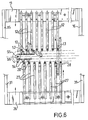
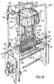
- the other weaving machine for manufacturing the fabric of Figure 1, illustrated in Figure 10 differs from the weaving machine illustrated in Figure 2 mainly in the means for guiding the warp yarns A,B toward the fabric formation area and in the means for guiding the bias yarns E,F toward the fabric formation area.
- the tubes are rigidly carried by a set of respective plates parallel one to the other and mounted on a common holder rod: the tubes, plates and rod of the first guide member for the warp yarns A are indicated with 101,102,103 respectively; the tubes, plates and rod of the second guiding member for the warp yarns B are indicated with 104,105,106 respectively.
- the plates 102,105 have each a notch indicated with 107 for the plates 102 and with 108 for the plate 105.
- the rod 103 is borne at each end by an arm 190, which arm at one end is rigidly connected to the rod 103 and at the other end is pivotally coupled to a fixed pivot 191;
- the rod 106 is correspondingly borne at each end by an arm 192, which arm at one end is rigidly connected to the rod 106 and at the other end is pivotally coupled to said fixed pivot 191.
- the fixed pivots 191 of the arms 190,192 are disposed along an axis X corresponding to the starting position Z of the formed fabric T.
- the two rods 103,106 are each reciprocated rotatively about the pivots 191, as in the first machine the bars 11,26 are reciprocated rotatively about the shafts 17,32 respectively; such rods 103,106 are driven by the main electric motor 118 through kinematic means analogous to that described for the first machine.
- a cogged belt 193 is provided, and instead of the plates 52 with the eyelets 54 a set of straight guide tubes 194 is provided.
- Each guide tube 194 is fixed to the cogged belt 193 in the cavity between two consecutive cogs and each bias yarn is passed through a respective of said guide tubes 194.
- two cogged pulleys 155,157 are provided around which the cogged belt 193 is wound.
- a feeder unit for the bias yarns E,F comprising a carousel 163 as in the first machine.
- the box-type holder elements 165 are moved according to a circular path; for this purpose a drum 195 is provided which carries all the box-type holder elements 165 with the reels 164.
- the drum 195 is driven rotatably about its axis by the electric motor 118 through the shaft 171, the drive unit 172, the cogged drive belt 175 and the cogged wheel 174; the connection between the cogged wheel 174 and the drum 195 can be made through a gear, driven by such cogged wheel 174, which meshes with a crown gear of the drum 195.
- the second machine provides also a tension compensator 196 of known type applied to each bias yarn between the respective reel 164 and the respective guide tube 194.
- the pickers 136,137 of the second machine are disposed at opposite sides instead of being disposed at the same side like in the first machine.
- the second machine substantially operates as the first machine.
- the detail view of Figure 12 corresponds to the detail view of Figure 5.
- the rod 106 has been rotated toward the rod 103 and a shed has been formed through which a weft yarn C is inserted by means of the picker 136.
- the function of the two reeds 78,79 of the first machine is performed in the second machine by two set of plates 185,186.
- the plates 185,186 are mounted on respective holder shafts 187,188 each mounted on the bearing structure 110 and reciprocated rotatively about its axis.
- the plates 185,186 and the shafts 187,188 are not shown in Figure 10 but only in the Figures 11,12,13.
- the described second machine offers several advantages.
- the guide tubes 101,104,194 permit to guide each yarn nearly up to the crisscross point. In this way interference and therefore rubbing among the yarns is prevented. Moreover, an accurate distribution of the yarns and therefore a high uniformity of the fabric is guaranteed.
- the use of the guide tubes permits also to obtain a fabric having a high fineness.
- the plates 102,105 constitute a rigid support for the guide tubes 101,104 respectively. Moreover, as seen above, the notches 107,108 of such plates 102,105 guide the pickers during the insertion of the weft yarns. There is also to point out that the plates 102,105 constitute guides for the plates 185,186 during the movement of these latter, in order to avoid rubbing on the yarns.
- the rods 103,106 with the respective plates 102,105 and tubes 101,104, the shafts 187,188 with the respective plates 185,186, the cogged belt 193 with the guide tubes 194, may all be easy assembled and disassembled, and therefore each component may be easy changed for instance when the weaving machine must be prepared for making a fabric of a different fineness.
Landscapes
- Engineering & Computer Science (AREA)
- Textile Engineering (AREA)
- Woven Fabrics (AREA)
- Looms (AREA)
- Macromolecular Compounds Obtained By Forming Nitrogen-Containing Linkages In General (AREA)
Claims (22)
- Tetraaxialgewebe mit Kettgarnen (A,B), Schußgarnen (C,D), ersten Diagonalgarnen (E) und zweiten Diagonalgarnen (F), die einander und die Kett-(A,B) und Schuß-(C,D)-Garne in zwei verschiedenen Diagonalrichtungen kreuzen, dadurch gekennzeichnet, daß eine erste Reihe von Kettgarnen (A) von den Schußgarnen (C,D) überlagert wird und ihrerseits die ersten (E) und zweiten (F) Diagonalgarne überlagert, und daß eine zweite Reihe von Kettgarnen (B), die mit den Kettgarnen (A) in der ersten Reihe wechseln, die Schußgarne (C,D) überlagert und ihrerseits von den ersten (E) und den zweiten (F) Diagonalgarnen überlagert wird.
- Tetraaxialgewebe nach Anspruch 1, wobei die ersten (E) und zweiten (F) Diagonalgarne einander in zwei zueinander senkrechten Richtungen schneiden.
- Tetraaxialgewebe nach Anspruch 1 oder 2, wobei die ersten (E) und zweiten (F) Diagonalgarne in einem Winkel von 45° zu den Kettgarnen (A,B) und den Schußgarnen (C,D) angeordnet sind.
- Tetraaxialgewebe nach einem der vorangehenden Ansprüche, wobei die Überkreuzungen aller Garne (A,B,C,D,E,F) an gemeinsamen Überkreuzungspunkten liegen, an jedem von denen sie ein Kettgarn (A;B), ein Schußgarn (C;D), ein erstes Diagonalgarn (E) sowie ein zweites Diagonalgarn (F) kreuzen.
- Webmaschine zum Herstellen des Gewebes nach den vorangehenden Ansprüchen, die Einrichtungen (11,12,13;26,27,28) umfaßt, die die Schußgarne (A,B) zu einem Gewebebildungsbereich führen, sowie Einrichtungen (36,37), die die Schußgarne (C,D) durch das Fach von Kettgarnen (A,B) in dem Gewebebildungsbereich leiten, und die des weiteren Einrichtungen (52,53,54) umfaßt, die die Diagonalgarne (E,F) in dem Gewebebildungsbereich so führen, daß die Diagonalgarne (E,F) einander und die Kett-(A,B) und Schuß-(C,D)-Garne in zwei verschiedenen Diagonalrichtungen kreuzen, wobei die Einrichtungen, die die Kettgarne (A,B) führen, ein erstes Führungselement (11,12,13) umfassen, das die erste Reihe von Kettgarnen (A) führt, und ein zweites Führungselement (26,27,28), das die zweite Reihe von Kettgarnen (B) versetzt zu der ersten Reihe von Kettgarnen (A) führt, wobei die ersten (11,12,13) und die zweiten (26,27,28) Führungselemente an nebeneinanderliegenden Positionen angeordnet sind, dadurch gekennzeichnet, daß das erste und das zweite Führungselement zwischen einer hinteren Position (G;H), in der ihre entsprechende Reihe von Kettgarnen (A;B) auf einer Seite in bezug auf die Diagonalgarne (E,F) und die andere Reihe von Kettgarnen in der hinteren Position liegt, und einer vorderen Position (G';H') bewegt werden können, in der ihre entsprechende Reihe von Kettgarnen (A;B) auf der gegenüberliegenden Seite in bezug auf die Diagonalgarne (E,F) und die andere Reihe von Kettgarnen in der hinteren Position liegt, wobei zwischen der ersten Reihe von Kettgarnen (A) unter der Führung des ersten Führungselementes (11,12,13) in der vorderen Position (G') und der zweiten Reihe von Kettgarnen (B) unter der Führung des zweiten Führungselementes (26,27,28) in der hinteren Position (H) ein erstes Fach (W1) zum Hindurchleiten eines Schußgarns (D) gebildet wird, und zwischen der ersten Reihe von Kettgarnen (A) unter der Führung des ersten Führungselementes (11,12,13) in der hinteren Position (G) und der zweiten Reihe von Kettgarnen (B) unter der Führung des zweiten Führungselementes (26,27,28) in der vorderen Position (H') ein zweites Fach (W2) zum Hindurchleiten eines weiteren Schußgarns (C) gebildet wird.
- Webmaschine nach Anspruch 5, wobei jedes Führungselement einen Satz Nadeln (12;27) umfaßt, die in einem gemeinsamen Halter (11;26) angebracht sind, wobei jede Nadel (12;27) mit einem Loch (13;28) versehen ist, durch das ein entsprechendes Kettgarn (A;B) geleitet wird.
- Webmaschine nach Anspruch 6, wobei der Halter (11;26) der Nadeln (12;27) hin und her gedreht wird, um die Kettgarne (A;B) zwischen der hinteren Position (G;H) und der vorderen Position (G';H') zu bewegen.
- Webmaschine nach Anspruch 5 oder 7, wobei die Einrichtung, die die Diagonalgarne führt, eine Gruppe von Führungselementen (52) umfaßt, die in schrittweiser Bewegung um einen endlosen Weg herum mitgeführt werden, wobei jedes Führungselement (52) mit einer Öse (54) versehen ist, durch die ein entsprechendes Diagonalgarn (E,F) geleitet wird.
- Webmaschine nach Anspruch 8, wobei die Führungselemente (52) an einer Kette (53) angebracht sind, die um den endlosen Weg herum angetrieben wird.
- Webmaschine nach Anspruch 8, wobei an der Position der Führungselemente (52) ein Karussell (63) vorhanden ist, das in Bewegung in zeitgesteuerter Beziehung zur Bewegung der Führungselemente (52) eine Vielzahl von Garnspeichervorrichtungen (64) mitführt, aus der sich jeweils eines oder mehrere Garne erstrecken, die durch die Ösen (54) in den entsprechenden Führungselementen (52) geleitet werden.
- Webmaschine nach Anspruch 10, wobei die Führungselemente (52) in Bewegung um einen länglichen endlosen Weg mit zwei geraden Abschnitten und zwei Kreisbogenabschnitten, die die beiden geraden Abschnitte miteinander verbinden, herum mitgeführt werden, und wobei das Karussell (53) in Bewegung die Garnspeichervorrichtungen (64) um einen im wesentlichen rhombusförmigen Weg herum mitführt, wobei die spitzen Winkel des Rhombus an den Kreisbogenabschnitten angeordnet sind.
- Webmaschine nach Anspruch 5, die zwei Einführelemente für die Schußgarne (36,37) jeweils an einem entsprechenden der beiden Fächer (W1,W2) umfaßt, die zwischen den Kettgarnen (A,B) gebildet werden.
- Webmaschine nach Anspruch 8, die Zeitsteuereinrichtungen (21,22,38,39,77) umfaßt, die nacheinander für jeden Webzyklus steuern:das erste Führungselement (11,12,13) so, daß es sich in die vordere Position (G') bewegt, und das zweite Führungselement (26,27,28) so, daß es in der hinteren Position (H) gehalten wird, um das erste Fach (W1) durch die Kettgarne (A,B) hindurch zu bilden;ein Schußgarn (D) so, daß es durch das erste Fach (W1) eingeführt wird;das erste Führungselement (11,12,13) so, daß es sich in die hintere Position (G) bewegt;die Führungselemente (52,54) für die Diagonalgarne (E,F) so, daß sie sich um einen Schritt vorwärtsbewegen;das zweite Führungselement (26,27,28) so, daß es sich in die vordere Position (H') bewegt, und das erste Führungselement (11,12,13) so, daß es in der hinteren Position (G) gehalten wird, um das zweite Fach (W2) durch die Kettgarne (A,B) hindurch zu bilden;ein weiteres Schußgarn (C) so, daß es durch das zweite Fach (W2) eingeführt wird;das zweite Führungselement (26,27,28) so, daß es in die hintere Position (H) bewegt wird; unddie Führungselemente (52,54) für die Diagonalgarne so, daß sie um einen Schritt nach vorn bewegt werden.
- Webmaschine nach Anspruch 5, wobei jedes Führungselement einen Satz Führungsröhren (101;104) umfaßt, die starr von einem Satz entsprechender Platten (102;105) getragen werden, die parallel zueinander und an einem gemeinsamen Halter (103;106) angebracht sind, wobei durch jede Führungsröhre (101;104) ein entsprechendes Kettgarn (A;B) geleitet wird.
- Webmaschine nach Anspruch 14, wobei der Halter (103;106) der Platten (102;105) entlang einer Achse (X), die der Ausgangsposition (Z) des gebildeten Gewebes (T) entspricht, hin und her gedreht wird, um die Kettgarne (A;B) zwischen der hinteren Position und der vorderen Position zu bewegen.
- Webmaschine nach Anspruch 15, wobei die Platten (102;105) jeweils eine Einkerbung (107;108) aufweisen, wobei alle Einkerbungen (107,108) fluchtend sind, so daß ein Durchlaß für die Einrichtungen (136;137), die die Schußgarne (C;D) leiten, gebildet wird, wenn sich die Platten (102,105) der beiden Sätze von Platten in einer Position befinden, die der Bildung des ersten Fachs oder des zweiten Fachs entspricht.
- Webmaschine nach Anspruch 5 oder 16, wobei die Einrichtungen, die die Diagonalgarne führen, einen Satz Führungsröhren (194) umfassen, die in schrittweiser Bewegung um einen endlosen Weg herum mitgeführt werden, wobei durch jede Führungsröhre (194) ein entsprechendes Diagonalgarn (E,F) geleitet wird.
- Webmaschine nach Anspruch 17, wobei die Führungsröhren (194) an einem Zahnriemen (193) angebracht sind, der um einen endlosen Weg herum angetrieben wird.
- Webmaschine nach Anspruch 17, wobei an der Position der Führungsröhren (194) ein Karussell (163) vorhanden ist, das in Bewegung in zeitgesteuerter Beziehung zur Bewegung der Führungsröhren (194) eine Vielzahl von Garnspeichervorrichtungen (164) mitführt, aus denen sich ein oder mehrere Garne erstrecken, die durch die entsprechenden Führungsröhren (194) geleitet werden.
- Webmaschine nach Anspruch 10 oder 19, wobei das Karussell (63;163) drehbar um seine Achse bewegt wird.
- Webmaschine nach Anspruch 7, wobei zwei Riete (78,79) vorhanden sind, die drehbar hin und her bewegt werden, wobei jedes Riet (78;79), wenn ein entsprechendes Schußgarn (C;D) eingeführt ist, eine entsprechende Reihe von Kettgarnen (A;B) getrennt hält und das Schußgarn (C;D) fest an das zuvor gebildete Gewebe (T) drückt.
- Webmaschine nach Anspruch 16, wobei zwei Sätze von Platten (185;186) vorhanden sind, die an zwei entsprechenden Haltern (187,188) angebracht sind, die drehbar hin und her bewegt werden, wobei jeder Satz von Platten (185;186), wenn ein entsprechendes Schußgarn (C;D) eingeführt ist, eine entsprechende Reihe von Kettgarnen (A;B) getrennt hält und das Schußgarn (C;D) fest an das zuvor gebildete Gewebe (T) drückt.
Applications Claiming Priority (2)
| Application Number | Priority Date | Filing Date | Title |
|---|---|---|---|
| ITMI912697A IT1251683B (it) | 1991-10-11 | 1991-10-11 | Tessuto tetrassiale e macchina di tessitura per la sua fabbricazione |
| ITMI912697 | 1991-10-11 |
Publications (2)
| Publication Number | Publication Date |
|---|---|
| EP0536735A1 EP0536735A1 (de) | 1993-04-14 |
| EP0536735B1 true EP0536735B1 (de) | 1996-11-20 |
Family
ID=11360851
Family Applications (1)
| Application Number | Title | Priority Date | Filing Date |
|---|---|---|---|
| EP92117143A Expired - Lifetime EP0536735B1 (de) | 1991-10-11 | 1992-10-08 | Tetraaxialgewebe und Webstuhl zum Herstellen davon |
Country Status (6)
| Country | Link |
|---|---|
| US (1) | US5351722A (de) |
| EP (1) | EP0536735B1 (de) |
| JP (1) | JPH06101135A (de) |
| AT (1) | ATE145439T1 (de) |
| DE (1) | DE69215324T2 (de) |
| IT (1) | IT1251683B (de) |
Families Citing this family (17)
| Publication number | Priority date | Publication date | Assignee | Title |
|---|---|---|---|---|
| US5375627A (en) * | 1993-09-08 | 1994-12-27 | Howa Machinery, Ltd. | Method and weaving machine for producing multi-axial fabric |
| US5472020A (en) * | 1993-09-08 | 1995-12-05 | Howa Machinery, Ltd. | Multi-axial fabric with triaxial and quartaxial portions |
| DE69606571D1 (de) * | 1995-04-07 | 2000-03-16 | Danilo Jaksic | Webstuhl zum dreiachsigen Weben |
| JP3476291B2 (ja) | 1995-11-22 | 2003-12-10 | 富士写真フイルム株式会社 | 箔押し方法及び装置 |
| US6159239A (en) * | 1998-08-14 | 2000-12-12 | Prodesco, Inc. | Woven stent/graft structure |
| US6257629B1 (en) * | 1999-03-11 | 2001-07-10 | Joel Weichelt | Automatic process and machine for weaving one continuous rope |
| US6480759B1 (en) * | 2000-06-23 | 2002-11-12 | Storage Technology Corporation | Diagnostic port between independent robots |
| ITMI20011665A1 (it) * | 2001-07-31 | 2003-01-31 | Mamiliano Dini | Tessuto tetrassiale e macchina per la sua produzione |
| ES2255774B1 (es) * | 2002-03-20 | 2007-12-16 | Universitat Politecnica De Catalunya | Telar o maquina de tejer para la fabricacion de estructuras laminares tridimensionales multiaxiales. |
| ES2255775B1 (es) * | 2002-04-08 | 2007-12-16 | Universitat Politecnica De Catalunya | Maquina de tejer plurifuncional para la fabricacion de estructuras tridimensionales radiales o multiaxiales. |
| FR2907803B1 (fr) * | 2006-10-27 | 2009-01-23 | Airbus France Sas | Systeme de tissage d'un angle continu |
| CN102140722B (zh) * | 2010-01-28 | 2012-07-11 | 来永泰 | 超高速无梭窄幅织机 |
| FR2991228B1 (fr) | 2012-05-29 | 2015-03-06 | Airbus Operations Sas | Procede et dispositif de realisation d'un panneau composite auto-raidi |
| KR101824783B1 (ko) * | 2012-12-21 | 2018-02-01 | 나이키 이노베이트 씨.브이. | 로크아웃을 갖는 직조된 신발류 갑피 |
| EP2757183B1 (de) * | 2013-01-21 | 2019-10-09 | Autoliv Development AB | Verbesserungen an oder im Zusammenhang mit Airbags |
| CN103726193A (zh) * | 2013-12-30 | 2014-04-16 | 吴江金名来丝绸进出口有限公司 | 一种抗菌面料 |
| WO2015126337A1 (en) * | 2014-02-18 | 2015-08-27 | Kordsa Global Endustriyel Iplik Ve Kord Bezi Sanayi Ve Ticaret Anonim Sirketi | Re-weaving machine and re-woven tire cord fabric |
Family Cites Families (9)
| Publication number | Priority date | Publication date | Assignee | Title |
|---|---|---|---|---|
| FR446368A (fr) * | 1912-07-23 | 1912-12-03 | William George Trautvetter | Perfectionnements aux tissus |
| US3999578A (en) * | 1975-08-11 | 1976-12-28 | Barber-Colman Company | Triaxial weaving machine with heddle shifting means and method |
| US4020876A (en) * | 1976-01-29 | 1977-05-03 | Barber-Colman Company | Triaxial weaving machine with flexible passageways for guiding warp strands |
| US4031922A (en) * | 1976-03-25 | 1977-06-28 | Barber-Colman Company | Vertically arranged triaxial weaving machine |
| US4170249A (en) * | 1978-09-25 | 1979-10-09 | Barber-Colman Company | Warp length compensator for a triaxial weaving machine |
| GB2117418A (en) * | 1982-03-19 | 1983-10-12 | Hinaya Kk | Fabric and tubular article using said fabric |
| US4512373A (en) * | 1983-05-09 | 1985-04-23 | Barber-Colman Company | Feeding and guiding means for triaxial fabric forming machine |
| US4438173A (en) * | 1983-07-21 | 1984-03-20 | Barber-Colman Company | Triaxial fabric |
| JPS6392751A (ja) * | 1986-10-01 | 1988-04-23 | 小河原 通弘 | 四軸織物及び四軸織機 |
-
1991
- 1991-10-11 IT ITMI912697A patent/IT1251683B/it active IP Right Grant
-
1992
- 1992-10-08 EP EP92117143A patent/EP0536735B1/de not_active Expired - Lifetime
- 1992-10-08 DE DE69215324T patent/DE69215324T2/de not_active Expired - Fee Related
- 1992-10-08 AT AT92117143T patent/ATE145439T1/de not_active IP Right Cessation
- 1992-10-12 JP JP4273266A patent/JPH06101135A/ja active Pending
-
1993
- 1993-12-16 US US08/168,582 patent/US5351722A/en not_active Expired - Fee Related
Also Published As
| Publication number | Publication date |
|---|---|
| DE69215324D1 (de) | 1997-01-02 |
| US5351722A (en) | 1994-10-04 |
| ITMI912697A1 (it) | 1993-04-11 |
| ATE145439T1 (de) | 1996-12-15 |
| EP0536735A1 (de) | 1993-04-14 |
| JPH06101135A (ja) | 1994-04-12 |
| ITMI912697A0 (it) | 1991-10-11 |
| DE69215324T2 (de) | 1997-06-12 |
| IT1251683B (it) | 1995-05-19 |
Similar Documents
| Publication | Publication Date | Title |
|---|---|---|
| EP0536735B1 (de) | Tetraaxialgewebe und Webstuhl zum Herstellen davon | |
| US3834424A (en) | Three-dimensional fabric, and method and loom construction for the production thereof | |
| EP0630433B1 (de) | Multiaxiale garnstruktur | |
| US3818951A (en) | Loom | |
| RU2239009C2 (ru) | Бесчелночный лентоткацкий станок для изготовления узких тканых изделий, а также узкое тканое изделие | |
| US7237575B2 (en) | Tetraxial fabric and machine for its manufacture | |
| CN101346499A (zh) | 用于制造带、尤其是织入导电细丝具体为天线细丝的标签带的导纬针织带机 | |
| US3746051A (en) | Machine for making a partly woven and partly knitted fabric | |
| US5375627A (en) | Method and weaving machine for producing multi-axial fabric | |
| JPS6240455B2 (de) | ||
| JPS62289649A (ja) | 杼無織機におけるよこ糸插入装置によこ糸を供給する装置 | |
| US3682205A (en) | Needle loom | |
| US3136343A (en) | Needle loom for y tapes | |
| US5694982A (en) | Weft thread selection device | |
| US5472020A (en) | Multi-axial fabric with triaxial and quartaxial portions | |
| US5505231A (en) | Projectile guiding elements synchronously movable with a full width power loom sley | |
| US3720236A (en) | Arrangement for forming a selvage for use on a loom | |
| CN101253287B (zh) | 在织机上形成纱罗织物的方法和装置 | |
| US3580295A (en) | Partly woven and partly knitted fabric and apparatus for making the same | |
| SU626131A1 (ru) | Узорообразующее устройство ворсовой основов зальной машины | |
| US3664380A (en) | Loom with traveling shed | |
| US3620048A (en) | Weft supplying device for a warp knitting machine | |
| JP2002513867A (ja) | ケリムやゴブランなどのパターンを形成する横糸をもつ織物を製造するための織機および方法 | |
| US4440197A (en) | Shuttleless loom | |
| US4151866A (en) | Loom for the weaving of two and/or three thread fabrics |
Legal Events
| Date | Code | Title | Description |
|---|---|---|---|
| PUAI | Public reference made under article 153(3) epc to a published international application that has entered the european phase |
Free format text: ORIGINAL CODE: 0009012 |
|
| AK | Designated contracting states |
Kind code of ref document: A1 Designated state(s): AT BE CH DE DK ES FR GB GR IE IT LI LU MC NL PT SE |
|
| 17P | Request for examination filed |
Effective date: 19931007 |
|
| 17Q | First examination report despatched |
Effective date: 19950420 |
|
| GRAH | Despatch of communication of intention to grant a patent |
Free format text: ORIGINAL CODE: EPIDOS IGRA |
|
| GRAH | Despatch of communication of intention to grant a patent |
Free format text: ORIGINAL CODE: EPIDOS IGRA |
|
| GRAA | (expected) grant |
Free format text: ORIGINAL CODE: 0009210 |
|
| AK | Designated contracting states |
Kind code of ref document: B1 Designated state(s): AT BE CH DE DK ES FR GB GR IE IT LI LU MC NL PT SE |
|
| PG25 | Lapsed in a contracting state [announced via postgrant information from national office to epo] |
Ref country code: NL Free format text: LAPSE BECAUSE OF FAILURE TO SUBMIT A TRANSLATION OF THE DESCRIPTION OR TO PAY THE FEE WITHIN THE PRESCRIBED TIME-LIMIT Effective date: 19961120 Ref country code: LI Effective date: 19961120 Ref country code: GR Free format text: LAPSE BECAUSE OF FAILURE TO SUBMIT A TRANSLATION OF THE DESCRIPTION OR TO PAY THE FEE WITHIN THE PRESCRIBED TIME-LIMIT Effective date: 19961120 Ref country code: ES Free format text: THE PATENT HAS BEEN ANNULLED BY A DECISION OF A NATIONAL AUTHORITY Effective date: 19961120 Ref country code: DK Effective date: 19961120 Ref country code: CH Effective date: 19961120 Ref country code: BE Effective date: 19961120 Ref country code: AT Effective date: 19961120 |
|
| REF | Corresponds to: |
Ref document number: 145439 Country of ref document: AT Date of ref document: 19961215 Kind code of ref document: T |
|
| REG | Reference to a national code |
Ref country code: IE Ref legal event code: FG4D Free format text: 70674 |
|
| REF | Corresponds to: |
Ref document number: 69215324 Country of ref document: DE Date of ref document: 19970102 |
|
| ITF | It: translation for a ep patent filed | ||
| PG25 | Lapsed in a contracting state [announced via postgrant information from national office to epo] |
Ref country code: SE Effective date: 19970220 Ref country code: PT Effective date: 19970220 |
|
| ET | Fr: translation filed | ||
| NLV1 | Nl: lapsed or annulled due to failure to fulfill the requirements of art. 29p and 29m of the patents act | ||
| REG | Reference to a national code |
Ref country code: CH Ref legal event code: PL |
|
| PLBE | No opposition filed within time limit |
Free format text: ORIGINAL CODE: 0009261 |
|
| PG25 | Lapsed in a contracting state [announced via postgrant information from national office to epo] |
Ref country code: IE Free format text: LAPSE BECAUSE OF NON-PAYMENT OF DUE FEES Effective date: 19971008 |
|
| PG25 | Lapsed in a contracting state [announced via postgrant information from national office to epo] |
Ref country code: LU Free format text: LAPSE BECAUSE OF NON-PAYMENT OF DUE FEES Effective date: 19971031 |
|
| 26N | No opposition filed | ||
| PG25 | Lapsed in a contracting state [announced via postgrant information from national office to epo] |
Ref country code: MC Free format text: LAPSE BECAUSE OF NON-PAYMENT OF DUE FEES Effective date: 19980430 |
|
| PGFP | Annual fee paid to national office [announced via postgrant information from national office to epo] |
Ref country code: GB Payment date: 20000919 Year of fee payment: 9 |
|
| PGFP | Annual fee paid to national office [announced via postgrant information from national office to epo] |
Ref country code: DE Payment date: 20000925 Year of fee payment: 9 |
|
| PGFP | Annual fee paid to national office [announced via postgrant information from national office to epo] |
Ref country code: FR Payment date: 20001030 Year of fee payment: 9 |
|
| PG25 | Lapsed in a contracting state [announced via postgrant information from national office to epo] |
Ref country code: GB Free format text: LAPSE BECAUSE OF NON-PAYMENT OF DUE FEES Effective date: 20011008 |
|
| REG | Reference to a national code |
Ref country code: GB Ref legal event code: IF02 |
|
| GBPC | Gb: european patent ceased through non-payment of renewal fee |
Effective date: 20011008 |
|
| PG25 | Lapsed in a contracting state [announced via postgrant information from national office to epo] |
Ref country code: FR Free format text: LAPSE BECAUSE OF NON-PAYMENT OF DUE FEES Effective date: 20020628 |
|
| PG25 | Lapsed in a contracting state [announced via postgrant information from national office to epo] |
Ref country code: DE Free format text: LAPSE BECAUSE OF NON-PAYMENT OF DUE FEES Effective date: 20020702 |
|
| REG | Reference to a national code |
Ref country code: FR Ref legal event code: ST |
|
| PG25 | Lapsed in a contracting state [announced via postgrant information from national office to epo] |
Ref country code: IT Free format text: LAPSE BECAUSE OF NON-PAYMENT OF DUE FEES Effective date: 20051008 |