EP0536645A2 - Preparation on a dialysis apparatus of the necessary bicarbonate solution for bicarbonate dialysis - Google Patents
Preparation on a dialysis apparatus of the necessary bicarbonate solution for bicarbonate dialysis Download PDFInfo
- Publication number
- EP0536645A2 EP0536645A2 EP92116841A EP92116841A EP0536645A2 EP 0536645 A2 EP0536645 A2 EP 0536645A2 EP 92116841 A EP92116841 A EP 92116841A EP 92116841 A EP92116841 A EP 92116841A EP 0536645 A2 EP0536645 A2 EP 0536645A2
- Authority
- EP
- European Patent Office
- Prior art keywords
- container
- dialysis
- bicarbonate
- liquid
- solution
- Prior art date
- Legal status (The legal status is an assumption and is not a legal conclusion. Google has not performed a legal analysis and makes no representation as to the accuracy of the status listed.)
- Withdrawn
Links
Images


Classifications
-
- A—HUMAN NECESSITIES
- A61—MEDICAL OR VETERINARY SCIENCE; HYGIENE
- A61M—DEVICES FOR INTRODUCING MEDIA INTO, OR ONTO, THE BODY; DEVICES FOR TRANSDUCING BODY MEDIA OR FOR TAKING MEDIA FROM THE BODY; DEVICES FOR PRODUCING OR ENDING SLEEP OR STUPOR
- A61M1/00—Suction or pumping devices for medical purposes; Devices for carrying-off, for treatment of, or for carrying-over, body-liquids; Drainage systems
- A61M1/14—Dialysis systems; Artificial kidneys; Blood oxygenators ; Reciprocating systems for treatment of body fluids, e.g. single needle systems for hemofiltration or pheresis
- A61M1/16—Dialysis systems; Artificial kidneys; Blood oxygenators ; Reciprocating systems for treatment of body fluids, e.g. single needle systems for hemofiltration or pheresis with membranes
- A61M1/1654—Dialysates therefor
- A61M1/1656—Apparatus for preparing dialysates
- A61M1/1666—Apparatus for preparing dialysates by dissolving solids
-
- A—HUMAN NECESSITIES
- A61—MEDICAL OR VETERINARY SCIENCE; HYGIENE
- A61M—DEVICES FOR INTRODUCING MEDIA INTO, OR ONTO, THE BODY; DEVICES FOR TRANSDUCING BODY MEDIA OR FOR TAKING MEDIA FROM THE BODY; DEVICES FOR PRODUCING OR ENDING SLEEP OR STUPOR
- A61M1/00—Suction or pumping devices for medical purposes; Devices for carrying-off, for treatment of, or for carrying-over, body-liquids; Drainage systems
- A61M1/14—Dialysis systems; Artificial kidneys; Blood oxygenators ; Reciprocating systems for treatment of body fluids, e.g. single needle systems for hemofiltration or pheresis
- A61M1/16—Dialysis systems; Artificial kidneys; Blood oxygenators ; Reciprocating systems for treatment of body fluids, e.g. single needle systems for hemofiltration or pheresis with membranes
- A61M1/1654—Dialysates therefor
- A61M1/1656—Apparatus for preparing dialysates
- A61M1/1668—Details of containers
Definitions
- the invention relates to a method of the type corresponding to the preamble of claim 1, a container suitable therefor and a device for carrying out the method with the container.
- dialysis fluid In hemodialysis, relatively large amounts of dialysis fluid are required. Depending on the duration of the treatment, 150 to 180 liters per dialysis can be expected. Since it requires considerable transport effort to produce such amounts of liquid in a pharmaceutical company remote from the dialysis site in the final dilution and to transport it to the dialysis site, the early stage was to provide dialysis fluid in the form of highly concentrated solutions.
- a further stage of development is the delivery of quantities of dry concentrate in plastic cartridges, calculated for each dialysis, which, for example, hold 650 g of the salt in question.
- Purified water flows through the cartridges and their contents dissolve.
- the purified water is available on the appropriate dialysis machines and is obtained by reverse osmosis from clean tap water in high quality, so that it is largely free of all ingredients.
- the cartridge concept is particularly important in bicarbonate hemodialysis. Two partial concentrates are required, one of which contains ions Na+, K+, Ca2+ and Mg2+ and the other contains sodium hydrogen carbonate. Because of the low solubility of calcium carbonate, the calcium carbonate would fail if the two components were brought together early.
- the object of the invention is to make the provision of the bicarbonate solution for bicarbonate hemodialysis simple and economical.
- the invention also extends to a container which is adapted to the described method in the manner set out in claim 2.
- the container is arranged in the operating position so that the filter base is horizontal so that the dry concentrate can lie thereon, and that the inlet is arranged above and the outlet below the filter base.
- the water flows vertically through the dry concentrate, thereby dissolving the amount of saturation.
- the volume of the container is not particularly large. It is determined by the amount of bicarbonate to be taken up and an amount of water which allows the saturated bicarbonate solution to be formed rapidly and uniformly and to be removed from the container without problems. Containers of about 0.5 to 2 liters are possible.
- the filter base can be formed according to claim 3 by a ceramic filter, the pore size according to claim 4 can be 100 to 160 microns.
- the container can be provided with a removable glass connection spout, which is tightened with a union nut and sealed with an elastic seal.
- the union nut is screwed onto the glass container and connects the connection nozzle to the actual glass container.
- the liquid outlet can be formed by a glass connecting nozzle which is integral with the glass container.
- connection spouts are at the liquid inlet and liquid outlet are expensive to manufacture if they are made of glass, whether in one piece or separately, since only small series can be considered.
- a one-piece connection spout made of plastic for the liquid inlet and / or to choose for the liquid outlet which is not exposed to the disadvantage of being easily damaged during cleaning and which may even be a commercially available purchase part intended for other purposes.
- this connection nozzle can be screwed on.
- the connecting sleeves made of plastic for the liquid inlet and for the liquid outlet can be sealed with a sealing ring against the glass body (claim 7) and have a peripheral edge as a reinforcement, for attack during handling and for protecting the threaded connector of the container (claim 8).
- a device for carrying out the method described at the beginning can be used in the be designed in accordance with claim 9.
- the container and the device for maintaining a certain liquid level are both arranged outside the dialysis machine and together form a system which ensures the proper formation of the saturated solution because liquid is always above the solid bicarbonate and in this way there is a certain minimum contact time.
- the container is assigned a ballast arranged approximately at the same height with a float valve, which interacts with the container in the manner of communicating tubes, so that there is always the same liquid level in both and the closed position of the Float valve in the ballast tank determines the liquid level in the actual tank.
- the container can be designed to perform a single dialysis. However, it can also be dimensioned larger, so that several dialyses can be carried out in succession in a single dialysis machine with one filling of the container or the container is connected to several dialysis machines, so that several dialyses can be carried out simultaneously.
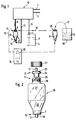
- Fig. 1 denotes the dialysis machine, which is on the patient's bed during dialysis and is connected to the patient via lines 1 and 2.
- the blood flows through lines 1 and 2 introduced and returned to the patient, which is subjected to dialysis treatment in the dialysis machine, ie the removal of urinary constituents from the blood.
- This takes place in the so-called dialyzer (not shown), for example a capillary dialyzer, in which a membrane is present, on one side of which the blood is present and on the other side of which the dialysis fluid is present and through which the substances to be removed diffuse out of the blood into the dialysis fluid.
- dialyzer for example a capillary dialyzer, in which a membrane is present, on one side of which the blood is present and on the other side of which the dialysis fluid is present and through which the substances to be removed diffuse out of the blood into the dialysis fluid.
- the dialysis liquid is prepared from two components, namely a partial concentrate containing the bicarbonate and a further partial concentrate containing ions such as Na+, K+, Ca2+ and Mg2+.
- the latter is supplied in the form of a liquid concentrate 3 in canisters 4 of, for example, ten liters of content and is removed directly from the canister 4 by the dialysis machine 10 via a line 5.
- the partial concentrate containing the bicarbonate is produced from a dry or solid bicarbonate composition 6, which is in a container 20 made of glass of about 1 liter content on a horizontal filter base 7 with fine pores of 100 to 160 ⁇ m pore size in an amount calculated for dialysis located.
- the container 20 Above the filter base 7, the container 20 has a connection 51, in the case shown an inlet, below the filter base 7, a connection 52 with a connection piece 8, below the filter base 7 a connection 52.
- the connection 51 comprises a connection piece 8 with a hose connector 11, via which ultrapure water purified by reverse osmosis is supplied via a line 9 formed by a hose from the dialysis machine 10. If from “above” and “below” is mentioned, the position of the container 20 in operation is always meant.
- the ultrapure water fed in via line 9 passes through the bicarbonate 6 and dissolves so much of the bicarbonate 6 that a saturated solution is obtained which contains about 8.4% sodium bicarbonate at room temperature and passes via line 12 into the dialysis machine 10, where the mixing with the other liquid concentrate supplied via line 5 and the dilution to the required physiological concentration take place.
- the container 20 is reusable. After completion of dialysis, as indicated by arrow 13, it is transferred to a cleaning and sterilizing device 14 and then from a larger, e.g. In a 25 kg sack 15, an existing supply 16 of the dry concentrate containing sodium bicarbonate is filled with an amount of bicarbonate 6 calculated for the next dialysis, which is indicated by the arrow 17. After refilling, the container 20 is again connected to the dialysis machine 10 in the direction of the arrow 18 and used again in the sense already described.
- the embodiment of the container 20 shown in FIG. 2 has an essentially cylindrical storage space 21 for the dry concentrate, which tapers downward in a conical part 22 to approximately half its diameter.
- the filter bottom 7 which is designed as a ceramic frit and is tightly inserted into the container 20 at the edge, is attached.
- the filter base 7 covers the entire cross section of the storage space 21, so that the water or the solution passes through the pores of the filter base 7 must take and there are no side roads.
- an outlet base 19 made of glass with a hose connector 11 for connecting the line 12 formed by a hose.
- the glass connector 8 is provided at the upper end of the cylindrical part 21 and comprises a disc-shaped circumferential projection 23 which rests on the end face 25 of a threaded connector 26 of the cylindrical part 21 via an elastic seal 24 and can be tightly tightened thereon by means of a union nut made of plastic 27 is.
- the threaded connector 26 has a relatively large cross section, so that a large filler cross section can be released for the dry concentrate 16.
- the measured amount of bicarbonate 6 rests on the filter base 7 and the ultrapure water introduced at the connection 51 flows through it from top to bottom.
- the saturated bicarbonate solution 57 which forms exits at the connection 52.
- 50 denotes another container for providing the bicarbonate solution required for bicarbonate hemodialysis on the dialysis machine.
- connection 52 exemplary embodiment according to FIG. 2
- both the connection 51 and the connection 52 are provided with a connecting sleeve 60 made of a suitable plastic.
- Various polymers can be used as plastics; in the exemplary embodiment, polyethylene was chosen.
- the correspondingly stable container body made of glass with a wall thickness of approximately 3 mm is provided with threaded connections 26 at both connections 51, 52 and is designed such that the connecting sleeves 60 commercially available threaded spouts with an axial hose nozzle 11 for pushing on a connecting hose, not shown, can be.
- the liquid inlet and liquid outlet are the same and the connecting sleeves 60 are interchangeable.
- the connecting sleeves 6O for liquid inlet and liquid outlet are sealed with a sealing ring 44 - in the exemplary embodiment made of silicone - which is pressed between an inner shoulder 39 of the connecting piece 6O and the end face of the respective threaded connector 26.
- the connecting nozzle 60 has a radially outwardly projecting circumferential collar 43 for the purpose of attacking when turning, reinforcing and protecting the threaded connector 26.
- the connection sleeves 6O are heat-resistant up to the temperature required for the sterilization.
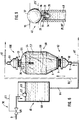
- the device designated as a whole in FIG. 6 with 100 comprises one of the above-described containers 50 made of glass and a ballast container 45 with a float valve 30.
- the container 50 and the storage container 45 are arranged together at approximately the same height outside the dialysis machine, not shown here.
- the container 50 has a liquid inlet at the bottom of the connection 52 in the exemplary embodiment and a liquid outlet at the top of the connection 51, on the connecting piece 11 of which a connecting hose (not shown) can be pushed.
- the middle part of the container 5O merges into an identical threaded connector 26, which forms the liquid outlet and onto which a plastic connecting sleeve 60 is screwed, which has a dip tube engaging through the interior of the threaded connector 26 into the interior of the container 50 53 with a filter insert 54 covering its inlet opening.
- solid bicarbonate 6 in the form of granules lies on the filter base 7 up to an upper limit 56.
- Purified water 58 is fed in via line 9 by reverse osmosis and reaches the ballast tank 45.
- the float valve 3O comprises a shut-off valve 69 which is actuated via a float 61 mechanically connected to it via a linkage 61. At a certain liquid level 63, the shut-off valve 69 is closed, so that the liquid level 63 cannot rise any higher and the volume in contact with the bicarbonate 6 is limited to a defined value.
- the supply of the pure water via line 9 takes place under the action of a pump or under the action of gravity from a higher-level storage container.
- the pure water 58 in the ballast tank 45 passes through the line 64 from its lower region into the liquid inlet at the connection 52, passes through the filter base 7 and the amount of bicarbonate 6 overlying it and then rises to a liquid level 55, which corresponds to the Liquid level 63 corresponds, as is the case with communicating tubes. If the saturated bicarbonate solution 57 standing above the solid bicarbonate is removed via the dip tube 53 and the line 46, the liquid level 55 and thus the liquid level 63 decrease, and pure water is supplied by opening the shut-off valve 69 until this is due to the position of the float 62 certain original liquid level 63 is reached again. In this way, saturated bicarbonate solution 57 is always available on line 46, without having to take care that container 10 does not run empty or saturated bicarbonate solution 57 is forced out by itself through line 46.
- the liquid inlet is provided at the bottom and the liquid outlet at the top.
- both can also be interchanged, as is to be represented by the line 64 'and the line 46' indicated by dash-dotted lines.
- the amount of solid bicarbonate 6 calculated for one (or more) dialysis (s) is initially filled through the connection 51. At the end of the dialysis, the solid bicarbonate has just been used up so that no losses occur.
- the container 50 can be used again after cleaning and sterilization.
- the entire device 100 is arranged as a separate unit outside of the dialysis machine and can be used with any type of dialysis machine without any problems with interventions in the dialysis machines which would cause problems with the medical device regulation.
- FIG. 7 and 8 show devices 2OO to 3OO, in which the float valve controlling the liquid level 55 is integrated in the container 50. No external ballast containers or the like are required here.
- the container 50 is of the same design as in FIG. 6. As far as functionally the same parts occur, the reference numbers are the same.
- the liquid inlet is again at the bottom and the liquid outlet is at the top.
- the lower connecting nozzle 6O is modified compared to the connecting nozzle 6O in FIG. 6 in that it carries a riser pipe 28 which leads through the lower threaded connector 26 and extends to the desired liquid level 55.
- the riser pipe 28 carries a float valve 40, which is shown in detail in FIG. 9. Thanks to the float valve 40, the pure water brought in through the line 9 cannot rise higher than it corresponds to the liquid level 55.
- the connecting nozzle 6O screwed onto the upper threaded connector 26 is also modified compared to the connecting nozzle 6O in FIG. 6, in that the immersion tube 53 'with the filter inlet 54 dips deeper into the container 50 by a certain distance from the extraction point to the liquid supply at the float valve 40 to accomplish.
- the liquid inlet and liquid outlet are interchanged in their position.
- the feed line 9 for pure water thus reaches the inside of the container 5O from above via the connection nozzle 6O.
- the connection nozzle 6O carries a U-shaped tube 28 'which carries the float valve 40 at the end of the upwardly bent U-leg, which defines the liquid level 55.
- the saturated bicarbonate solution formed is drawn off at the liquid outlet located below via the connecting nozzle 60 and the line 46.
- a special filter corresponding to the filter inlet 54 can be omitted here because this task is performed by the filter base 7.
- FIG. 9 A possible embodiment of the float valve 40 is indicated schematically in FIG. 9.
- the upward end of the tubes 28 and 28 ' is provided with a horizontal end face 29 transverse to its axis.
- a sealing ring 31 is inserted, for example clamped or glued, into the end, which has a central opening 33 and a sealing surface 34 at the lower edge of the opening.
- the sealing surface 34 interacts with a sealing ball 35 which has a larger diameter than the through opening 33.
- the float 37 also sinks, as a result of which the sealing ball 35 lifts off the sealing surface 34 and releases the annular space remaining between the connecting pin 36 and the inner circumference of the passage opening 33 as a passage cross section for the pure water 58.
- the float can sink until it sits on the end surface 29. Because of its light weight, the inflow of pure water is not hindered.
- the sealing ball 35 rests on the sealing surface 34, the sealing effect is no longer dependent on the load-bearing capacity of the float 37, but the arrangement is self-sealing, i.e. even if the pressure of the pure water 58 is increased, the tightness remains.
- the sunken state of the float 37 and the sealing ball 35 is indicated by dashed lines in FIG. 9.
Abstract
Description
Die Erfindung bezieht sich auf ein Verfahren der dem Oberbegriff des Anspruchs 1 entsprechenden Art, einen dafür geeigneten Behälter und eine Vorrichtung zur Durchführung des Verfahrens mit dem Behälter.The invention relates to a method of the type corresponding to the preamble of claim 1, a container suitable therefor and a device for carrying out the method with the container.
Bei der Hämodialyse werden relativ große Mengen von Dialysierflüssigkeit benötigt. Je nach Dauer der Behandlung muß mit 150 bis 180 Litern pro Dialyse gerechnet werden. Da es einen erheblichen Transportaufwand bedeutet, derartige Flüssigkeitsmengen in einem vom Dialyseort entfernten pharmazeutischen Betrieb in der Endverdünnung herzustellen und an den Dialyseort zu transportieren, wurde schon frühzeitig dazu übergegangen, Dialysierflüssigkeit in Form von hochkonzentrierten Lösungen bereitzustellen.In hemodialysis, relatively large amounts of dialysis fluid are required. Depending on the duration of the treatment, 150 to 180 liters per dialysis can be expected. Since it requires considerable transport effort to produce such amounts of liquid in a pharmaceutical company remote from the dialysis site in the final dilution and to transport it to the dialysis site, the early stage was to provide dialysis fluid in the form of highly concentrated solutions.
Eine Verfahrensweise dabei war, Trockenkonzentrat in größeren Mengen, z.B. in Säcken von 10 oder 25 kg Inhalt, an die Dialysestationen zu liefern, wo in einem besonderen Mischer ein flüssiges Konzentrat hergestellt und über Leitungen an die einzelnen an den Patientenbetten aufgestellten Dialysegeräte gepumpt wurde, wo die Endverdünnung stattfand. Diese Verfahrensweise bedeutet einen erheblichen Einrichtungsaufwand und bringt durch das Vorhandensein des ausgedehnten Leitungssystems Kontaminationsprobleme mit sich.One procedure was to deliver dry concentrate in large quantities, e.g. in bags of 10 or 25 kg, to the dialysis stations, where a liquid concentrate was produced in a special mixer and pumped via lines to the individual dialysis machines set up on the patient beds, where the final dilution took place. This procedure means a considerable outlay on equipment and brings about contamination problems due to the presence of the extensive pipe system.
Eine alternative Verfahrensweise war die Anlieferung von flüssigen Dialysekonzentraten in Kunststoffkanistern, beispielsweise aus Polyäthylen und mit einem Fassungsvermögen von 10 Liter. Diese Kanister werden am Dialysegerät aufgestellt, und es wird das Konzentrat im Dialysegerät auf die Endverdünnung gebracht.An alternative procedure was the delivery of liquid dialysis concentrates in plastic canisters, for example made of polyethylene and with a capacity of 10 liters. These canisters are placed on the dialysis machine and the concentrate is brought to the final dilution in the dialysis machine.
Bei dieser Verfahrensweise stellt die Entsorgung der vielen ziemlich großen Kunststoffkanister das bedeutendste Problem dar.With this procedure, the disposal of the many rather large plastic canisters is the most important problem.
Eine weitere Entwicklungsstufe stellt die Anlieferung von auf jeweils eine Dialyse berechneten Mengen von Trockenkonzentrat in Kunststoffpatronen dar, die beispielsweise 650 g des betreffenden Salzes fassen. Die Patronen werden von gereinigtem Wasser durchströmt, wobei sich ihr Inhalt auflöst. Das gereinigte Wasser steht an den entsprechenden Dialysegeräten zur Verfügung und wird durch Umkehrosmose von sauberem Leitungswasser in hoher Qualität gewonnen, so daß es weitestgehend von allen Inhaltsstoffen befreit ist.A further stage of development is the delivery of quantities of dry concentrate in plastic cartridges, calculated for each dialysis, which, for example, hold 650 g of the salt in question. Purified water flows through the cartridges and their contents dissolve. The purified water is available on the appropriate dialysis machines and is obtained by reverse osmosis from clean tap water in high quality, so that it is largely free of all ingredients.
Der vorbeschriebene Stand der Technik geht aus dem Buch "Grundlagen für Heimdialyse e.V. Wiss. Beratung Dr. Becker u. Prof. Dr. Schoeppe (1989) Kap. 14.4 und aus der EP-A2 278 100 hervor.The above-described state of the art can be found in the book "Foundations for Home Dialysis e.V. Scientific Advice Dr. Becker and Prof. Dr. Schoeppe (1989) Chapter 14.4 and in EP-A2 278 100.
Besonders in Betracht kommt der Patronengedanke bei der Bikarbonat-Hämodialyse. Hierbei werden zwei Teilkonzentrate benötigt, von denen eines Ionen Na⁺, K⁺, Ca²⁺ und Mg²⁺ und das andere das Natriumhydrogencarbonat enthält. Wegen der geringen Löslichkeit von Kalziumkarbonat würde bei einer frühzeitigen Zusammenbringung der beiden Komponenten das Kalziumkarbonat ausfallen.The cartridge concept is particularly important in bicarbonate hemodialysis. Two partial concentrates are required, one of which contains ions Na⁺, K⁺, Ca²⁺ and Mg²⁺ and the other contains sodium hydrogen carbonate. Because of the low solubility of calcium carbonate, the calcium carbonate would fail if the two components were brought together early.
Wenn das das Bikarbonat enthaltende sogenannte basische Trockenkonzentrat in Kartuschen angeliefert wird, bleibt eine solche Kartusche nach jeder Dialyse übrig und bedarf der Entsorgung, da sie nicht wiederverwendungsfähig ist.If the so-called basic dry concentrate containing the bicarbonate is delivered in cartridges, such a cartridge remains after each dialysis and requires disposal since it cannot be reused.
Ein weiterer Nachteil des Kartuschenverfahrens ist eine gewisse Unwirtschaftlichkeit, da bei Dialysen, bei denen nicht der gesamte Inhalt aufgebraucht wird, der Restinhalt verworfen werden muß.Another disadvantage of the cartridge process is a certain inefficiency, since in dialyses in which the entire contents are not used up, the remaining contents must be discarded.
Schließlich ist, da die Kartuschen fabrikmäßig hergestellt werden, eine Anpassung der Zusammensetzung der Dialysierflüssigkeit an individuelle Patienten nicht möglich.Finally, since the cartridges are manufactured in the factory, it is not possible to adapt the composition of the dialysis fluid to individual patients.
Aus der DE-U-81 09 529 ist ein Verfahren bekannt, bei dem in einer zentralen Versorgungseinheit aus trockenen Substanzen nach einer jeweils vorgegebenen Rezeptur chargenweise die für jeweils einen Patienten benötigte Menge hergestellt und in das mit einem entsprechenden Tank ausgerüstete Dialysegerät überführt wird. Hierbei ist zwar eine individuelle Rezeptur möglich, doch ist die zentrale Versorgungseinheit ein zusätzlich erforderliches Aggregat und sind auch bestimmte, mit Tank versehene Dialysegeräte notwendig.From DE-U-81 09 529 a method is known in which in a central supply unit made of dry substances in batches according to a given formula the amount required for each patient is produced and transferred to the dialysis machine equipped with an appropriate tank. An individual recipe is possible here, but the central supply unit is an additionally required unit and certain dialysis machines equipped with a tank are also necessary.
Der Erfindung liegt die Aufgabe zugrunde, die Bereitstellung der Bikarbonatlösung für die BikarbonatHämodialyse einfach und wirtschaftlich zu gestalten.The object of the invention is to make the provision of the bicarbonate solution for bicarbonate hemodialysis simple and economical.
Diese Aufgabe wird durch die in Anspruch 1 wiedergegebene Erfindung gelöst.This object is achieved by the invention reproduced in claim 1.
Es wird also der Gedanke der Bereitstellung des Konzentrats in flüssiger Form verlassen und aus einem größerem Vorrat von Trockenkonzentrat gearbeitet, allerdings ohne aufwendige Mischeinrichtung für große Mengen, sondern unter Bereitstellung nur der für eine Dialyse benötigten Einzelmenge, die natürlich dabei auch verlustfrei abgemessen und angepaßt werden kann. Der Behälter ist im Gegensatz zu den zu verwerfenden Kunststoffkartuschen wiederverwendbar und wird immer wieder gereinigt und neu befüllt. Auf diese Weise wird das Problem der Entsorgung der vielen Kartuschen vermieden und auch kostengünstiger gearbeitet, weil die zu verwerfenden Kartuschen einen nicht unbeachtlichen Kostenfaktor darstellen. Dabei bedarf es aber im Gegensatz zum Stand der Technik für die Herstellung der Dialyseflüssigkeit keiner besonderen zentralen Versorgungseinheit und auch keiner großvolumigen Tanks zur Aufnahme der für eine Dialyse benötigten Gesamtmenge an Dialysierflüssigkeit, sondern es wird die in dem Behälter befindliche berechnete Menge an Bikarbonat, die ständig mit einer dem relativ geringen Behältervolumen entsprechenden Wassermenge in Berührung steht, fortschreitend aufgelöst, bis die durch die Wassermenge gebildete Lösung gesättigt ist. Diese gesättigte Lösung wird vom Dialysegerät entnommen und auf die benötigte Konzentration weiterverdünnt, was wegen der konstanten Konzentration der gesättigten Lösung durch Beimischung einer proportionalen Wassermenge einfach, d.h. ohne Konzentrationsmessung möglich ist. Wird die Entnahme unterbrochen, löst sich auch kein weiteres Bikarbonat in dem Behälter mehr auf. Setzt die Entnahme wieder ein, beginnt die Auflösung wieder nach Maßgabe der entsprechenden Menge an gesättigter Lösung. Die Auflösung des festen Bikarbonats geht also während der Dialyse fortlaufend in dem relativ kleineren Behälter unmittelbar am Dialysegerät vor sich.It leaves the idea of providing the concentrate in liquid form and works from a larger supply of dry concentrate, but without complex mixing equipment for large quantities, but only providing the individual quantity required for dialysis, which of course is also measured and adjusted losslessly can. The container In contrast to the plastic cartridges to be rejected, it is reusable and is cleaned and refilled again and again. In this way, the problem of disposing of the many cartridges is avoided and work is carried out more cheaply because the cartridges to be discarded represent a not inconsiderable cost factor. In contrast to the state of the art, no special central supply unit and also no large-volume tanks for holding the total amount of dialysis liquid required for dialysis are required for the production of the dialysis liquid, but instead the calculated amount of bicarbonate in the container is constantly increasing is in contact with a quantity of water corresponding to the relatively small container volume, progressively dissolved until the solution formed by the quantity of water is saturated. This saturated solution is removed from the dialysis machine and further diluted to the required concentration, which is easy because of the constant concentration of the saturated solution by adding a proportional amount of water, ie without concentration measurement. If the removal is interrupted, no further bicarbonate will dissolve in the container. If the extraction starts again, the dissolution begins again in accordance with the corresponding amount of saturated solution. The solubility of the solid bicarbonate thus proceeds continuously during dialysis in the relatively smaller container directly on the dialysis machine.
Die Erfindung erstreckt sich auch auf einen Behälter, der an das geschilderte Verfahren in der in Anspruch 2 wiedergegebenen Weise angepaßt ist.The invention also extends to a container which is adapted to the described method in the manner set out in
Der Behälter ist in der Betriebsstellung so angeordnet, daß der Filterboden horizontal steht, so daß das Trockenkonzentrat darauf liegen kann, und daß der Einlaß oberhalb und der Auslaß unterhalb des Filterbodens angeordnet sind. Das Wasser durchströmt das Trockenkonzentrat vertikal und löst dabei die Sättigungsmenge auf. Das Volumen des Behälters ist nicht besonders groß. Es ist durch die aufzunehmende Menge an Bikarbonat und eine Wassermenge bestimmt, die eine rasche gleichmäßige Bildung der gesättigten Bikarbonatlösung sowie eine störungsfreie Entnahme derselben aus dem Behälter gestattet. In Betracht kommen Behälter von etwa 0,5 bis 2 Liter Inhalt.The container is arranged in the operating position so that the filter base is horizontal so that the dry concentrate can lie thereon, and that the inlet is arranged above and the outlet below the filter base. The water flows vertically through the dry concentrate, thereby dissolving the amount of saturation. The volume of the container is not particularly large. It is determined by the amount of bicarbonate to be taken up and an amount of water which allows the saturated bicarbonate solution to be formed rapidly and uniformly and to be removed from the container without problems. Containers of about 0.5 to 2 liters are possible.
Der Filterboden kann gemäß Anspruch 3 durch einen keramischen Filter gebildet sein, dessen Porenweite gemäß Anspruch 4 100 bis 160 µm betragen kann.The filter base can be formed according to claim 3 by a ceramic filter, the pore size according to claim 4 can be 100 to 160 microns.
Der Behälter kann am Einlaß mit einer abnehmbaren Anschlußtülle aus Glas versehen sein, die mit einem Überwurfgewindering festgezogen und mit einer elastischen Dichtung abgedichtet wird. Der Überwurfgewindering wird auf den Glasbehälter aufgeschraubt und verbindet die Anschlußtülle mit dem eigentlichen Glasbehälter. Ferner kann am unteren Teil des vorbekannten Glasbehälters der Flüssigkeitsauslaß durch eine mit dem Glasbehälter einstückige gläserne Anschlußtülle gebildet sein.At the inlet, the container can be provided with a removable glass connection spout, which is tightened with a union nut and sealed with an elastic seal. The union nut is screwed onto the glass container and connects the connection nozzle to the actual glass container. Furthermore, at the lower part of the known glass container, the liquid outlet can be formed by a glass connecting nozzle which is integral with the glass container.
Die gläsernen Anschlußtüllen erfahren jedoch bei der Reinigung und sonstigen Handhabung, die meist in einem Becken stattfinden, leicht Beschädigungen durch Anstoßen. Gerade unbemerkte kleine Absplitterungen können gefährlich sein, wenn sie in den Kreislauf geraten. Sie hinterlassen außerdem rauhe Stellen, an denen sich Verunreinigungen und Keime festsezten können. Außerdem sind die Anschlußtüllen an Flüssigkeitseinlaß und Flüssigkeitsauslaß in der Herstellung aufwendig, wenn sie, ob einstückig oder separat, aus Glas gefertigt werden, da allenfalls Kleinserien in Betracht kommen.However, the glass connection sleeves easily get damaged by bumping during cleaning and other handling, which usually take place in a basin. Small chipping, especially unnoticed, can be dangerous if it gets into the cycle. They also leave rough spots where contaminants and germs can stick. In addition, the connection spouts are at the liquid inlet and liquid outlet are expensive to manufacture if they are made of glass, whether in one piece or separately, since only small series can be considered.
Um einen Behälter zur Bereitstellung der Bikarbonatlösung für die Bikarbonat-Hämodialyse hinsichtlich des Einlasses und/oder des Auslasses einfacher und wirtschaftlicher auszugestalten und bei der Reinigung und sonstigen Handhabung Beschädigungen zu vermeiden, ist es gemäß Anspruch 5 vorteilhaft, eine einteilige Anschlußtülle aus Kunststoff für den Flüssigkeitseinlaß und/oder für den Flüssigkeitsauslaß zu wählen, die dem Nachteil der leichten Beschädigbarkeit bei der Reinigung nicht ausgesetzt ist und gegebenenfalls sogar ein im Handel erhältliches, an sich für andere Zwecke vorgesehenes Kaufteil sein kann.In order to make a container for providing the bicarbonate solution for the bicarbonate hemodialysis simpler and more economical with regard to the inlet and / or the outlet and to avoid damage during cleaning and other handling, it is advantageous according to claim 5, a one-piece connection spout made of plastic for the liquid inlet and / or to choose for the liquid outlet which is not exposed to the disadvantage of being easily damaged during cleaning and which may even be a commercially available purchase part intended for other purposes.
Gemäß Anspruch 6 kann diese Anschlußtülle aufgeschraubt werden.According to
Die aus Kunststoff gefertigten Anschlußtüllen für Flüssigkeitseinlaß und für den Flüssigkeitsauslaß können gegenüber dem Glaskörper mit einem Dichtring abgedichtet werden (Anspruch 7) und als Verstärkung, zum Angriff bei der Handhabung und zum Schutz der Gewindestutzen des Behälters einen Umfangsrand aufweisen (Anspruch 8).The connecting sleeves made of plastic for the liquid inlet and for the liquid outlet can be sealed with a sealing ring against the glass body (claim 7) and have a peripheral edge as a reinforcement, for attack during handling and for protecting the threaded connector of the container (claim 8).
Es ist wichtig, daß in dem Behälter stets ein gewisser Füllstand aufrechterhalten und eine gewisse Mindestkontaktzeit des eingeleiteten Reinwassers mit dem festen Bikarbonat gewährleistet ist, damit sich die Lösung in dem Behälter tatsächlich sättigen kann.It is important that a certain level is always maintained in the container and that a certain minimum contact time of the pure water introduced is ensured with the solid bicarbonate so that the solution in the container can actually become saturated.
Bei einem bekannten Dialysegerät, welches mit den bereits erwähnten Kartuschen arbeitet, ist ein geschlossenes Flüssigkeitssystem vorgesehen, bei welchem die entnommene Flüssigkeitsmenge aus dem Dialysegerät selbsttätig nachgeliefert wird. Dieses System ist aber an das spezielle Gerät angepaßt, und es lassen sich wegen der Halterungen nur ganz bestimmte Kartuschen verwenden.In a known dialysis machine that works with the cartridges already mentioned, a closed fluid system is provided, in which the withdrawn amount of liquid is automatically supplied from the dialysis machine. However, this system is adapted to the special device, and because of the holders, only very specific cartridges can be used.
Um den Gedanken der Bereitung einer gesättigten Bikarbonatlösung aus festem Bikarbonat am Dialysegerät für beliebige, mit einer außen bereitgestellten gesättigten Bikarbonatlösung arbeitende Dialysegeräte nutzbar machen zu können, ohne in die Technik dieser Geräte eingreifen zu müssen, kann eine Vorrichtung zur Durchführung des eingangs beschriebenen Verfahrens in der in Anspruch 9 wiedergegebenen Weise ausgestaltet sein.In order to be able to use the idea of preparing a saturated bicarbonate solution from solid bicarbonate on the dialysis machine for any dialysis machine working with a saturated bicarbonate solution provided on the outside without having to intervene in the technology of these devices, a device for carrying out the method described at the beginning can be used in the be designed in accordance with
Der Behälter und die Einrichtung zur Aufrechterhaltung eines bestimmten Flüssigkeitsniveaus sind beide außerhalb des Dialysegeräts angeordnet und bilden zusammen ein System, welches die ordnungsgemäße Bildung der gesättigten Lösung sicherstellt, weil immer Flüssigkeit über dem festen Bikarbonat steht und auf diese Weise eine gewisse Mindestkontaktzeit gegeben ist.The container and the device for maintaining a certain liquid level are both arranged outside the dialysis machine and together form a system which ensures the proper formation of the saturated solution because liquid is always above the solid bicarbonate and in this way there is a certain minimum contact time.
In einer ersten in Betracht kommenden Ausführungsform der Vorrichtung gemäß Anspruch 10 ist dem Behälter ein etwa in gleicher Höhe angeordneter Vorschaltbehälter mit einem Schwimmerventil zugeordnet, der mit dem Behälter nach Art kommunizierender Röhren zusammenwirkt, so daß in beiden stets das gleiche Flüssigkeitsniveau herrscht und die Schließstellung des Schwimmerventils in dem Vorschaltbehälter das Flüssigkeitsniveau in dem eigentlichen Behälter bestimmt.In a first possible embodiment of the device according to
Es ist aber auch möglich, gemäß Anspruch 11, die Einrichtung in den Behälter zu integrieren, indem in der Reinwasserzuleitung in dem Behälter ein Schwimmerventil angeordnet ist, welches eine Füllung bis zu einem bestimmten Niveau gestattet und verhindert, daß durch den Zulauf an Reinwasser fertige gesättigte Bikarbonatlösung am Flüssigkeitsauslaß herausgedrückt wird, ohne abgerufen worden zu sein.However, it is also possible, according to
Der Behälter kann für die Durchführung einer einzelnen Dialyse ausgelegt sein. Er kann aber auch gemäß Anspruch 12 größer bemessen sein, so daß in einem einzelnen Dialysegerät nacheinander mehrere Dialysen mit einer Füllung des Behälters durchgeführt werden können oder aber der Behälter an mehrere Dialysegeräte angeschlossen ist, so daß gleichzeitig mehrere Dialysen durchgeführt werden können.The container can be designed to perform a single dialysis. However, it can also be dimensioned larger, so that several dialyses can be carried out in succession in a single dialysis machine with one filling of the container or the container is connected to several dialysis machines, so that several dialyses can be carried out simultaneously.
In der Zeichnung sind Ausführungsbeispiele der Erfindung schematisch dargestellt.
- Fig. 1 zeigt schematisch die Arbeitsweise bei der Herstellung von Dialysierflüssigkeit;
- Fig. 2 zeigt eine Ansicht des Behälters zur Aufnahme des Trockenkonzentrats.
- Fig. 3 und 4 zeigen Ansichten weiterer Ausführungsformen des Behälters;
- Fig. 5 zeigt einen Längschnitt durch die auf den Einlaß und/oder Auslaß aufschraubbare Anschlußtülle;
- Fig. 6 zeigt eine Ansicht einer ersten Ausführungsform der erfindungsgemäßen Vorrichtung mit Vorschaltbehälter;
- Fig. 7 und 8 zeigen Ausführungsformen mit in den Behälter integriertem Schwimmerventil;
- Fig. 9 zeigt eine Ansicht eines in Betracht kommenden Schwimmerventils.
- Fig. 1 shows schematically the procedure in the production of dialysis fluid;
- Fig. 2 shows a view of the container for receiving the dry concentrate.
- 3 and 4 show views of further embodiments of the container;
- Fig. 5 shows a longitudinal section through the connecting sleeve which can be screwed onto the inlet and / or outlet;
- Fig. 6 shows a view of a first embodiment of the device according to the invention with ballast container;
- 7 and 8 show embodiments with a float valve integrated in the container;
- 9 shows a view of a float valve in question.
In Fig. 1 ist mit 10 das Dialysegerät bezeichnet, welches während der Dialyse am Bett des Patienten steht und über die Leitungen 1 und 2 mit dem Patienten verbunden ist. Über die Leitungen 1 und 2 wird das Blut des Patienten herangeführt und zurückgeleitet, welches in dem Dialysegerät der Dialysebehandlung, d.h. der Entfernung harnpflichtiger Bestandteile aus dem Blut unterworfen wird. Dies geschieht in dem nicht dargestellten sogenannten Dialysator, z.B. einem Kapillardialysator, bei welchem eine Membran vorhanden ist, an deren einer Seite das Blut und an deren anderer Seite die Dialysierflüssigkeit ansteht und durch die hindurch aus dem Blut die zu entfernenden Stoffe in die Dialysierflüssigkeit hinüberdiffundieren.In Fig. 1, 10 denotes the dialysis machine, which is on the patient's bed during dialysis and is connected to the patient via
Bei der Bikarbonat-Hämodialyse wird die Dialysierflüssigkeit aus zwei Komponenten bereitet, nämlich aus einem das Bikarbonat enthaltenden Teilkonzentrat und einem Ionen wie Na⁺, K⁺, Ca²⁺ und Mg²⁺ enthaltenden weiteren Teilkonzentrat. Letzteres wird in Gestalt eines flüssigen Konzentrats 3 in Kanistern 4 von beispielsweise zehn Litern Inhalt angeliefert und von dem Dialysegerät 10 über eine Leitung 5 direkt aus dem Kanister 4 entnommen.In bicarbonate hemodialysis, the dialysis liquid is prepared from two components, namely a partial concentrate containing the bicarbonate and a further partial concentrate containing ions such as Na⁺, K⁺, Ca²⁺ and Mg²⁺. The latter is supplied in the form of a liquid concentrate 3 in canisters 4 of, for example, ten liters of content and is removed directly from the canister 4 by the
Das das Bikarbonat enthaltende Teilkonzentrat wird aus einer trockenen bzw. festen Bikarbonatzusammensetzung 6 hergestellt, welche sich in einem Behälter 20 aus Glas von etwa 1 Liter Inhalt auf einem horizontalen Filterboden 7 mit feinen Poren von 100 bis 160 µm Porenweite in einer für eine Dialyse berechneten Menge befindet. Oberhalb des Filterbodens 7 besitzt der Behälter 20 einen Anschluß 51, in dem dargestellten Fall einen Einlaß, unterhalb des Filterbodens 7, einen Anschluß 52 mit einem Anschlußstück 8, unterhalb des Filterbodens 7 einen Anschluß 52. Der Anschluß 51 umfaßt ein Anschlußstück 8 mit einem Schlauchstutzen 11, über den über eine durch einen Schlauch gebildete Leitung 9 aus dem Dialysegerät 10 durch Umkehrosmose gereinigtes Reinstwasser zugeleitet wird. Wenn von "oben" und "unten" die Rede ist, so ist stets die Stellung des Behälters 20 im Betrieb gemeint.The partial concentrate containing the bicarbonate is produced from a dry or
Das über die Leitung 9 eingespeiste Reinstwasser durchsetzt das Bikarbonat 6 und löst dabei soviel von dem Bikarbonat 6 auf, daß sich eine gesättigte Lösung ergibt, die bei Raumtemperatur etwa 8,4% Natriumbikarbonat enthält und über die Leitung 12 in das Dialysegerät 10 gelangt, wo die Vermischung mit dem über die Leitung 5 herangeführten anderen Flüssigkonzentrat und die Verdünnung auf die benötigte physiologische Konzentration erfolgen.The ultrapure water fed in via
Der Behälter 20 ist wiederverwendbar. Er wird nach Abschluß einer Dialyse, wie es durch den Pfeil 13 angedeutet ist, in eine Reinigungs- und Sterilisiervorrichtung 14 überführt und anschließend aus einem größeren, z.B. in einem 25 kg-Sack 15 vorhandenen Vorrat 16 an das Natriumbikarbonat enthaltendem Trockenkonzentrat mit einer für die nächste Dialyse berechneten Menge an Bikarbonat 6 befüllt, was durch den Pfeil 17 angedeutet sein soll. Nach der Wiederbefüllung wird der Behälter 20 wieder im Sinne des Pfeiles 18 an das Dialysegerät 10 angeschlossen und erneut im bereits beschriebenen Sinne eingesetzt.The
Die in Fig. 2 wiedergegebene Ausführungsform des Behälters 20 weist einen im wesentlichen zylindrischen Vorratsraum 21 für das Trockenkonzentrat auf, welcher sich nach unte in einem konischen Teil 22 auf etwa die Hälfte seines Durchmessers verjüngt. Am unteren Ende des konischen Teils 22 ist der als keramische Fritte ausgebildete und in den Behälter 20 am Rand dicht eingesetzte Filterboden 7 angebracht. Der Filterboden 7 überdeckt den gesamten Querschnitt des Vorratsraums 21, so daß das Wasser bzw. die Lösung den Weg durch die Poren des Filterbodens 7 hindurch nehmen muß und keine Nebenwege vorhanden sind. Dicht unterhalb des Filterbodens 7 ist am unteren Ende des Behälters 20 ein aus Glas bestehender Auslaßboden 19 mit einem Schlauchstutzen 11 für den Anschluß der durch einen Schlauch gebildeten Leitung 12 angeordnet.The embodiment of the
Das aus Glas bestehende Anschlußstück 8 ist am oberen Ende des zylindrischen Teils 21 vorgesehen und umfaßt einen scheibenförmigen Umfangsvorsprung 23, der über eine elastische Dichtung 24 auf der Stirnseite 25 eines Gewindestutzens 26 des zylindrischen Teils 21 aufliegt und mittels eines Überwurfgewinderings aus Kunststoff 27 darauf dichtend festziehbar ist. Der Gewindestutzen 26 hat einen relativ großen Querschnitt, damit ein großer Einfüllquerschnitt für das Trockenkonzentrat 16 freigebbar ist. Im Betrieb ruht die abgemessene Menge des Bikarbonats 6 auf dem Filterboden 7 und wird von oben nach unten von dem an dem Anschluß 51 eingeleiteten Reinstwasser durchströmt. Die sich bildende gesättigte Bikarbonatlösung 57 tritt an dem Anschluß 52 aus.The
In den Fig. 3 bis 5 ist mit 50 ein weiterer Behälter zur Bereitstellung der bei der Bikarbonat-Hämodialyse benötigten Bikarbonatlösung am Dialysegerät bezeichnet. Im Ausführungsbeispiel nach Fig. 3 sind nur der Anschluß 52, Ausführungsbeispiel nach Fig. 2 sowohl der Anschluß 51 als auch der Anschluß 52 mit einer Anschlußtülle 60 aus einem geeigneten Kunststoff versehen. Als Kunststoff kommen dabei diverse Polymere in Frage; in dem Ausführungsbeispiel wurde Polyäthylen gewählt.3 to 5, 50 denotes another container for providing the bicarbonate solution required for bicarbonate hemodialysis on the dialysis machine. In the exemplary embodiment according to FIG. 3, only the
Der aus Glas mit einer Wandstärke von etwa 3 mm gefertigte und entsprechend stabile Behälterkörper ist an beiden Anschlüssen 51, 52 mit Gewindestutzen 26 versehen und so ausgebildet, daß die Anschlußtüllen 60 handelsübliche Gewindetüllen mit einem axialen Schlauchstuzen 11 für das Aufschieben eines nicht dargestellten Anschlußschlauches sein können. Zudem sind Flüssigkeitseinlaß und Flüssigkeitsauslaß gleich und die Anschlußtüllen 6O austauschbar. Die Anschlußtüllen 6O für Flüssigkeitseinlaß und Flüssigkeitsauslaß werden mit einem Dichtring 44 - im Ausführungsbeispiel aus Silikon - abgedichtet, der zwischen einer Innenschulter 39 des Anschlußstutzens 6O und der Stirnseite des jeweiligen Gewindestutzens 26 zusammengedrückt wird. An dem in Fig. 5 oberen, im Betrieb dem Behälter 5O zugewandten Rand weist die Anschlußtülle 6O einem radial nach außen vorspringenden Umfangsbund 43 zum Zwecke des Angriffs beim Drehen, der Verstärkung und des Schutzes des Gewindestutzens 26 auf. Anstelle der Verschraubung ist auch eine andere Technik des Aufsetzens des Anschlußstutzens 6O, z.B. Verklemmen oder Verschließen mit einem Bajonettverschluß möglich. Die Anschlußtüllen 6O sind im Ausführungsbeispiel hitzebeständig bis zur notwendigen Temperatur für die Sterilisation.The correspondingly stable container body made of glass with a wall thickness of approximately 3 mm is provided with threaded
Die in Fig. 6 als Ganzes mit 1OO bezeichnete Vorrichtung umfaßt einen der vorbeschriebenen Behälter 5O aus Glas und einen Vorschaltbehälter 45 mit einem Schwimmerventil 3O. Der Behälter 5O und der Vorratsbehälter 45 sind zusammen etwa in gleicher Höhe außerhalb des hier nicht dargestellten Dialysegeräts angeordnet. Der Behälter 5O weist einen in dem Ausführungsbeispiel unten gelegenen Flüssigkeitseinlaß an dem Anschluß 52 und einen oben gelegenen Flüssigkeitsauslaß an dem Anschluß 51 auf, auf deren Anschlußstutzen 11 ein nicht dargestellter Anschlußschlauch aufschiebbar ist. Am oberen Ende geht der Mittelteil des Behälters 5O in einen gleichen Gewindestutzen 26 über, der den Flüssigkeitsauslaß bildet und auf den eine Anschlußtülle 60 aus Kunststoff aufgeschraubt ist, die ein durch das Innere des Gewindestutzens 26 in das Innere des Behälters 5O eingreifendes Tauchrohr 53 mit einem dessen Einlaßöffnung überdeckenden Filtereinsatz 54 trägt.The device designated as a whole in FIG. 6 with 100 comprises one of the above-described
In dem unteren Teil des Behälters 5O liegt auf dem Filterboden 7 festes Bikarbonat 6 in Form eines Granulats bis zu einer oberen Begrenzung 56 auf.In the lower part of the
Über die Leitung 9 wird durch Umkehrosmose gereinigtes Reinwasser 58 zugeleitet, welches in den Vorschaltbehälter 45 gelangt. Das Schwimmerventil 3O umfaßt ein Abschaltventil 69, welches über einen mit ihm mechanisch über ein Gestänge 61 verbundenen Schwimmer 61 betätigt wird. Bei einem bestimmten Flüssigkeitsniveau 63 wird das Abschaltventil 69 geschlossen, so daß das Flüssigkeitsniveau 63 nicht höher ansteigen kann und das mit dem Bikarbonat 6 in Berührung stehende Volumen auf einen definierten Wert begrenzt ist. Die Zuleitung des Reinwassers über die Leitung 9 erfolgt unter der Wirkung einer Pumpe oder unter Schwerewirkung aus einem höher angeordneten Vorratsbehälter.
Das Reinwasser 58 in dem Vorschaltbehälter 45 tritt durch die Leitung 64 aus dessen unterem Bereich in den Flüssigkeitseinlaß an dem Anschluß 52 über, durchsetzt den Filterboden 7 und die darüber lagernde Menge an Bikarbonat 6 und steigt sodann bis zu einem Flüssigkeitsniveau 55 an, welches mit dem Flüssigkeitsniveau 63 übereinstimmt, wie es bei kommunizierenden Röhren der Fall ist. Wird über das Tauchrohr 53 und die Leitung 46 die gebildete über dem festen Bikarbonat stehende gesättigte Bikarbonatlösung 57 entnommen, sinken das Flüssigkeitsniveau 55 und damit das Flüssigkeitsniveau 63 ab, und es wird durch Öffnung des Abschaltventils 69 Reinwasser nachgeliefert, bis das durch die Lage des Schwimmers 62 bestimmte ursprüngliche Flüssigkeitsniveau 63 wieder erreicht ist. Auf diese Weise steht an der Leitung 46 stets gesättigte Bikarbonatlösung 57 zur Verfügung, ohne daß darauf geachtet werden muß, daß der Behälter 1O nicht leerläuft oder gesättigte Bikarbonatlösung 57 von selbst durch die Leitung 46 herausgedrückt wird.The
In dem gezeigten Ausführungsbeispiel ist der Flüssigkeitseinlaß unten und der Flüssigkeitsauslaß oben vorgesehen. Beide können jedoch auch vertauscht werden, wie durch die strichpunktiert angedeutete Führung der Leitung 64' und der Leitung 46' wiedergegeben sein soll.In the exemplary embodiment shown, the liquid inlet is provided at the bottom and the liquid outlet at the top. However, both can also be interchanged, as is to be represented by the line 64 'and the line 46' indicated by dash-dotted lines.
Die für eine (oder mehrere) Dialyse(n) berechnete Menge an festem Bikarbonat 6 wird zu Beginn durch den Anschluß 51 eingefüllt. Am Schluß der Dialyse ist das feste Bikarbonat gerade verbraucht, so daß keine Verluste eintreten. Der Behälter 5o kann nach erfolgter Reinigung und Sterilisation erneut verwendet werden.The amount of
Die ganze Vorrichtung 1OO ist als separate Einheit außerhalb des Dialysegeräts angeordnet und kann bei jeder Art von Dialysegerät verwendet werden, ohne daß es irgendwelcher Probleme mit der Medizingeräte-Verordnung bereitender Eingriffe in die Dialysegeräte bedarf.The
In den Fig. 7 und 8 sind Vorrichtungen 2OO bis 3OO dargestellt, bei denen das das Flüssigkeitsniveau 55 steuernde Schwimmerventil in den Behälter 5O integriert ist. Es sind hierbei also keine externen Vorschaltbehälter oder dergleichen erforderlich. Der Behälter 5O ist gleich ausgebildet wie in Fig. 6. Soweit im übrigen funktionell gleiche Teile vorkommen, sind die Bezugszahlen gleich.7 and 8 show devices 2OO to 3OO, in which the float valve controlling the
Bei der Vorrichtung 2OO der Fig. 7 sind der Flüssigkeitseinlaß wieder unten und der Flüssigkeitsauslaß oben gelegen. Die untere Anschlußtülle 6O ist jedoch gegenüber der Anschlußtülle 6O der Fig. 6 insofern modifiziert, als sie ein Steigrohr 28 trägt, welches durch den unteren Gewindestutzen 26 hindurchführt und bis in die Höhe des angestrebten Flüssigkeitsniveaus 55 reicht. Am oberen Ende trägt das Steigrohr 28 ein Schwimmerventil 4O, welches in Fig. 9 im einzelnen dargestellt ist. Das durch die Leitung 9 herangeführte Reinwasser kann dank des Schwimmerventils 4O nicht höher steigen, als es dem Flüssigkeitsniveau 55 entspricht.In the
Auch die auf den oberen Gewindestutzen 26 aufgeschraubte Anschlußtülle 6O ist gegenüber der Anschlußtülle 6O der Fig. 6 modifiziert, indem das Tauchrohr 53' mit dem Filtereinlaß 54 tiefer in den Behälter 5O eintaucht, um einen gewissen Abstand der Entnahmestelle zu der Flüssigkeitszuführung an dem Schwimmerventil 4O zu schaffen.The connecting nozzle 6O screwed onto the upper threaded
Bei der Vorrichtung 3OO der Fig. 8 sind Flüssigkeitseinlaß und Flüssigkeitsauslaß in ihrer Lage vertauscht. Die Zuführleitung 9 für Reinwasser gelangt also von oben über die Anschlußtülle 6O in das Innere des Behälters 5O. Die Anschlußtülle 6O trägt ein U-förmig gebogenes Rohr 28', welches am Ende des aufwärts gebogenen U-Schenkels das Schwimmerventil 4O trägt, welches das Flüssigkeitsniveau 55 festlegt. Die gebildete gesättigte Bikarbonatlösung wird am unten gelegenen Flüssigkeitsauslaß über die Anschlußtülle 6O und die Leitung 46 abgezogen. Ein besonderer dem Filtereinlaß 54 entsprechender Filter kann hier entfallen, weil diese Aufgabe durch den Filterboden 7 übernommen wird.In the
In Fig. 9 ist eine mögliche Ausführungsform des Schwimmerventils 4O schematisch angedeutet. Das aufwärtsgerichtete Ende der Rohre 28 bzw. 28' ist quer zu ihrer Achse mit einer horizontalen Endfläche 29 versehen. In das Ende ist ein Dichtring 31 eingesetzt, zum Beispiel eingeklemmt oder eingeklebt, der eine zentrale Öffnung 33 und am unteren Rand der Öffnung eine Dichtfläche 34 aufweist. Die Dichtfläche 34 wirkt mit einer Dichtkugel 35 zusammen, die einen größeren Durchmesser als die Durchgangsöffnung 33 aufweist. Über einen Verbindungszapfen 36, der einen deutlich kleineren Durchmesser als die Durchgangsöffnung 33 besitzt, ist die Dichtkugel 35 mit einem in dem Ausführungsbeispiel kugelförmigen hohlen Schwimmer 37 verbunden, dessen Durchmesser größer als der Innendurchmesser der Rohre 28,28' ist und der außerhalb der Endfläche 29 derselben angeordnet ist.A possible embodiment of the
Wenn das Flüssigkeitsniveau in dem Behälter 1O die erwünschte Lage 25 erreicht hat, zieht der Schwimmer 37 die Dichtkugel 35 hoch und sperrt die Durchgangsöffnung 33. Das in den Rohren 28,28' anstehende Reinwasser 58 kann nicht mehr nachströmen.When the liquid level in the
Sinkt das Flüssigkeitsniveau beispielsweise bis in die Höhe 25', so sinkt der Schwimmer 37 mit, wodurch die Dichtkugel 35 von der Dichtfläche 34 abhebt und den zwischen dem Verbindungszapfen 36 und dem Innenumfang der Durchgangsöffnung 33 verbleibenden Ringraum als Durchtrittsquerschnitt für das Reinwasser 58 freigibt. Der Schwimmer kann dabei bis zum Aufsitzen auf der Endfläche 29 absinken. Wegen seines geringen Gewichts wird das Nachströmen des Reinwassers nicht behindert. Liegt aber die Dichtkugel 35 wieder an der Dichtfläche 34 an, ist die Dichtwirkung nicht mehr von der Tragkraft des Schwimmers 37 abhängig, sondern ist die Anordnung selbstdichtend, d.h. auch bei einer Druckerhöhung des Reinwassers 58 bleibt die Dichtigkeit vorhanden. Der abgesunkene Zustand des Schwimmers 37 und der Dichtkugel 35 ist in Fig. 9 gestrichelt angedeutet.If the liquid level drops, for example, to a height of 25 ', the
Claims (12)
dadurch gekennzeichnet,
daß die feste Bikarbonatzusammensetzung in dem am Dialysegerät befindlichen und mit diesem unmittelbar verbundenen Behälter (2O,5O) ständig in Kontakt mit einem begrenzten Volumen des gereinigten Wassers gehalten und in diesem bis zur Sättigung der gebildeten Lösung aufgelöst wird
und daß die gesättigte Bikarbonatlösung (57) von dem Dialysegerät (1O) bedarfsweise aus dem Behälter (2O,5O) entnommen wird, wobei während der Dialyse ständig eine Wiederauffüllung durch gereinigtes Wasser bis zu dem begrenzten Volumen und eine fortschreitende Auflösung der Bikarbonatzusammensetzung (6) bis zur Sättigung der Lösung erfolgen.Method for providing the bicarbonate solution required for bicarbonate hemodialysis on the dialysis machine (1O), in which a quantity of a solid bicarbonate composition (6) with purified water in a container (2O, 5O) calculated for dialysis (or several dialyses) with purified water concentrated solution is dissolved, whereupon the container (20, 50 cleaned and sterilized after consumption of the amount and then refilled from a larger stock of the solid bicarbonate composition (6) available at the dialysis site with a pre-calculated amount thereof,
characterized,
that the solid bicarbonate composition in the container (2O, 5O) located on the dialysis machine and directly connected to it is kept constantly in contact with a limited volume of the purified water and is dissolved therein until the solution formed is saturated
and that the saturated bicarbonate solution (57) is removed from the container (2O, 5O) by the dialysis machine (1O) as required, with a constant replenishment by purified water to the limited volume and a progressive dissolution of the bicarbonate composition (6) during the dialysis. until the solution is saturated.
dadurch gekennzeichnet,
daß die Anschlußtülle (6O) mit einem Innengewinde (48) versehen ist,
daß der Flüssigkeitseinlaß und/oder der Flüssigkeitsauslaß des Behälters (5O) durch einen Gewindestutzen (26) mit einem dem Innengewinde (48) entsprechenden Außengewinde (47) gebildet sind
und daß die Anschlußtülle (6O) auf den jeweiligen Gewindestutzen (26) aufgeschraubt ist.Container according to claim 5,
characterized,
that the connection nozzle (60) is provided with an internal thread (48),
that the liquid inlet and / or the liquid outlet of the container (50) are formed by a threaded connector (26) with an external thread (47) corresponding to the internal thread (48)
and that the connecting sleeve (60) is screwed onto the respective threaded connector (26).
Applications Claiming Priority (6)
| Application Number | Priority Date | Filing Date | Title |
|---|---|---|---|
| DE4133652 | 1991-10-11 | ||
| DE4133652A DE4133652A1 (en) | 1991-10-11 | 1991-10-11 | Continuous prepn. of satd. bi:carbonate soln. |
| DE9202829U | 1992-03-04 | ||
| DE9202829U DE9202829U1 (en) | 1992-03-04 | 1992-03-04 | |
| DE9208498U | 1992-06-25 | ||
| DE9208498U DE9208498U1 (en) | 1992-06-25 | 1992-06-25 | Device for providing the bicarbonate solution required for bicarbonate hemodialysis on the dialysis machine |
Publications (2)
| Publication Number | Publication Date |
|---|---|
| EP0536645A2 true EP0536645A2 (en) | 1993-04-14 |
| EP0536645A3 EP0536645A3 (en) | 1993-11-03 |
Family
ID=27203007
Family Applications (1)
| Application Number | Title | Priority Date | Filing Date |
|---|---|---|---|
| EP19920116841 Withdrawn EP0536645A3 (en) | 1991-10-11 | 1992-10-01 | Preparation on a dialysis apparatus of the necessary bicarbonate solution for bicarbonate dialysis |
Country Status (1)
| Country | Link |
|---|---|
| EP (1) | EP0536645A3 (en) |
Cited By (6)
| Publication number | Priority date | Publication date | Assignee | Title |
|---|---|---|---|---|
| WO1997029796A1 (en) * | 1996-02-19 | 1997-08-21 | The St. Helier Nhs Trust | Reservoir for preparing dialysates |
| WO1999030756A1 (en) * | 1997-12-16 | 1999-06-24 | Gambro Ab | System and method for monitoring a dosage pump in a dialysis machine |
| GB2362843A (en) * | 2000-06-03 | 2001-12-05 | Kuo Hsin Ho & Fed Medical Co L | Mixing concentrates and water in haemodialysis |
| KR20010112727A (en) * | 2000-06-12 | 2001-12-21 | 신호 쿼 | Mixing device of concentrates and water for hemodialysis |
| CN112843362A (en) * | 2020-12-31 | 2021-05-28 | 江苏关怀医疗科技有限公司 | Dialysate preparation and supply device for dialysate system |
| CN112843361A (en) * | 2020-12-30 | 2021-05-28 | 江苏关怀医疗科技有限公司 | Accurate hemodialysis system |
Citations (7)
| Publication number | Priority date | Publication date | Assignee | Title |
|---|---|---|---|---|
| DE8109529U1 (en) * | 1981-03-31 | 1982-12-30 | Endert, Günter van, Dr.med., 4000 Düsseldorf | Device for producing dialysis fluid for use in hemodialysis machines |
| DE3443911A1 (en) * | 1984-12-01 | 1986-06-05 | Dieter 7519 Eppingen Glatzel | Method of preparing a dialysate solution, and a mixing and storage tank used therefor |
| US4734198A (en) * | 1984-02-06 | 1988-03-29 | Minntech Corporation | Dialysis solution mixing system |
| EP0335053A1 (en) * | 1986-10-01 | 1989-10-04 | SOCIETE DE MATERIELS ANNEXES DE DIALYSE S.M.A.D. (S.A. de droit francais) | Device for the continuous production of dialyse solutions from granulated or powdered solids |
| DE4113032A1 (en) * | 1990-05-04 | 1991-11-07 | Biosedra Lab | Prepn. of conc. soln. for use in dialysis - comprises running water at constant temp. into container contg. prod. to be dissolved in powder form |
| DE9111524U1 (en) * | 1991-09-15 | 1991-12-05 | Zaunbauer, Peter, Dr., 3000 Hannover, De | |
| EP0278100B1 (en) * | 1987-02-06 | 1992-07-15 | Gambro Ab | A system for preparing a fluid intented for a medical procedure by mixing at least one concentrate in powder form with water and a cartridge intended to be used in said system |
-
1992
- 1992-10-01 EP EP19920116841 patent/EP0536645A3/en not_active Withdrawn
Patent Citations (7)
| Publication number | Priority date | Publication date | Assignee | Title |
|---|---|---|---|---|
| DE8109529U1 (en) * | 1981-03-31 | 1982-12-30 | Endert, Günter van, Dr.med., 4000 Düsseldorf | Device for producing dialysis fluid for use in hemodialysis machines |
| US4734198A (en) * | 1984-02-06 | 1988-03-29 | Minntech Corporation | Dialysis solution mixing system |
| DE3443911A1 (en) * | 1984-12-01 | 1986-06-05 | Dieter 7519 Eppingen Glatzel | Method of preparing a dialysate solution, and a mixing and storage tank used therefor |
| EP0335053A1 (en) * | 1986-10-01 | 1989-10-04 | SOCIETE DE MATERIELS ANNEXES DE DIALYSE S.M.A.D. (S.A. de droit francais) | Device for the continuous production of dialyse solutions from granulated or powdered solids |
| EP0278100B1 (en) * | 1987-02-06 | 1992-07-15 | Gambro Ab | A system for preparing a fluid intented for a medical procedure by mixing at least one concentrate in powder form with water and a cartridge intended to be used in said system |
| DE4113032A1 (en) * | 1990-05-04 | 1991-11-07 | Biosedra Lab | Prepn. of conc. soln. for use in dialysis - comprises running water at constant temp. into container contg. prod. to be dissolved in powder form |
| DE9111524U1 (en) * | 1991-09-15 | 1991-12-05 | Zaunbauer, Peter, Dr., 3000 Hannover, De |
Cited By (9)
| Publication number | Priority date | Publication date | Assignee | Title |
|---|---|---|---|---|
| WO1997029796A1 (en) * | 1996-02-19 | 1997-08-21 | The St. Helier Nhs Trust | Reservoir for preparing dialysates |
| WO1999030756A1 (en) * | 1997-12-16 | 1999-06-24 | Gambro Ab | System and method for monitoring a dosage pump in a dialysis machine |
| AU742819B2 (en) * | 1997-12-16 | 2002-01-10 | Gambro A.B. | System and method for monitoring a dosage pump in a dialysis machine |
| JP2002508224A (en) * | 1997-12-16 | 2002-03-19 | ガンブロ アクチボラグ | System and method for monitoring a dosing pump for a dialysis machine |
| US6440311B1 (en) | 1997-12-16 | 2002-08-27 | Gambro Ab | System and method for monitoring a dosage pump in a dialysis machine |
| GB2362843A (en) * | 2000-06-03 | 2001-12-05 | Kuo Hsin Ho & Fed Medical Co L | Mixing concentrates and water in haemodialysis |
| KR20010112727A (en) * | 2000-06-12 | 2001-12-21 | 신호 쿼 | Mixing device of concentrates and water for hemodialysis |
| CN112843361A (en) * | 2020-12-30 | 2021-05-28 | 江苏关怀医疗科技有限公司 | Accurate hemodialysis system |
| CN112843362A (en) * | 2020-12-31 | 2021-05-28 | 江苏关怀医疗科技有限公司 | Dialysate preparation and supply device for dialysate system |
Also Published As
| Publication number | Publication date |
|---|---|
| EP0536645A3 (en) | 1993-11-03 |
Similar Documents
| Publication | Publication Date | Title |
|---|---|---|
| EP0543283B1 (en) | Disinfection device for hemodialysis apparatus | |
| EP2726121B1 (en) | Container, use, dialysis device or preparation unit and method for producing a concentrate | |
| EP0697220B1 (en) | Flexible packaging unit for a dry concentrate for the preparation of a dialysate concentrate | |
| DE69530904T3 (en) | Method and device for the central production of a salt concentrate, method for disinfecting the device and use of a container in the device | |
| EP0270794A2 (en) | Hemodialysis apparatus with sterilizing device | |
| EP2257499B1 (en) | Container, and device and method for producing a disinfecting solution | |
| EP1585564A2 (en) | Method and device for supply of a dialysis unit with dialysis fluid | |
| EP0019622B2 (en) | Method and device for maintaining sterile sergical or dental instruments | |
| EP0491981A1 (en) | Automatic concentrate production device mixing a liquid and a soluble solid | |
| EP0536645A2 (en) | Preparation on a dialysis apparatus of the necessary bicarbonate solution for bicarbonate dialysis | |
| EP2289839B1 (en) | Device and method for preparing a sterile liquid for a filling plant | |
| DE2814401C2 (en) | ||
| DE3307830A1 (en) | Method and device for the extracorporeal purification of blood | |
| DE3316741A1 (en) | DEVICE FOR PROVIDING, IF ANY MIXING WITH WATER AND DELIVERY OF CLEANING AND DISINFECTING LIQUID TO DENTAL SUCTION SYSTEMS | |
| DE3447989A1 (en) | Haemodialysis unit with a disinfecting apparatus | |
| DE4113032A1 (en) | Prepn. of conc. soln. for use in dialysis - comprises running water at constant temp. into container contg. prod. to be dissolved in powder form | |
| DE4133652A1 (en) | Continuous prepn. of satd. bi:carbonate soln. | |
| DE19924513C1 (en) | Equipment preparing concentrated salt solution for dialysis comprises vessel with recirculation pump and flushing spray, with control system executing filling, mixing and rinsing sequences. | |
| DE19929327B4 (en) | Device for supplying a medical device with a liquid | |
| EP2557069B1 (en) | Device for a drinking water processing assembly comprising a filter head | |
| DE3032475C2 (en) | Device for continuously providing a sterilized rinsing and / or cooling liquid for dental or surgical treatment devices | |
| EP0284641A1 (en) | Device for receiving and separating pollutants of dental filling materials containing metal compounds and being contained in slime of drilling or the like especially in dentist practices | |
| DE8109529U1 (en) | Device for producing dialysis fluid for use in hemodialysis machines | |
| WO2023062584A1 (en) | Container, device and method for producing a liquid cleaning agent | |
| DE102016115229A1 (en) | Vending machine and method for maintaining a vending machine |
Legal Events
| Date | Code | Title | Description |
|---|---|---|---|
| PUAI | Public reference made under article 153(3) epc to a published international application that has entered the european phase |
Free format text: ORIGINAL CODE: 0009012 |
|
| AK | Designated contracting states |
Kind code of ref document: A2 Designated state(s): AT BE CH DE DK ES FR GB IT LI LU NL SE |
|
| PUAL | Search report despatched |
Free format text: ORIGINAL CODE: 0009013 |
|
| AK | Designated contracting states |
Kind code of ref document: A3 Designated state(s): AT BE CH DE DK ES FR GB IT LI LU NL SE |
|
| 17P | Request for examination filed |
Effective date: 19940422 |
|
| 17Q | First examination report despatched |
Effective date: 19951113 |
|
| GRAG | Despatch of communication of intention to grant |
Free format text: ORIGINAL CODE: EPIDOS AGRA |
|
| GRAG | Despatch of communication of intention to grant |
Free format text: ORIGINAL CODE: EPIDOS AGRA |
|
| GRAH | Despatch of communication of intention to grant a patent |
Free format text: ORIGINAL CODE: EPIDOS IGRA |
|
| GRAH | Despatch of communication of intention to grant a patent |
Free format text: ORIGINAL CODE: EPIDOS IGRA |
|
| STAA | Information on the status of an ep patent application or granted ep patent |
Free format text: STATUS: THE APPLICATION IS DEEMED TO BE WITHDRAWN |
|
| 18D | Application deemed to be withdrawn |
Effective date: 19971018 |