EP0536284B1 - An exhaust modulator - Google Patents
An exhaust modulator Download PDFInfo
- Publication number
- EP0536284B1 EP0536284B1 EP91912782A EP91912782A EP0536284B1 EP 0536284 B1 EP0536284 B1 EP 0536284B1 EP 91912782 A EP91912782 A EP 91912782A EP 91912782 A EP91912782 A EP 91912782A EP 0536284 B1 EP0536284 B1 EP 0536284B1
- Authority
- EP
- European Patent Office
- Prior art keywords
- exhaust
- valve
- reed
- bleed
- engine
- Prior art date
- Legal status (The legal status is an assumption and is not a legal conclusion. Google has not performed a legal analysis and makes no representation as to the accuracy of the status listed.)
- Expired - Lifetime
Links
- 239000007789 gas Substances 0.000 claims abstract description 34
- 235000014676 Phragmites communis Nutrition 0.000 claims description 43
- 230000036316 preload Effects 0.000 claims 1
- 238000010438 heat treatment Methods 0.000 description 8
- 244000273256 Phragmites communis Species 0.000 description 7
- 150000001875 compounds Chemical class 0.000 description 2
- 238000000034 method Methods 0.000 description 2
- 125000006850 spacer group Chemical group 0.000 description 2
- 238000011144 upstream manufacturing Methods 0.000 description 2
- 238000002485 combustion reaction Methods 0.000 description 1
- 230000001276 controlling effect Effects 0.000 description 1
- 238000010586 diagram Methods 0.000 description 1
- 238000006073 displacement reaction Methods 0.000 description 1
- 230000000694 effects Effects 0.000 description 1
- 238000009434 installation Methods 0.000 description 1
- 230000001105 regulatory effect Effects 0.000 description 1
- 230000003584 silencer Effects 0.000 description 1
Images



Classifications
-
- F—MECHANICAL ENGINEERING; LIGHTING; HEATING; WEAPONS; BLASTING
- F02—COMBUSTION ENGINES; HOT-GAS OR COMBUSTION-PRODUCT ENGINE PLANTS
- F02D—CONTROLLING COMBUSTION ENGINES
- F02D9/00—Controlling engines by throttling air or fuel-and-air induction conduits or exhaust conduits
- F02D9/08—Throttle valves specially adapted therefor; Arrangements of such valves in conduits
- F02D9/10—Throttle valves specially adapted therefor; Arrangements of such valves in conduits having pivotally-mounted flaps
- F02D9/1005—Details of the flap
- F02D9/102—Details of the flap the flap having movable parts fixed onto it
-
- F—MECHANICAL ENGINEERING; LIGHTING; HEATING; WEAPONS; BLASTING
- F02—COMBUSTION ENGINES; HOT-GAS OR COMBUSTION-PRODUCT ENGINE PLANTS
- F02D—CONTROLLING COMBUSTION ENGINES
- F02D9/00—Controlling engines by throttling air or fuel-and-air induction conduits or exhaust conduits
- F02D9/04—Controlling engines by throttling air or fuel-and-air induction conduits or exhaust conduits concerning exhaust conduits
- F02D9/06—Exhaust brakes
-
- G—PHYSICS
- G05—CONTROLLING; REGULATING
- G05D—SYSTEMS FOR CONTROLLING OR REGULATING NON-ELECTRIC VARIABLES
- G05D16/00—Control of fluid pressure
- G05D16/04—Control of fluid pressure without auxiliary power
- G05D16/06—Control of fluid pressure without auxiliary power the sensing element being a flexible membrane, yielding to pressure, e.g. diaphragm, bellows, capsule
- G05D16/063—Control of fluid pressure without auxiliary power the sensing element being a flexible membrane, yielding to pressure, e.g. diaphragm, bellows, capsule the sensing element being a membrane
- G05D16/0638—Control of fluid pressure without auxiliary power the sensing element being a flexible membrane, yielding to pressure, e.g. diaphragm, bellows, capsule the sensing element being a membrane characterised by the form of the obturator
- G05D16/0641—Control of fluid pressure without auxiliary power the sensing element being a flexible membrane, yielding to pressure, e.g. diaphragm, bellows, capsule the sensing element being a membrane characterised by the form of the obturator the obturator is a membrane
Definitions
- This invention relates to an exhaust modulator, in particular for use in the exhaust system of a commercial diesel engine vehicle.
- 'exhaust modulator valves' can be fitted into the vehicle exhaust system, which by generating a back pressure can assist the vehicle in braking, assist in cab heating by giving a faster engine warm up, or assist in exhaust emission control.
- the exhaust brake gate normally a butterfly valve or a sliding gate must either be locked into a position which is almost closed, allowing some exhaust gas to escape or have one or more bleed holes formed in the butterfly or sliding gate. It is usual in practice to drill a hole or holes, (the latter method), and allow the butterfly or gate to sit in a fully closed position.
- the leakage rate is fixed by the size and number of holes in the butterfly and is dictated by the maximum allowable back pressure when the engine is running at the higher speeds and the flow of exhaust gas through the exhaust brake is at its maximum.
- US-A-4682674 discloses an exhaust modulator or exhaust-type engine suppressor in which the maximum back pressure imposed thereby is limited by means of a pressure-relief valve operable to admit flow of exhaust gases along a bleed flowpath only when a prescribed back pressure is reached.
- the valve is spring loaded so as to open by an amount which varies depending upon the amount by which the prevailing back pressure exceeds the prescribed limit.
- JP-A-60-53630 discloses a throttle valve for restricting exhaust gas flow along an exhaust flowpath from an internal combustion engine running at low speed.
- the valve consists of a reed which is urged into closing engagement with its respective aperture below a predetermined pressure, and displaceable away from said aperture above the predetermined back pressure.
- the valve is situated on a bypass flowpath communicating between opposite sides of the gate, within the side wall of the exhaust flowpath.
- DE-A-3529767 discloses a valve for an exhaust brake comprising a plunger for closing a bleed path in an exhaust system, which is urged into closing engagement with an aperture by application of force to a brake pedal and displaceable away from the aperture above a predetermined back pressure.
- An exhaust modulator for use in cab-heating or emission control is required to operate at low engine speeds and hence low exhaust gas flows, whereas for exhaust braking the engine is normally operating a high speed and exhaust gas flow rates, the maximum permissible back pressure being relatively high in the latter case.
- One object of the present invention is to provide an exhaust modulator suitable for use in various modes, more particularly in a cab-heating and/or emission control mode as well as in an exhaust braking mode.
- an exhaust modulator having means for controlling the flow of exhaust gases along one or more bleed flowpaths to achieve different predetermined levels of back pressure imposed upon the engine, as required to operate in selected modes, said flow control means being operable in response to one or more sensed engine operating parameters.
- an exhaust modulator in, or to be fitted in, the exhaust system of an engine comprises a body defining therethrough a flowpath for engine exhaust gases, a gate in the exhaust flowpath, one or more bleed flowpaths formed in the gate and communicating between opposite sides of the gate and flow control means operable in use, in response to one or more sensed engine operating parameters, to control the flow of exhaust gases along the said one or more bleed flowpaths so as to limit the back pressure applied to the engine to different predetermined levels as required for operation of the modulator in selected modes.
- the flow of exhaust gas along the bleed flowpath is variable in accordance with the operating conditions pertaining, to achieve any desired back pressure/exhaust gas flow characteristic or profile.
- the characteristic or profile may be varying but in the preferred embodiment is stepped between the said first and second predetermined levels, in accordance with predetermined control data or settings appropriate to or representative of the conditions prevailing or to be achieved, the type and level of sophistication of the control means being selected accordingly.
- the control means may be directly responsive to one or more of the said operating parameters.
- an external control system responsive to sensing means and optionally programmed or programmable to vary the flow in accordance with stored data representative of a desired operating characteristic or profile may be used.
- the flow control means automatically senses the level of back pressure prevailing upstream of the gate and adjusts the effective flow area of the bleed flowpath to a point at which a desirable back pressure is reached appropriate to any engine speed and/or exhaust gas through flow.
- the flow control means may comprise a valve biased toward a closed position, that is a position wherein communication via the bleed flowpath is cut off, and, further, may incorporate stop means limiting the effective flow area to a predetermined maximum value.
- the valve may comprise a disc biased toward and cooperating with a valve seat to shut off the bleed flow but is preferably a simple reed or flap valve covering a bleed hole and biased by virtue of its inherent resilience toward the closed position.
- Multiple valves arranged in parallel and having different bias stiffnesses or one valve having a stepped varying stiffness, or both in combination may be used to achieve the desired stepped characteristic or profile. The latter arrangement may be achieved using compound springs.
- Another embodiment in which 'external' control is used comprises a gate in the exhaust flowpath, a bleed flowpath communicating between opposite sides of the gate, sensing means for producing signals representative of one or more operating parameters, the flow control means being responsive to said signals and operable, in use, to control flow along the bleed flowpath.
- the sensing means may sense exhaust gas back pressure and in addition or alternatively one or more other parameters, for example temperature, speed, exhaust emissions and oil pressure.
- the exhaust modulator serves to impose a back pressure on the engine to achieve faster engine warm up.
- the exhaust gas bleed flow (and hence applied back pressure) may advantageously be varied in response to an engine speed sensor.
- the gate is preferably a butterfly valve and may have one or more bleed holes therein to provide the bleed flowpath.
- the exhaust modulator of Figures 3A to 3C comprises a butterfly-type gate 44 mounted in an exhaust gas flow path through the exhaust modulator housing 10, on a rotatable shaft 43 driven by an actuator (not shown) whereby the gate 44 can be opened or closed, to impose back pressure upon the engine when required for purposes of cab-heating or emission control or for exhaust braking.
- two bleed-holes 46 are formed in the butterfly gate 44, these being covered by strip-like reeds 41 and 41' attached to the shaft 43 by fixing screws or rivets 45, to prevent the flow of exhaust gas through the bleed holes 46 and thus causing back pressure to increase on the upstream side of the gate 44.
- the reeds 41 and 41' have different stiffnesses selected such that, the reed valve 41 opens to permit exhaust gas to flow downstream through the bleed hole 46 when the maximum desirable pressure level appropriate to the cab-heating or emission control operating mode (i.e. low engine speed/low exhaust gas flows) is reached. Reed 41', however, remains closed.
- the actuator (not shown) is operated to close the gate and, as in the cab-heating mode, back pressure builds up but more rapidly.
- the reed 41 will open almost as soon as the valve is closed, permitting limited leakage through the bleed hole 46 insufficient to prevent an increase in back pressure which further increases up to the desired maximum determined by the stiffness of the second reed 41' which then opens providing an increased effective bleed flow path area; the total of the cross-sectional areas of the two holes 46.
- the exhaust modulator of Figures 3A to 3C provides a stepped back pressure/engine exhaust gas flow profile enabling effective and efficient operation of the modulator, either in a cab-heating or emission control mode or in an exhaust brake mode as required.
- Figure 4 shows a similar modulator having two reeds 61 and 61' of different stiffness but fitted with reed stops 67 and 67' respectively which can be set or adjusted as required to limit opening of the reed more than is desirable should the unit be fitted to an engine with an exhaust gas flow greater than the reed's design specification, or more importantly to limit the effective flow area of each bleed flowpath, enabling fine adjustment of the stepped characteristic or profile to suit a particular installation.
- a sliding reed arrangement is used in the exhaust brake illustrated in Figures 5A to 5C. It has two reeds 71 one of which is significantly stiffer than the other. Each reed 71 and a strap 78 overlying the reed 71 are clamped at one end but the reed is allowed to slide relative to the strap 78 by means of an open-ended slot in the reed at the other. Each reed 71 covers two bleed holes 76 drilled in the butterfly 74, and as the back pressure increases the reed 71 lifts towards the concave underside of the strap 78 allowing exhaust gas to escape as illustrated in Figure 5B.
- An alternative exhaust modulator valve arrangement shown in Figures 6A to 6C incorporates two discs 81 each covering a single bleed hole 86 and loaded by a coil spring 88 disposed within a housing attached to the butterfly 84 for displacement therewith.
- the disc 81 seals against the seat 89 formed in the butterfly valve 84.
- the disc 81 moves away from the butterfly 84, allowing exhaust gas to escape downstream of the engine through passage 90.
- the spring 88 becomes further compressed and the orifice area increases as shown in Figure 6B.
- the exhaust brake of Figures 7A to 7C has two reeds 101, and 101', which may be identical, separated by a spacer, the three parts fitting into a slot 102 in the shaft 103, and are secured by fixing screws or rivets 105.
- the thickness, stiffness and other characteristics of the reeds and spacer can be varied as appropriate for a particular application.
- Reed 101 lies flat against the butterfly valve plate 104 covering hole 106 as shown in Figure 7A preventing the escape of gas. As back pressure builds-up reed 101 deflects to open a bleed orifice which grows larger as the pressure increases to increase the exhaust gas through-flow, until reed 101 comes into abutment with reed 101' so that the compound stiffness is then effective.
- the reed 111 is set centrally (of the cross-section) in the hole 116 in the butterfly valve plate 114.
- the periphery of the hole 116 is partially countersunk as illustrated such that as the back pressure increases (Figure 7E) the size of the bleed orifice is increased continuously and more rapidly than the single reed arrangement shown in Figures 3A to 3C producing a less steeply curved back-pressure/exhaust gas flow characteristic.
- Detectors or sensors 121 for sensing various (in this case engine) operating parameters are connected to supply signals to a central control unit which may be a computer 122 which in turn generates a control output signal to drive an actuator 124 for the exhaust brake via a control valve 125.
- the type of sensors 121 used will naturally depend upon the parameters to be monitored and the actuator may be of any conventional kind depending upon whether a butterfly or sliding exhaust brake gate is used. Mechanical, hydraulic, pneumatically, vacuum or solenoid operated, or indeed any suitable actuator may be used.
- It may be effective to control exhaust gas flow along the bleed flowpath(s) by adjustment of the effective flow area thereof in a manner analogous to the embodiments described above or may operate in response to a pulsed signal to relieve back pressure directly; effectively operating as a closed loop control system when (one of) the sensed parameter(s) is the back pressure applied to the engine.
Landscapes
- Engineering & Computer Science (AREA)
- Chemical & Material Sciences (AREA)
- Combustion & Propulsion (AREA)
- Mechanical Engineering (AREA)
- General Engineering & Computer Science (AREA)
- Physics & Mathematics (AREA)
- Fluid Mechanics (AREA)
- General Physics & Mathematics (AREA)
- Automation & Control Theory (AREA)
- Control Of Throttle Valves Provided In The Intake System Or In The Exhaust System (AREA)
- Exhaust Silencers (AREA)
Abstract
Description
- This invention relates to an exhaust modulator, in particular for use in the exhaust system of a commercial diesel engine vehicle.
- Devices known as 'exhaust modulator valves' can be fitted into the vehicle exhaust system, which by generating a back pressure can assist the vehicle in braking, assist in cab heating by giving a faster engine warm up, or assist in exhaust emission control.
- In general, the greater the back pressure generated the more effective the braking effect becomes. But the maximum level of back pressure generated must be held at a level conducive to the engine, depending upon the loads generated by the valve springs for example.
- To limit the back pressure, the exhaust brake gate, normally a butterfly valve or a sliding gate must either be locked into a position which is almost closed, allowing some exhaust gas to escape or have one or more bleed holes formed in the butterfly or sliding gate. It is usual in practice to drill a hole or holes, (the latter method), and allow the butterfly or gate to sit in a fully closed position.
- The leakage rate is fixed by the size and number of holes in the butterfly and is dictated by the maximum allowable back pressure when the engine is running at the higher speeds and the flow of exhaust gas through the exhaust brake is at its maximum.
- It follows that at lower engine speeds, especially in the normal driving range the 'bleed holes' in the butterfly or gate are larger than is necessary to reach the maximum back pressure at these lower speeds.
- US-A-4682674 discloses an exhaust modulator or exhaust-type engine suppressor in which the maximum back pressure imposed thereby is limited by means of a pressure-relief valve operable to admit flow of exhaust gases along a bleed flowpath only when a prescribed back pressure is reached. The valve is spring loaded so as to open by an amount which varies depending upon the amount by which the prevailing back pressure exceeds the prescribed limit.
- JP-A-60-53630 discloses a throttle valve for restricting exhaust gas flow along an exhaust flowpath from an internal combustion engine running at low speed. The valve consists of a reed which is urged into closing engagement with its respective aperture below a predetermined pressure, and displaceable away from said aperture above the predetermined back pressure. The valve is situated on a bypass flowpath communicating between opposite sides of the gate, within the side wall of the exhaust flowpath.
- DE-A-3529767 discloses a valve for an exhaust brake comprising a plunger for closing a bleed path in an exhaust system, which is urged into closing engagement with an aperture by application of force to a brake pedal and displaceable away from the aperture above a predetermined back pressure.
- An exhaust modulator for use in cab-heating or emission control is required to operate at low engine speeds and hence low exhaust gas flows, whereas for exhaust braking the engine is normally operating a high speed and exhaust gas flow rates, the maximum permissible back pressure being relatively high in the latter case.
- One object of the present invention is to provide an exhaust modulator suitable for use in various modes, more particularly in a cab-heating and/or emission control mode as well as in an exhaust braking mode.
- In accordance with the present invention, we propose an exhaust modulator having means for controlling the flow of exhaust gases along one or more bleed flowpaths to achieve different predetermined levels of back pressure imposed upon the engine, as required to operate in selected modes, said flow control means being operable in response to one or more sensed engine operating parameters.
- In accordance with a preferred embodiment of the invention an exhaust modulator in, or to be fitted in, the exhaust system of an engine, particularly a diesel engine in a commercial vehicle, comprises a body defining therethrough a flowpath for engine exhaust gases, a gate in the exhaust flowpath, one or more bleed flowpaths formed in the gate and communicating between opposite sides of the gate and flow control means operable in use, in response to one or more sensed engine operating parameters, to control the flow of exhaust gases along the said one or more bleed flowpaths so as to limit the back pressure applied to the engine to different predetermined levels as required for operation of the modulator in selected modes.
- Thus, the flow of exhaust gas along the bleed flowpath is variable in accordance with the operating conditions pertaining, to achieve any desired back pressure/exhaust gas flow characteristic or profile. The characteristic or profile may be varying but in the preferred embodiment is stepped between the said first and second predetermined levels, in accordance with predetermined control data or settings appropriate to or representative of the conditions prevailing or to be achieved, the type and level of sophistication of the control means being selected accordingly. For example, the control means may be directly responsive to one or more of the said operating parameters. Alternatively, an external control system responsive to sensing means and optionally programmed or programmable to vary the flow in accordance with stored data representative of a desired operating characteristic or profile may be used.
- In one embodiment in which flow along the bleed flowpath or flowpaths may be regulated directly, the flow control means automatically senses the level of back pressure prevailing upstream of the gate and adjusts the effective flow area of the bleed flowpath to a point at which a desirable back pressure is reached appropriate to any engine speed and/or exhaust gas through flow.
- The flow control means may comprise a valve biased toward a closed position, that is a position wherein communication via the bleed flowpath is cut off, and, further, may incorporate stop means limiting the effective flow area to a predetermined maximum value. The valve may comprise a disc biased toward and cooperating with a valve seat to shut off the bleed flow but is preferably a simple reed or flap valve covering a bleed hole and biased by virtue of its inherent resilience toward the closed position. Multiple valves arranged in parallel and having different bias stiffnesses or one valve having a stepped varying stiffness, or both in combination may be used to achieve the desired stepped characteristic or profile. The latter arrangement may be achieved using compound springs.
- Another embodiment in which 'external' control is used comprises a gate in the exhaust flowpath, a bleed flowpath communicating between opposite sides of the gate, sensing means for producing signals representative of one or more operating parameters, the flow control means being responsive to said signals and operable, in use, to control flow along the bleed flowpath.
- The sensing means may sense exhaust gas back pressure and in addition or alternatively one or more other parameters, for example temperature, speed, exhaust emissions and oil pressure. For example, in the cab heating mode the exhaust modulator serves to impose a back pressure on the engine to achieve faster engine warm up. By virtue of an embodiment of the invention, control of this procedure is possible by varying flow along the bleed flowpath in response to the sensed cab temperature.
- Also, as the exhaust gas flow rate tends to increase with engine speed, the exhaust gas bleed flow (and hence applied back pressure) may advantageously be varied in response to an engine speed sensor.
- It will be understood that external control is possible by using mechanical, pneumatic, hydraulic electric or electronic control means or any combination thereof. Clearly, the choice of systems or components thereof will depend upon the facilities and power sources available on the vehicle and the parameters to be sensed.
- As in conventional exhaust brakes, the gate is preferably a butterfly valve and may have one or more bleed holes therein to provide the bleed flowpath.
- Embodiments of the invention will now be described by way of example with reference to the accompanying drawings in which:
- Figure 1 shows schematically a conventional engine exhaust system;
- Figure 2 shows to an enlarged scale, and in cross-section, an exhaust brake body forming part of the system of Figure 1;
- Figure 3A and 3B are cross-sectional views of a bleed flow control valve according to the present invention, respectively under low and medium back pressure conditions;
- Figure 3C is a view on arrow A in Figure 3A;
- Figures 4 is a view similar to Figure 3A, of an exhaust modulator including variable orifice limit stops;
- Figures 5A to 5C are views similar to Figures 3A to 3C but of a modified exhaust modulator incorporating reed straps;
- Figures 6A to 6C are views similar to Figures 3A to 3C of another embodiment of exhaust modulator; and
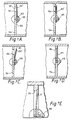
- Figure 7A to 7C illustrate different operating states of an exhaust modulator having a double reed valve adapted to provide stepped control;
- Figure 7D and 7E illustrate a single reed valve embodiment;
- Figure 8 is a block diagram of an exhaust modulator control system;
- In the following, various forms of the exhaust modulator according to this invention are described. All of the embodiments illustrated incorporate an exhaust modulator gate of the butterfly type but would equally apply to a sliding exhaust modulator gate.
- The exhaust modulator of Figures 3A to 3C comprises a butterfly-
type gate 44 mounted in an exhaust gas flow path through theexhaust modulator housing 10, on arotatable shaft 43 driven by an actuator (not shown) whereby thegate 44 can be opened or closed, to impose back pressure upon the engine when required for purposes of cab-heating or emission control or for exhaust braking. To limit the imposed back pressure two bleed-holes 46 are formed in thebutterfly gate 44, these being covered by strip-like reeds 41 and 41' attached to theshaft 43 by fixing screws or rivets 45, to prevent the flow of exhaust gas through thebleed holes 46 and thus causing back pressure to increase on the upstream side of thegate 44. - The
reeds 41 and 41' have different stiffnesses selected such that, thereed valve 41 opens to permit exhaust gas to flow downstream through thebleed hole 46 when the maximum desirable pressure level appropriate to the cab-heating or emission control operating mode (i.e. low engine speed/low exhaust gas flows) is reached. Reed 41', however, remains closed. - After use for this purpose, it is usual to operate the actuator (not shown) to open the gate, so that the engine continues to run in the usual manner.
- When exhaust braking is required, this normally occurring at high engine speeds and high exhaust gas flows, the actuator (not shown) is operated to close the gate and, as in the cab-heating mode, back pressure builds up but more rapidly. The
reed 41 will open almost as soon as the valve is closed, permitting limited leakage through thebleed hole 46 insufficient to prevent an increase in back pressure which further increases up to the desired maximum determined by the stiffness of the second reed 41' which then opens providing an increased effective bleed flow path area; the total of the cross-sectional areas of the twoholes 46. - The exhaust modulator of Figures 3A to 3C provides a stepped back pressure/engine exhaust gas flow profile enabling effective and efficient operation of the modulator, either in a cab-heating or emission control mode or in an exhaust brake mode as required.
- Figure 4 shows a similar modulator having two
reeds 61 and 61' of different stiffness but fitted withreed stops 67 and 67' respectively which can be set or adjusted as required to limit opening of the reed more than is desirable should the unit be fitted to an engine with an exhaust gas flow greater than the reed's design specification, or more importantly to limit the effective flow area of each bleed flowpath, enabling fine adjustment of the stepped characteristic or profile to suit a particular installation. - A sliding reed arrangement is used in the exhaust brake illustrated in Figures 5A to 5C. It has two
reeds 71 one of which is significantly stiffer than the other. Eachreed 71 and astrap 78 overlying thereed 71 are clamped at one end but the reed is allowed to slide relative to thestrap 78 by means of an open-ended slot in the reed at the other. Eachreed 71 covers two bleedholes 76 drilled in thebutterfly 74, and as the back pressure increases thereed 71 lifts towards the concave underside of thestrap 78 allowing exhaust gas to escape as illustrated in Figure 5B. - An alternative exhaust modulator valve arrangement shown in Figures 6A to 6C incorporates two
discs 81 each covering a singlebleed hole 86 and loaded by acoil spring 88 disposed within a housing attached to thebutterfly 84 for displacement therewith. Thedisc 81 seals against theseat 89 formed in thebutterfly valve 84. As the back pressure increases, thedisc 81 moves away from thebutterfly 84, allowing exhaust gas to escape downstream of the engine throughpassage 90. With increasing through flow of exhaust gas, thespring 88 becomes further compressed and the orifice area increases as shown in Figure 6B. - Operation of the embodiments of Figures 5A to 5C and Figures 6A to 6C, is, in principle, the same as for the embodiments of Figures 3A to 3C. Both provide a stepped back pressure characteristic or profile enabling use of the modulator in different operating modes without loss of efficiency.
- The exhaust brake of Figures 7A to 7C has two
reeds 101, and 101', which may be identical, separated by a spacer, the three parts fitting into aslot 102 in theshaft 103, and are secured by fixing screws or rivets 105. The thickness, stiffness and other characteristics of the reeds and spacer can be varied as appropriate for a particular application.Reed 101 lies flat against thebutterfly valve plate 104 coveringhole 106 as shown in Figure 7A preventing the escape of gas. As back pressure builds-upreed 101 deflects to open a bleed orifice which grows larger as the pressure increases to increase the exhaust gas through-flow, untilreed 101 comes into abutment with reed 101' so that the compound stiffness is then effective. It will be evident that this arrangement produces a change in the gradient of the back pressure/exhaust gas flow characteristic, at the point of abutment of the two reeds, so that further increases in back pressure give rise to slower increase in the size of the bleed orifice, producing a stepped or quasi-stepped response characteristic. If the reed 101' is significantly stiffer thanreed 101, the response will be substantially flat until the maximum back pressure in exhaust braking mode is reached. - In the single reed arrangement of Figures 7D and 7E, the
reed 111 is set centrally (of the cross-section) in thehole 116 in thebutterfly valve plate 114. On its downstream side the periphery of thehole 116 is partially countersunk as illustrated such that as the back pressure increases (Figure 7E) the size of the bleed orifice is increased continuously and more rapidly than the single reed arrangement shown in Figures 3A to 3C producing a less steeply curved back-pressure/exhaust gas flow characteristic. - One example of an 'external' control system for control of an exhaust modulator is shown in Figure 8. Detectors or sensors 121 for sensing various (in this case engine) operating parameters are connected to supply signals to a central control unit which may be a
computer 122 which in turn generates a control output signal to drive anactuator 124 for the exhaust brake via acontrol valve 125. The type of sensors 121 used will naturally depend upon the parameters to be monitored and the actuator may be of any conventional kind depending upon whether a butterfly or sliding exhaust brake gate is used. Mechanical, hydraulic, pneumatically, vacuum or solenoid operated, or indeed any suitable actuator may be used. It may be effective to control exhaust gas flow along the bleed flowpath(s) by adjustment of the effective flow area thereof in a manner analogous to the embodiments described above or may operate in response to a pulsed signal to relieve back pressure directly; effectively operating as a closed loop control system when (one of) the sensed parameter(s) is the back pressure applied to the engine.
Claims (11)
- An exhaust modulator in or to be fitted in the exhaust system of an engine, comprising a body (10) defining a flowpath therethrough for engine exhaust gases, a gate (24,44,64,74,84,104,114) in the exhaust flowpath movable between an open and a closed position, one or more bleed flowpaths (26,46,66,76,86,106,116) communicating between opposite sides of the gate, and flow control means operable to control the flow of exhaust gases along the said one or more bleed flowpaths so as to limit the back pressure applied to the engine to different predetermined levels, said flow control means comprising a closure valve having an aperture and a closure member (41,61,71,81,101,111) for the aperture, the closure member being urged into closing engagement with said aperture below a predetermined back pressure, and displaceable away from said aperture above said predetermined back pressure, characterised in that said one or more bleed flowpaths are formed in the gate.
- An exhaust modulator according to claim 1 in which the closure member comprises a reed or disc valve.
- An exhaust modulator according to claim 2 in which said closure valve comprises a reed valve (41,61,71,101,111).
- An exhaust modulator according to claim 3 in which said valve comprises a first reed valve (41,61,101) having a certain stiffness and a second reed valve (41',61',101') having a higher stiffness than the first reed valve.
- An exhaust modulator according to claim 4 in which the second reed valve (101') is arranged to control movement of the first reed valve (101).
- An exhaust modulator according to claim 4 in which a stop (67) is provided to limit movement of at least one of said reed valves (61,61').
- An exhaust modulator to claim 6 in which the stop is in the form of a strap (78) overlying said valve or valves.
- An exhaust modulator according to claim 2 in which said valve comprises a free disc (81) biased into closing engagement by a spring (88).
- An exhaust modulator according to claim 8 wherein said closure includes a plurality of orifices defining a plurality of bleed flowpaths and a plurality of discs one each biased towards a respective orifice to close the respective bleed flowpath, each disc being biased by resilient means of different stiffness, or pre-load.
- An exhaust modulator according to claim 9, in which different sized bleed flowpaths are provided.
- An exhaust modulator according to any preceding claim wherein said closure valve comprises part of said gate.
Applications Claiming Priority (3)
| Application Number | Priority Date | Filing Date | Title |
|---|---|---|---|
| GB909014486A GB9014486D0 (en) | 1990-06-29 | 1990-06-29 | Exhaust brake variable orifice |
| GB9014486 | 1990-06-29 | ||
| PCT/GB1991/001068 WO1992000445A1 (en) | 1990-06-29 | 1991-07-01 | An exhaust modulator |
Publications (2)
| Publication Number | Publication Date |
|---|---|
| EP0536284A1 EP0536284A1 (en) | 1993-04-14 |
| EP0536284B1 true EP0536284B1 (en) | 1995-10-25 |
Family
ID=10678415
Family Applications (1)
| Application Number | Title | Priority Date | Filing Date |
|---|---|---|---|
| EP91912782A Expired - Lifetime EP0536284B1 (en) | 1990-06-29 | 1991-07-01 | An exhaust modulator |
Country Status (7)
| Country | Link |
|---|---|
| US (1) | US5372109A (en) |
| EP (1) | EP0536284B1 (en) |
| JP (1) | JPH05507994A (en) |
| DE (1) | DE69114133T2 (en) |
| ES (1) | ES2077861T3 (en) |
| GB (1) | GB9014486D0 (en) |
| WO (1) | WO1992000445A1 (en) |
Families Citing this family (51)
| Publication number | Priority date | Publication date | Assignee | Title |
|---|---|---|---|---|
| FR2693505B1 (en) * | 1992-07-07 | 1994-09-09 | Centre Ntl Recherche Scient | Inlet or exhaust line for alternative machine. |
| JPH07243324A (en) * | 1994-03-02 | 1995-09-19 | Honda Motor Co Ltd | Exhaust gas purification device for internal combustion engine |
| US5445248A (en) * | 1994-03-07 | 1995-08-29 | Jenara Enterprises Ltd. | Exhaust brake |
| US5638926A (en) * | 1994-06-27 | 1997-06-17 | United States Gear Corporation | Vehicle engine brake |
| US5676110A (en) * | 1996-03-14 | 1997-10-14 | Meneely; Vincent Allan | Exhaust brake with offset butterfly and method of reducing back pressure therein |
| RU2119076C1 (en) * | 1996-07-11 | 1998-09-20 | Военный автомобильный институт | Internal combustion engine exhaust gas throttling device |
| KR19980063386A (en) * | 1996-12-26 | 1998-10-07 | 오니시 요시유키 | Actuator and exhaust brake device using same |
| JP3824375B2 (en) * | 1997-05-09 | 2006-09-20 | 日産ディーゼル工業株式会社 | Diesel engine control device |
| AT2107U3 (en) * | 1997-10-16 | 1999-03-25 | Avl List Gmbh | INTERNAL COMBUSTION ENGINE WITH AN ENGINE DUST BRAKE |
| AT1923U3 (en) * | 1997-05-14 | 1998-07-27 | Avl List Gmbh | INTERNAL COMBUSTION ENGINE WITH AN ENGINE DUST BRAKE |
| DE19821130B4 (en) * | 1997-05-14 | 2008-10-09 | Avl List Gmbh | Internal combustion engine with an engine dust brake |
| US6179096B1 (en) | 1997-11-12 | 2001-01-30 | Diesel Engine Retarders, Inc. | Exhaust brake variable bypass circuit |
| WO1999041495A1 (en) * | 1998-02-17 | 1999-08-19 | Diesel Engine Retarders, Inc. | Exhaust restriction device |
| FR2777945B1 (en) * | 1998-04-22 | 2000-06-16 | Fowa | SLOWDOWN DEVICE MOUNTED IN THE GAS EXHAUST CIRCUIT OF A VEHICLE EQUIPPED WITH A COMBUSTION ENGINE |
| FR2777946B1 (en) * | 1998-04-22 | 2000-06-16 | Fowa | SLOWDOWN DEVICE MOUNTED IN THE GAS EXHAUST CIRCUIT OF A VEHICLE EQUIPPED WITH A COMBUSTION ENGINE |
| JP3645864B2 (en) * | 2001-03-21 | 2005-05-11 | ダイムラークライスラー アーゲー | Equipment for noise configuration in motor vehicles |
| JP2003027930A (en) * | 2001-07-11 | 2003-01-29 | Komatsu Ltd | Exhaust gas purification device for internal combustion engine |
| DE10159362A1 (en) * | 2001-12-04 | 2003-06-18 | Visteon Global Tech Inc | Pressure control valve, especially for exhaust systems |
| US6662554B2 (en) | 2002-01-23 | 2003-12-16 | Deere & Company | Adjustable restriction muffler system for a combine |
| JP2004011602A (en) * | 2002-06-11 | 2004-01-15 | Aisan Ind Co Ltd | Exhaust pressure control valve |
| JP2004100516A (en) * | 2002-09-06 | 2004-04-02 | Mitsubishi Fuso Truck & Bus Corp | Failure detector of internal combustion engine |
| DE10251117A1 (en) * | 2002-11-02 | 2004-05-19 | Deutsche Montan Technologie Gmbh | Device to generate frequency spectrum in pipe in reciprocating piston engine has modified throttle plate with profiling and perforations to improve acoustic characteristics |
| US6899079B1 (en) * | 2003-07-03 | 2005-05-31 | Patrick George Hill | Engine exhaust brake |
| KR200340730Y1 (en) * | 2003-09-19 | 2004-02-11 | 유영배 | Car muffler |
| CA2453593C (en) | 2003-12-16 | 2013-05-28 | Jenara Enterprises Ltd. | Pressure relief exhaust brake |
| JP4130912B2 (en) | 2003-12-24 | 2008-08-13 | 愛三工業株式会社 | Exhaust pressure raising device for internal combustion engine |
| DE102004040820B4 (en) * | 2004-08-24 | 2009-03-19 | Pierburg Gmbh | Valve device |
| DE102004051627B4 (en) * | 2004-10-23 | 2010-07-01 | Pierburg Gmbh | Exhaust flap means |
| CN102094714B (en) * | 2004-11-22 | 2014-01-15 | 雅各布斯车辆系统公司 | Apparatus and method for controlling exhaust pressure |
| US7325569B2 (en) * | 2005-04-25 | 2008-02-05 | Honeywell International, Inc. | Butterfly valve with integral split flapper relief valve |
| EP2288878A1 (en) | 2008-05-16 | 2011-03-02 | Continental Automotive Systems US, Inc. | Pointer illumination |
| US7896128B2 (en) * | 2008-09-12 | 2011-03-01 | Theodore De Leo | Auto-sensing, automatic adjusting exhaust baffle |
| JP5359324B2 (en) * | 2009-01-30 | 2013-12-04 | 大豊工業株式会社 | Exhaust throttle valve for internal combustion engine |
| US7735466B1 (en) * | 2009-06-12 | 2010-06-15 | Jacobs Vehicle Systems, Inc. | Exhaust brake |
| JP5534144B2 (en) * | 2009-08-04 | 2014-06-25 | 大豊工業株式会社 | Exhaust throttle valve for internal combustion engine |
| JP5333271B2 (en) * | 2010-02-02 | 2013-11-06 | 株式会社デンソー | Intake valve device |
| AT510236B1 (en) * | 2010-07-26 | 2015-12-15 | MAN Truck & Bus Österreich AG | METHOD FOR MOTOR BRAKING |
| US20130291838A1 (en) * | 2012-05-04 | 2013-11-07 | Ronnie Lee Booth | Diesel bleeder |
| US20140251472A1 (en) * | 2013-03-06 | 2014-09-11 | J-Mac Tool, Inc. | Overpressurization Bypass for Fluid Valve |
| US20160076655A1 (en) * | 2013-04-24 | 2016-03-17 | International Engine Intellectual Property Company, Llc | Throttle valve having a pressure relief valve |
| US11554471B2 (en) * | 2014-08-28 | 2023-01-17 | Power Tech Staple and Nail, Inc. | Elastomeric exhaust reed valve for combustion driven fastener hand tool |
| KR101745068B1 (en) | 2015-01-30 | 2017-06-08 | 현대자동차주식회사 | Exhaust brake |
| CN107101024B (en) * | 2016-02-22 | 2020-07-07 | 浙江大自然户外用品股份有限公司 | Valve gate |
| DK178856B1 (en) | 2016-05-11 | 2017-04-03 | Oase Outdoors Aps | Valve for inflatable apparatuses |
| US10239599B1 (en) * | 2017-02-08 | 2019-03-26 | Brunswick Corporation | Stern drive arrangements having idle relief exhaust gas bypass |
| US11708785B2 (en) | 2017-10-04 | 2023-07-25 | Brc Engines Ip Pty Ltd. | Method of a controlled engine, engine and variants |
| WO2019068146A1 (en) * | 2017-10-04 | 2019-04-11 | Brc Engines Ip Pty Ltd | Method of a controlled engine, engine and variants |
| CN107762639A (en) * | 2017-11-22 | 2018-03-06 | 浙江博力机电制造有限公司 | A kind of new lever type exhaust brake valve |
| US10876644B2 (en) | 2018-05-22 | 2020-12-29 | Goodrich Corporation | Aspirator system pressure relief mechanism |
| US11105233B2 (en) | 2019-01-30 | 2021-08-31 | Toyota Motor North America, Inc. | Systems and methods for regulating performance characteristics of an exhaust system with a tri-modal valve |
| US11746685B2 (en) * | 2022-01-27 | 2023-09-05 | Ford Global Technologies, Llc | Exhaust restriction device for improved sensor signal |
Family Cites Families (12)
| Publication number | Priority date | Publication date | Assignee | Title |
|---|---|---|---|---|
| GB604777A (en) * | 1945-11-15 | 1948-07-09 | Brown David & Sons Ltd | Improved means for maintaining specified relations between two fluid pressures |
| AT233326B (en) * | 1962-07-12 | 1964-05-11 | Michael Guillermo Dipl Ing May | Method and device for reducing the proportions of unburned and partially burned constituents in the exhaust gases of externally ignited four-stroke internal combustion engines |
| SE372308B (en) * | 1972-12-29 | 1974-12-16 | Volvo Ab | |
| DE3529767A1 (en) * | 1975-09-06 | 1987-02-26 | Kloeckner Humboldt Deutz Ag | Engine brake device for an internal combustion engine |
| SU731003A2 (en) * | 1978-11-09 | 1980-04-30 | Предприятие П/Я М-5978 | Exhaust gas afterburner |
| DE2946747A1 (en) * | 1979-11-20 | 1981-05-27 | Daimler-Benz Ag, 7000 Stuttgart | MOTOR BRAKE FOR MOTOR VEHICLES |
| JPS58158333A (en) * | 1982-03-16 | 1983-09-20 | Amadera Kuatsu Kogyo Kk | Structure of exhaust brake valve |
| JPS59158350A (en) * | 1983-02-26 | 1984-09-07 | Hino Motors Ltd | Automatic control device for exhaust brake |
| DE3430028A1 (en) * | 1984-08-16 | 1986-02-27 | Alfred 8573 Pottenstein Schmidt | DEVICE FOR LIMITING THE EXHAUST PRESSURE OF AN EXHAUST ENGINE BRAKE |
| GB8425657D0 (en) * | 1984-10-10 | 1984-11-14 | Austin Rover Group | Exhaust system |
| DE3533393A1 (en) * | 1985-09-19 | 1987-03-26 | Alfred Schmidt | CONSTRUCTION PRESSURE LIMIT WITH SAFETY VALVE |
| SU1502866A1 (en) * | 1987-10-23 | 1989-08-23 | Центральный научно-исследовательский автомобильный и автомоторный институт | Apparatus for exhaust braking of ic-engine |
-
1990
- 1990-06-29 GB GB909014486A patent/GB9014486D0/en active Pending
-
1991
- 1991-07-01 JP JP91512011A patent/JPH05507994A/en active Pending
- 1991-07-01 US US07/962,188 patent/US5372109A/en not_active Expired - Lifetime
- 1991-07-01 DE DE69114133T patent/DE69114133T2/en not_active Expired - Fee Related
- 1991-07-01 EP EP91912782A patent/EP0536284B1/en not_active Expired - Lifetime
- 1991-07-01 ES ES91912782T patent/ES2077861T3/en not_active Expired - Lifetime
- 1991-07-01 WO PCT/GB1991/001068 patent/WO1992000445A1/en not_active Ceased
Also Published As
| Publication number | Publication date |
|---|---|
| EP0536284A1 (en) | 1993-04-14 |
| DE69114133T2 (en) | 1996-05-02 |
| US5372109A (en) | 1994-12-13 |
| WO1992000445A1 (en) | 1992-01-09 |
| ES2077861T3 (en) | 1995-12-01 |
| DE69114133D1 (en) | 1995-11-30 |
| JPH05507994A (en) | 1993-11-11 |
| GB9014486D0 (en) | 1990-08-22 |
Similar Documents
| Publication | Publication Date | Title |
|---|---|---|
| US5372109A (en) | Exhaust modulator | |
| US6179096B1 (en) | Exhaust brake variable bypass circuit | |
| US8011347B2 (en) | Apparatus and method for pressure relief in an exhaust brake | |
| CA1230978A (en) | Compressor bleed valve | |
| US6273058B1 (en) | Decelerator device mounted in the exhaust gas circuit of a vehicle equipped with a combustion engine | |
| US5394901A (en) | Exhaust pressure modulation valve | |
| WO1999041495A1 (en) | Exhaust restriction device | |
| JPH0214529B2 (en) | ||
| US4476682A (en) | Turbocharged internal combustion engine having an altitude compensated boost control and method for its operation | |
| US5065575A (en) | Air flow/check valve | |
| JPS58122354A (en) | Exhaust gas recirculation control device | |
| US4150646A (en) | EGR Control system for internal combustion engines | |
| JPS6034751Y2 (en) | supercharged engine | |
| JPH0953470A (en) | Exhaust brake device of diesel engine with turbocharger | |
| US4231336A (en) | Exhaust gas recirculation system for an internal combustion engine | |
| EP0578373B1 (en) | Exhaust brake and pressure modulation valve | |
| US4122808A (en) | Ignition timing control | |
| JP2690961B2 (en) | Pressure regulating valve | |
| JPS6367012B2 (en) | ||
| JPS6231656Y2 (en) | ||
| RU2050579C1 (en) | Gas pressure controller | |
| JPS5882030A (en) | Suction device for engine with supercharger | |
| GB2038416A (en) | Auxiliary Air Regulating Device for a Fuel Injection Internal Combustion Engine | |
| JPH0350369A (en) | Apparatus for controlling exhaustion rotary flow of diesel engine | |
| WO2001042712A1 (en) | Gas valve |
Legal Events
| Date | Code | Title | Description |
|---|---|---|---|
| PUAI | Public reference made under article 153(3) epc to a published international application that has entered the european phase |
Free format text: ORIGINAL CODE: 0009012 |
|
| 17P | Request for examination filed |
Effective date: 19930115 |
|
| AK | Designated contracting states |
Kind code of ref document: A1 Designated state(s): DE ES FR GB IT SE |
|
| 17Q | First examination report despatched |
Effective date: 19931207 |
|
| RAP1 | Party data changed (applicant data changed or rights of an application transferred) |
Owner name: WABCO AUTOMOTIVE U.K. LIMITED |
|
| GRAA | (expected) grant |
Free format text: ORIGINAL CODE: 0009210 |
|
| ITF | It: translation for a ep patent filed | ||
| AK | Designated contracting states |
Kind code of ref document: B1 Designated state(s): DE ES FR GB IT SE |
|
| ET | Fr: translation filed | ||
| REF | Corresponds to: |
Ref document number: 69114133 Country of ref document: DE Date of ref document: 19951130 |
|
| REG | Reference to a national code |
Ref country code: ES Ref legal event code: FG2A Ref document number: 2077861 Country of ref document: ES Kind code of ref document: T3 |
|
| PLBE | No opposition filed within time limit |
Free format text: ORIGINAL CODE: 0009261 |
|
| STAA | Information on the status of an ep patent application or granted ep patent |
Free format text: STATUS: NO OPPOSITION FILED WITHIN TIME LIMIT |
|
| 26N | No opposition filed | ||
| PGFP | Annual fee paid to national office [announced via postgrant information from national office to epo] |
Ref country code: SE Payment date: 19990610 Year of fee payment: 9 |
|
| PGFP | Annual fee paid to national office [announced via postgrant information from national office to epo] |
Ref country code: DE Payment date: 19990611 Year of fee payment: 9 |
|
| PGFP | Annual fee paid to national office [announced via postgrant information from national office to epo] |
Ref country code: GB Payment date: 19990618 Year of fee payment: 9 |
|
| PGFP | Annual fee paid to national office [announced via postgrant information from national office to epo] |
Ref country code: FR Payment date: 19990630 Year of fee payment: 9 |
|
| PGFP | Annual fee paid to national office [announced via postgrant information from national office to epo] |
Ref country code: ES Payment date: 19990708 Year of fee payment: 9 |
|
| PG25 | Lapsed in a contracting state [announced via postgrant information from national office to epo] |
Ref country code: GB Free format text: LAPSE BECAUSE OF NON-PAYMENT OF DUE FEES Effective date: 20000701 |
|
| PG25 | Lapsed in a contracting state [announced via postgrant information from national office to epo] |
Ref country code: SE Free format text: LAPSE BECAUSE OF NON-PAYMENT OF DUE FEES Effective date: 20000702 |
|
| PG25 | Lapsed in a contracting state [announced via postgrant information from national office to epo] |
Ref country code: ES Free format text: LAPSE BECAUSE OF NON-PAYMENT OF DUE FEES Effective date: 20000703 |
|
| GBPC | Gb: european patent ceased through non-payment of renewal fee |
Effective date: 20000701 |
|
| EUG | Se: european patent has lapsed |
Ref document number: 91912782.9 |
|
| PG25 | Lapsed in a contracting state [announced via postgrant information from national office to epo] |
Ref country code: FR Free format text: LAPSE BECAUSE OF NON-PAYMENT OF DUE FEES Effective date: 20010330 |
|
| REG | Reference to a national code |
Ref country code: FR Ref legal event code: ST |
|
| PG25 | Lapsed in a contracting state [announced via postgrant information from national office to epo] |
Ref country code: DE Free format text: LAPSE BECAUSE OF NON-PAYMENT OF DUE FEES Effective date: 20010501 |
|
| REG | Reference to a national code |
Ref country code: ES Ref legal event code: FD2A Effective date: 20020603 |
|
| PG25 | Lapsed in a contracting state [announced via postgrant information from national office to epo] |
Ref country code: IT Free format text: LAPSE BECAUSE OF NON-PAYMENT OF DUE FEES;WARNING: LAPSES OF ITALIAN PATENTS WITH EFFECTIVE DATE BEFORE 2007 MAY HAVE OCCURRED AT ANY TIME BEFORE 2007. THE CORRECT EFFECTIVE DATE MAY BE DIFFERENT FROM THE ONE RECORDED. Effective date: 20050701 |