JP2004011602A - Exhaust pressure control valve - Google Patents
Exhaust pressure control valve Download PDFInfo
- Publication number
- JP2004011602A JP2004011602A JP2002169881A JP2002169881A JP2004011602A JP 2004011602 A JP2004011602 A JP 2004011602A JP 2002169881 A JP2002169881 A JP 2002169881A JP 2002169881 A JP2002169881 A JP 2002169881A JP 2004011602 A JP2004011602 A JP 2004011602A
- Authority
- JP
- Japan
- Prior art keywords
- relief valve
- relief
- valve body
- valve
- chamber
- Prior art date
- Legal status (The legal status is an assumption and is not a legal conclusion. Google has not performed a legal analysis and makes no representation as to the accuracy of the status listed.)
- Pending
Links
Images


Classifications
-
- F—MECHANICAL ENGINEERING; LIGHTING; HEATING; WEAPONS; BLASTING
- F02—COMBUSTION ENGINES; HOT-GAS OR COMBUSTION-PRODUCT ENGINE PLANTS
- F02D—CONTROLLING COMBUSTION ENGINES
- F02D9/00—Controlling engines by throttling air or fuel-and-air induction conduits or exhaust conduits
- F02D9/04—Controlling engines by throttling air or fuel-and-air induction conduits or exhaust conduits concerning exhaust conduits
- F02D9/06—Exhaust brakes
Abstract
Description
【0001】
【発明の属する技術分野】
本発明は、主通路とバイパス通路とを備え、主通路に絞り弁が配置されるとともに、バイパス通路に流入する流体の圧力を調整するリリーフ弁を備えた排気圧力制御弁に関する。
【0002】
【従来の技術】
従来、リリーフ弁を備えた排気圧力制御弁は、エンジンの排気弁の損傷を防止するために、圧力が高くなりすぎた排気ガスの一部をブレーキ弁の上流側からバイパス通路を通して下流側に逃がすように構成されていた。この際、リリーフ弁体と対向するように配置されたリリーフ弁座はバルブボディの一部として一体的に形成されていた。バルブボディは、通常、球状黒鉛鋳鉄で形成されていることから、リリーフ弁座の耐食性を向上することができず、主通路あるいはバイパス通路を流れる酸性凝縮水によって腐食しやすい。リリーフ弁座が腐食すると、リリーフ弁体とリリーフ弁座とが固着して作動不能を発生してしまう。
【0003】
このために、特開平9−144569号に示すように、リリーフ弁座に硬度を付加して耐摩耗性を向上することができるように、リリーフ弁座をバルブボディと別体で構成する排気ブレーキ装置が提供されていた。
【0004】
この排気ブレーキ装置50によると、図5に示すように、リリーフ弁60は、排気ブレーキ弁51のブレーキボディ52と別体で構成され、リリーフ弁60に、排気ブレーキ弁51のバイパス通路61を形成するように装着されている。
【0005】
リリーフ弁60には、リリーフボディ62と別体で形成されるとともにリリーフ弁座63aを有するシート部材63と、リリーフ弁座63aに向かって接近離隔する方向に移動するリリーフ弁体64とを備えるリリーフ弁室65と、リリーフ弁室65に装着するリリーフばね室67とを備えて構成されている。リリーフばね室67には、リリーフ弁体64をリリーフ弁座63a側に向かって付勢するリリーフばね68が内蔵されている。
【0006】
そして、シート部材63を間にして配置される流入口61aと流出口61bとを、ガスケット55を介してブレーキボディ52の流入口53aと流出口53bとに対向するように配置して、リリーフ弁60を排気ブレーキ弁51に装着する。この構成によって、単体で形成されるシート部材63に硬度を付与して硬度を高めることができ、リリーフ弁座63aの摩耗を防止することができるようになった。
【0007】
【発明が解決しようとする課題】
しかし、上記に示す公報における従来の排気ブレーキ装置50では、リリーフ弁60がブレーキ弁51と別体で構成されていることから、排気ブレーキ装置50自体が複雑になるとともに、リリーフ弁60の取付けスペースを広く取ることとなっていた。また、リリーフ弁60がリリーフ弁室65とリリーフばね室67とに分割され、さらにリリーフ弁室65はリリーフボディ62の中央部の突出壁部62aを間にして弁室65aとシール室65bとに分かれて構成されている。
【0008】
そして、それぞれの室に配置される各部位が、それぞれの開口部から挿入されて組み付けられていることから、例えば、リリーフ弁室65にリリーフ弁体64とシート部材63を組み付ける際、リリーフ弁体64とシート部材22を弁室65aの左開口部、つまり、図中、リリーフ弁室65の左方向から弁室65a内に挿入し、シール部材66はシール室65bの右開口部、つまり、図中リリーフ弁室65の右方向からシール室65b内に挿入していた。
【0009】
また、リリーフばね室67にリリーフばね68を組み付ける際、リリーフばね68をリリーフばね室67の左開口部、つまり、図中、左方向からリリーフばね室67内に挿入することになって、各室に各部位をそれぞれ異なる方向から組み付けることとなっていた。
【0010】
従って、組付性が悪いことから組付時間に手間が掛かり組付コストを増大させていた。しかも、リリーフ弁室65にシート部材63を挿入する際、シート部材63を弁室65aの左開口部から挿入することから、左方向に付勢するリリーフばね68でリリーフ弁体64を左方向に押圧することとなって、シート部材63をリリーフボディ62から脱落させる方向に組み付けることとなっていた。
【0011】
本発明は、上述の課題を解決するものであり、リリーフ弁体やシート部材、あるいはリリーフばねを同時に同方向から組み付けて組付時間を短縮するとともにコンパクトに構成し、また、シート部材のボディからの脱落を防止でき、さらに、シート部材の腐食を防止できる排気圧力制御弁を提供することを目的とする。
【0012】
【課題を解決するための手段】
本発明に係る排気圧力制御弁は、上記の課題を解決するために、以下のように構成するものである。すなわち、
バルブボディ内で絞り弁が配置された主通路と、前記絞り弁を回避して配置されるバイパス通路とを備える排気圧力制御弁であって、
前記バイパス通路には、前記主通路から流入する流体の圧力を調整するリリーフ弁室が前記バルブボディと一体的に形成され、
前記リリーフ弁室には、少なくともリリーフ弁体と、前記バルブボディと別体で形成されるとともに前記リリーフ弁体に当接可能なリリーフ弁座を有して前記バルブボディに配置されるシート部材と、前記リリーフ弁体を摺動可能に案内するリリーフ弁体摺動ガイドと、前記リリーフ弁体を前記リリーフ弁座側に付勢するリリーフばねとが配置されるとともに、少なくとも前記リリーフ弁体、前記シート部材、前記リリーフ弁体摺動ガイド、前記リリーフばねが、前記リリーフ弁室に同一方向から挿入できるように前記リリーフ弁室が構成されていることを特徴とするものである。
【0013】
また好ましくは、前記シート部材が、高耐食性を有して形成されていればよい。
【0014】
さらに、この発明にかかわる排気圧力制御弁は、バルブボディ内で絞り弁が配置された主通路と、前記絞り弁を回避して配置されるバイパス通路とを備えるものであって、
前記バイパス通路には、前記主通路から流入する流体の圧力を調整するリリーフ弁室が形成され、前記リリーフ弁室には、前記リリーフ弁室内を摺動可能なリリーフ弁体と、前記リリーフ弁体に当接可能なシート部材とが配置され、前記シート部材が高耐食性を有して形成されていることを特徴とするものである。
【0015】
【発明の効果】
本発明の排気圧力制御弁によれば、バルブボディに一体的に形成されたリリーフ弁室に、少なくともシート部材、リリーフ弁体、リリーフ弁体ガイド、リリーフばねが順次あるいはセットで挿入することができることから、組付時間を大幅に短縮することができる。
【0016】
しかも、シート部材が、バルブボディと別体で形成してバルブボディに装着することができることから、シート部材を高耐食性からなる材料、あるいは、リリーフ弁座に高耐食性を有して形成する材料で構成することができる。これによって、リリーフ弁座が腐食することを防止できるとともに、シート部材を別体で形成することによって、高耐食性を有する材料でバルブボディ全体でなくシート部材だけを形成できることから低コストで製作することが可能となる。
【0017】
さらに、排気圧力制御弁は、バイパス通路に、摺動可能なリリーフ弁体とリリーフ弁体に当接可能なシート部材とが配置されリリーフ弁室が設けられているものであれば、シート部材を高耐食性を有して形成することによって、シート部材が腐食するのを防止でき、耐久性を向上した排気圧力制御弁を提供することができる。
【0018】
【発明の実施の形態】
以下、本発明の一実施形態を図面に基づいて説明する。
【0019】
実施形態の排気圧力制御弁(以下、制御弁という)1は、図1に示すように、エンジン2から排出側に配管される排気管3の中間経路中に配置され、排気ガスの通る主通路5を開閉するように絞り弁6を備えている。絞り弁6は、電磁弁7及びアクチュエータ8によって軸を中心に回動され、管3内径との隙間の量によって上流側5aから下流側5bに流れる排気ガスの排気量を制御している。
【0020】
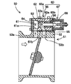
排気管3に配置される実施形態の制御弁1を詳細に説明すると、制御弁1は、図2に示すように、主通路5と、主通路5を内蔵するバルブボディ11と、電磁弁7の駆動で主通路5を開閉可能に配置する絞り弁6と、絞り弁6を間にして主通路の上流側(図1中、左側)5aに形成する流入口13と下流側5bに形成する流出口14及び流入口13・流出口14に連接するバイパス路15とで形成されるバイパス通路12と、バイパス通路12の流入口13を開閉可能に配置するリリーフ弁室20と、を備えて構成されている。
【0021】
リリーフ弁室20は、リリーフボディ21がバルブボディ11と一体的に形成されるとともに、リリーフボディ21が、主通路5に対して直交する方向に突出して形成されている。
【0022】
リリーフ弁室20には、バイパス通路12の流入口13に対向して、バルブボディ11の外周面側に装着するシート部材22と、シート部材22に接近離隔する方向に摺動するリリーフ弁体23と、リリーフ弁体23の摺動を案内支持するリリーフ弁体摺動ガイド24と、リリーフ弁体23をシート部材22側に付勢するリリーフばね25と、リリーフばね25の一端側を支持してリリーフ弁室20に螺合するプラグ26とが配置されている。
【0023】
バルブボディ11は、外径略矩形状に形成されるとともに鋳鋼等で形成され、主通路5は丸孔に形成され、リリーフボディ21は円筒状に形成されてリリーフ弁室20を構成することとなる。
【0024】
絞り弁6は、円板状に形成され、軸心部が主通路を横断するシャフト6aで支持されている。シャフト6aは電磁弁7によって駆動されるアクチュエータ8に接続されている。そして、アクチュエータ8の作動により、絞り弁6がシャフト6aを中心にして回動され、排気管3の内径との間に所定量の隙間を形成可能とする。
【0025】
リリーフ弁室20は、内部を段つき丸孔状に形成して下部の小径部20aと上部の大径部20bとに形成している。小径部20aには、リリーフ弁体23の弁部23bが収納され、大径部20bにはリリーフ弁体摺動ガイド24が圧入状態で下端部を小径部20aとの段差面に当接して配置されている。さらに、大径部20bの上部には、雌ねじ20cが形成され、プラグ26を螺合している。
【0026】
シート部材22はリング状に形成され、耐食性を向上するために、実施形態では、ステンレス材(SUS430等)で形成している。なお、シート部材22は、耐食性が高いものであれば、ステンレス材に限定するものではなく、また、例えば、炭素鋼で形成したもので表面を耐食性の薄膜材料でコーティングしたものであってもよい。
【0027】
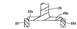
そして、図3に示すように、シート部材22の一端面には、内径部の周縁部にテーパ状のリリーフ弁座22aが形成されている。リリーフ弁座22aは、リリーフ弁体23に対向して配置され、リリーフ弁体23先端部が当接可能に形成される。そして、リリーフ弁体23の先端部がリリーフ弁座22aに当接することによって流入口13を閉鎖し、リリーフ弁体23が離れることによって、排気ガスの一部がバイパス通路12に流入できるように構成される。
【0028】
リリーフ弁体23は、図2に示すように、リリーフ弁体摺動ガイドに摺動案内される摺動部23aと摺動部23aから突出して形成される弁部23bとを有し、摺動部23aと弁部23bとの間には小径状の連結部23cで接続されている。連結部23cの周りはバイパス路15と連通され、弁部23bの先端には、シート部材22のリリーフ弁座22aに係合可能なテーパ部23d(図3参照)を備えている。また、摺動部の後端部には、リリーフばね25の一端を挿入可能な凹部23eが形成されている。
【0029】
次に、上記のように構成されたリリーフ弁室20の組付方法について説明する。リリーフ弁室20内に各部位を挿入する前は、リリーフ弁室20内は中空状に形成されて上部が開口されている。図4に示すように、まず、シート部材22を、リリーフ弁座22aを上方に向けた状態で、リリーフ弁室20の上部開口部20dからリリーフ弁室20内に挿入し、バルブボディ11のバイパス路5端面側に形成されたシート部材挿入凹部11aに圧入状態で嵌合させる。シート部材22は、流体の圧力でバルブボディ11から脱落しないように、シート部材22の内周面は、流入口13の内径と略同一の寸法に形成されていることが望ましい。
【0030】
次に、リリーフ弁体摺動ガイド24にリリーフ弁体23を嵌め込み、プラグ26に一端を挿入したリリーフばね25の他端をリリーフ弁体23の凹部23eに嵌入させて1セットとした状態で、リリーフ弁室20内に上部開口部20dから挿入する。この際、リリーフ弁体摺動ガイド24をリリーフ弁室20の大径部20bに圧入して挿入するとともに、リリーフ弁摺動ガイド24の先端面をリリーフ弁室20の小径部20aとの段差面に当接して固定する。
【0031】
そして、プラグ26をリリーフ弁室20の雌ねじ20cに螺合してリリーフ弁室20の上部を閉口する。この際、バイパス通路12を通る流体の設定圧力に対向して、リリーフばね25のリリーフ弁体23に付与する付勢力を設定する。これは、プラグ26の締め込み具合によって設定される。
【0032】
なお、リリーフ弁室20内に各部位を挿入する際、シート部材22以外の各部位を1部品ごと挿入するようにしてもよい。いずれも、リリーフ弁室20の上部開口部20dより挿入することとなる。
【0033】
次に、上記のように組み付けられた制御弁1の作用について図1〜3に基づいて説明する。
【0034】
通常時において、エンジンから排気された排気ガスは、主通路5の上流側5aから、絞り弁6と排気管3の内周面との隙間から下流側5bに流れて外部に排出される。この状態では、リリーフ弁体23は、リリーフばね25の付勢力により、リリーフ弁座22aを押圧し、流入口13を塞いでいる。
【0035】
そして、絞り弁6が排気管3の内周面を塞いだ状態、あるいは絞り弁6と排気管3の内周面との設定された隙間量で絞り弁6が傾斜している状態で設定以上の高圧が上流側に掛けられたとき、例えば、排気ブレーキ作用や暖機運転中において、エンジンの高速回転により、上流側5aの圧力が上昇すると、上流側5aの排気ガスが、リリーフ弁体23を押圧する。この押圧力が、リリーフばね25のリリーフ弁体23に付与する付勢力に打ち勝つと、リリーフ弁体23は、リリーフ弁座22aに当接している状態から離れて流入口13を開口する。圧力の上昇した排気ガスは流入口13からバイパス路15を通って流出口14から下流側5bに流れることとなる。これによって、排気ガスは、エンジンが高回転になったとしても、適宜、バイパス通路12を通って外部に排出されることから、排気管内において高圧状態を回避できることから、エンジン2の排気弁2aを損傷させない。
【0036】
上述のように、実施形態の制御弁1では、リリーフ弁室20内にリリーフ弁体23等の部品を組み付ける際に、リリーフ弁室20の上部開口部20dより、シート部材22、リリーフ弁体23、リリーフ弁体摺動ガイド24、リリーフばね25、プラグ26を、順次あるいは同時に挿入して組み付けることができることから、組付性を向上することができ、極めて短時間で組み付けすることができる。従って、組付コストを低減して、コスト低減された制御弁1を提供することが可能となる。
【0037】
しかも、シート部材22はバルブボディ11と別体で形成することから、シート部材22を高耐食性に形成することができる。つまり、シート部材22をステンレス材で形成したり、また、シート部材22に薄膜コーティングを施したりすることを容易に行なうことができる。シート部材22を高耐食性に形成することによって、シート部材22の腐食を防止して耐久性のある制御弁1を提供することができる。このことは、シート部材22を高耐食性に形成するだけでよいことから、バルブボディ11全体を高耐食性に形成する必要はなく、低コストで製作することができる。
【0038】
なお、シート部材を高耐食性に形成することに関しては、リリーフ弁体とシート部材とを含めてリリーフ弁室を構成するものであれば、上記の形態の制御弁1に限定するものではない。
【0039】
また、シート部材22は、リリーフばね25の付勢力が作用する方向に、バルブボディ11に位置規制されて装着していることから、リリーフばね25の付勢力によって、バルブボディ11から脱落することがなく安定した作用を行なうことができる。
【図面の簡単な説明】
【図1】エンジンと排気圧力制御弁との配置関係を示す概略構成図である。
【図2】本発明の一形態の排気圧力制御弁を示す断面図である。
【図3】図2におけるリリーフ弁体とリリーフ弁座を示す要部拡大図である。
【図4】リリーフ弁室に各部位を挿入する状態を示す分解図である。
【図5】従来の排気ブレーキ装置を示す断面図である。
【符号の説明】
1 排気圧力制御弁
2 エンジン
3 排気管
5 主通路
5a 上流側
5b 下流側
11 バルブボディ
12 バイパス通路
13 流入口
20 リリーフ弁室
22 シート部材
22a リリーフ弁座
23 リリーフ弁体
24 リリーフ弁体摺動ガイド
25 リリーフばね[0001]
TECHNICAL FIELD OF THE INVENTION
The present invention relates to an exhaust pressure control valve including a main passage and a bypass passage, a throttle valve disposed in the main passage, and a relief valve for adjusting a pressure of a fluid flowing into the bypass passage.
[0002]
[Prior art]
Conventionally, an exhaust pressure control valve provided with a relief valve allows a part of exhaust gas having an excessively high pressure to escape from an upstream side of a brake valve to a downstream side through a bypass passage in order to prevent damage to an exhaust valve of an engine. Was configured as follows. At this time, the relief valve seat arranged so as to face the relief valve body was integrally formed as a part of the valve body. Since the valve body is usually formed of spheroidal graphite cast iron, the corrosion resistance of the relief valve seat cannot be improved, and the valve body is easily corroded by acidic condensed water flowing through the main passage or the bypass passage. If the relief valve seat is corroded, the relief valve body and the relief valve seat stick to each other, causing inoperability.
[0003]
For this purpose, as disclosed in Japanese Patent Application Laid-Open No. 9-144569, an exhaust brake in which the relief valve seat is formed separately from the valve body so that the relief valve seat can be hardened to improve wear resistance. Equipment was provided.
[0004]
According to the
[0005]
The
[0006]
An
[0007]
[Problems to be solved by the invention]
However, in the conventional
[0008]
And since each part arrange | positioned in each chamber is inserted and assembled | attached from each opening part, for example, when assembling the
[0009]
When assembling the
[0010]
Therefore, since the assembling property is poor, the assembling time is troublesome and the assembling cost is increased. Moreover, when the
[0011]
The present invention has been made to solve the above-described problems, and a relief valve element, a seat member, or a relief spring is simultaneously assembled from the same direction to shorten the assembly time and to be compact. It is an object of the present invention to provide an exhaust pressure control valve which can prevent the falling off of the seat member and can prevent the corrosion of the seat member.
[0012]
[Means for Solving the Problems]
An exhaust pressure control valve according to the present invention is configured as follows in order to solve the above-mentioned problems. That is,
An exhaust pressure control valve including a main passage in which a throttle valve is arranged in a valve body, and a bypass passage arranged to avoid the throttle valve,
In the bypass passage, a relief valve chamber for adjusting the pressure of the fluid flowing from the main passage is formed integrally with the valve body,
In the relief valve chamber, at least a relief valve body, a seat member formed separately from the valve body and having a relief valve seat that can abut on the relief valve body and disposed on the valve body. A relief valve sliding guide for slidably guiding the relief valve, and a relief spring for urging the relief valve toward the relief valve seat side are arranged, and at least the relief valve, The relief valve chamber is configured such that a seat member, the relief valve body sliding guide, and the relief spring can be inserted into the relief valve chamber from the same direction.
[0013]
More preferably, the sheet member may be formed with high corrosion resistance.
[0014]
Further, the exhaust pressure control valve according to the present invention includes a main passage in which a throttle valve is arranged in a valve body, and a bypass passage arranged to bypass the throttle valve,
A relief valve chamber for adjusting the pressure of the fluid flowing from the main passage is formed in the bypass passage. The relief valve chamber has a relief valve body slidable in the relief valve chamber, and a relief valve body. And a sheet member capable of contacting the sheet member, and the sheet member is formed with high corrosion resistance.
[0015]
【The invention's effect】
According to the exhaust pressure control valve of the present invention, at least the seat member, the relief valve body, the relief valve body guide, and the relief spring can be sequentially or collectively inserted into the relief valve chamber integrally formed with the valve body. Therefore, the assembling time can be greatly reduced.
[0016]
Moreover, since the seat member can be formed separately from the valve body and attached to the valve body, the seat member is made of a material having high corrosion resistance or a material formed with high corrosion resistance on the relief valve seat. Can be configured. Accordingly, the relief valve seat can be prevented from being corroded, and the seat member is formed separately, so that only the seat member can be formed from a material having high corrosion resistance, instead of the entire valve body. Becomes possible.
[0017]
Furthermore, if the exhaust pressure control valve is provided with a relief valve chamber provided with a slidable relief valve body and a seat member capable of contacting the relief valve body in the bypass passage, the seat member may be replaced by a seat member. By forming with high corrosion resistance, corrosion of the sheet member can be prevented, and an exhaust pressure control valve with improved durability can be provided.
[0018]
BEST MODE FOR CARRYING OUT THE INVENTION
Hereinafter, an embodiment of the present invention will be described with reference to the drawings.
[0019]
As shown in FIG. 1, an exhaust pressure control valve (hereinafter, referred to as a control valve) 1 of the embodiment is disposed in an intermediate path of an exhaust pipe 3 that is piped from an
[0020]
The
[0021]
In the
[0022]
The
[0023]
The
[0024]
The
[0025]
The inside of the
[0026]
The
[0027]
As shown in FIG. 3, a tapered
[0028]
As shown in FIG. 2, the
[0029]
Next, a method of assembling the
[0030]
Next, the
[0031]
Then, the
[0032]
When each part is inserted into the
[0033]
Next, the operation of the
[0034]
In normal times, the exhaust gas exhausted from the engine flows from the
[0035]
In the state where the
[0036]
As described above, in the
[0037]
Moreover, since the
[0038]
The formation of the seat member with high corrosion resistance is not limited to the above-described
[0039]
Further, since the
[Brief description of the drawings]
FIG. 1 is a schematic configuration diagram showing an arrangement relationship between an engine and an exhaust pressure control valve.
FIG. 2 is a cross-sectional view illustrating an exhaust pressure control valve according to one embodiment of the present invention.
FIG. 3 is an enlarged view of a main part showing a relief valve body and a relief valve seat in FIG. 2;
FIG. 4 is an exploded view showing a state where each part is inserted into a relief valve chamber.
FIG. 5 is a sectional view showing a conventional exhaust brake device.
[Explanation of symbols]
Claims (3)
前記バイパス通路には、前記主通路から流入する流体の圧力を調整するリリーフ弁室が前記バルブボディと一体的に形成され、
前記リリーフ弁室には、少なくともリリーフ弁体と、前記バルブボディと別体で形成されるとともに前記リリーフ弁体に当接可能なリリーフ弁座を有して前記バルブボディに配置されるシート部材と、前記リリーフ弁体を摺動可能に案内するリリーフ弁体摺動ガイドと、前記リリーフ弁体を前記リリーフ弁座側に付勢するリリーフばねとが配置されるとともに、少なくとも前記リリーフ弁体、前記シート部材、前記リリーフ弁体摺動ガイド、前記リリーフばねが、前記リリーフ弁室に同一方向から挿入できるように前記リリーフ弁室が構成されていることを特徴とする排気圧力制御弁。An exhaust pressure control valve including a main passage in which a throttle valve is arranged in a valve body, and a bypass passage arranged to bypass the throttle valve,
In the bypass passage, a relief valve chamber for adjusting the pressure of the fluid flowing from the main passage is formed integrally with the valve body,
In the relief valve chamber, at least a relief valve body, a seat member formed separately from the valve body and having a relief valve seat capable of abutting on the relief valve body and disposed on the valve body. A relief valve sliding guide for slidably guiding the relief valve, and a relief spring for urging the relief valve toward the relief valve seat side are arranged, and at least the relief valve, An exhaust pressure control valve, wherein the relief valve chamber is configured so that a seat member, the relief valve body sliding guide, and the relief spring can be inserted into the relief valve chamber from the same direction.
前記バイパス通路には、前記主通路から流入する流体の圧力を調整するリリーフ弁室が形成され、
前記リリーフ弁室には、前記リリーフ弁室内を摺動可能なリリーフ弁体と、前記リリーフ弁体に当接可能なシート部材とが配置され、
前記シート部材が高耐食性を有して形成されていることを特徴とする排気圧力制御弁。An exhaust pressure control valve including a main passage in which a throttle valve is arranged in a valve body, and a bypass passage arranged to bypass the throttle valve,
In the bypass passage, a relief valve chamber for adjusting the pressure of the fluid flowing from the main passage is formed,
In the relief valve chamber, a relief valve body slidable in the relief valve chamber, and a seat member capable of contacting the relief valve body are arranged,
An exhaust pressure control valve, wherein the seat member is formed with high corrosion resistance.
Priority Applications (2)
| Application Number | Priority Date | Filing Date | Title |
|---|---|---|---|
| JP2002169881A JP2004011602A (en) | 2002-06-11 | 2002-06-11 | Exhaust pressure control valve |
| EP03010205A EP1371831A1 (en) | 2002-06-11 | 2003-05-06 | Exhaust pressure control valve |
Applications Claiming Priority (1)
| Application Number | Priority Date | Filing Date | Title |
|---|---|---|---|
| JP2002169881A JP2004011602A (en) | 2002-06-11 | 2002-06-11 | Exhaust pressure control valve |
Publications (1)
| Publication Number | Publication Date |
|---|---|
| JP2004011602A true JP2004011602A (en) | 2004-01-15 |
Family
ID=29561743
Family Applications (1)
| Application Number | Title | Priority Date | Filing Date |
|---|---|---|---|
| JP2002169881A Pending JP2004011602A (en) | 2002-06-11 | 2002-06-11 | Exhaust pressure control valve |
Country Status (2)
| Country | Link |
|---|---|
| EP (1) | EP1371831A1 (en) |
| JP (1) | JP2004011602A (en) |
Cited By (1)
| Publication number | Priority date | Publication date | Assignee | Title |
|---|---|---|---|---|
| CN103233823A (en) * | 2013-04-28 | 2013-08-07 | 深圳市特尔佳科技股份有限公司 | Constant-pressure exhaust braking method and constant-pressure exhaust braking butterfly valve |
Families Citing this family (6)
| Publication number | Priority date | Publication date | Assignee | Title |
|---|---|---|---|---|
| JP4130912B2 (en) * | 2003-12-24 | 2008-08-13 | 愛三工業株式会社 | Exhaust pressure raising device for internal combustion engine |
| DE102012200029B4 (en) * | 2012-01-03 | 2018-12-20 | Ford Global Technologies, Llc | Protection system for a motor |
| US9482148B2 (en) | 2013-11-06 | 2016-11-01 | Ford Global Technologies, Llc | Active exhaust pulse management |
| CN107762639A (en) * | 2017-11-22 | 2018-03-06 | 浙江博力机电制造有限公司 | A kind of new lever type exhaust brake valve |
| CN108223859B (en) * | 2017-12-06 | 2019-09-27 | 潍柴动力股份有限公司 | Mechanical vent valve and engine for engine |
| JP6933591B2 (en) * | 2018-02-23 | 2021-09-08 | 株式会社ミクニ | Throttle device and fuel evaporative emission recovery system |
Family Cites Families (4)
| Publication number | Priority date | Publication date | Assignee | Title |
|---|---|---|---|---|
| DE3533393A1 (en) * | 1985-09-19 | 1987-03-26 | Alfred Schmidt | CONSTRUCTION PRESSURE LIMIT WITH SAFETY VALVE |
| GB9014486D0 (en) * | 1990-06-29 | 1990-08-22 | Dewandre Co Ltd C | Exhaust brake variable orifice |
| US6109027A (en) * | 1998-02-17 | 2000-08-29 | Diesel Engine Retarders, Inc. | Exhaust restriction device |
| FR2777946B1 (en) * | 1998-04-22 | 2000-06-16 | Fowa | SLOWDOWN DEVICE MOUNTED IN THE GAS EXHAUST CIRCUIT OF A VEHICLE EQUIPPED WITH A COMBUSTION ENGINE |
-
2002
- 2002-06-11 JP JP2002169881A patent/JP2004011602A/en active Pending
-
2003
- 2003-05-06 EP EP03010205A patent/EP1371831A1/en not_active Withdrawn
Cited By (1)
| Publication number | Priority date | Publication date | Assignee | Title |
|---|---|---|---|---|
| CN103233823A (en) * | 2013-04-28 | 2013-08-07 | 深圳市特尔佳科技股份有限公司 | Constant-pressure exhaust braking method and constant-pressure exhaust braking butterfly valve |
Also Published As
| Publication number | Publication date |
|---|---|
| EP1371831A1 (en) | 2003-12-17 |
Similar Documents
| Publication | Publication Date | Title |
|---|---|---|
| US9453438B2 (en) | Valve timing adjusting device | |
| US20050011703A1 (en) | Oil passage switching valve having oil filter | |
| JP3307919B2 (en) | Valve device for fluid piping | |
| US20080121480A1 (en) | Ejector and negative pressure supply apparatus for brake booster using the ejector | |
| WO2016031564A1 (en) | Variable flow valve mechanism and supercharger | |
| JP2005256836A (en) | Two-piece elastomer relief valve for filter and anti-drain back valve | |
| JP5137285B2 (en) | Valve flapper having a peripheral seal for movement | |
| JP2006348894A (en) | Twin scroll turbine housing for turbocharger | |
| JPH11229886A (en) | Turbocharger sealing unit | |
| JP2004011602A (en) | Exhaust pressure control valve | |
| EP1975482A1 (en) | Check valve for a compressor | |
| JP2004138065A5 (en) | ||
| JP4428501B2 (en) | Check valve | |
| JPH09144569A (en) | Exhaust brake device | |
| US20150000273A1 (en) | Turbocharger with annular rotary bypass valve for the turbine, and catalyst disposed in the bypass channel of the turbine housing | |
| JP2007198279A (en) | Composite valve, and blowby gas reducing device of engine equipped with composite valve | |
| JP2003522884A (en) | Control device for positive displacement pump | |
| EA200602171A1 (en) | AIR CONDITIONING DEVICE | |
| JPH11343857A (en) | Actuator for turbocharger | |
| JP2005113718A (en) | Bypass intake air quantity control device | |
| JP3577432B2 (en) | Check valve | |
| JP2969444B2 (en) | Dual plate check valve | |
| JPH05156920A (en) | Muffler for internal combustion engine | |
| JP2005256765A (en) | Exhaust control device for internal combustion engine | |
| JPH04339103A (en) | Seal fin clearance adjusting device |
Legal Events
| Date | Code | Title | Description |
|---|---|---|---|
| A621 | Written request for application examination |
Effective date: 20040721 Free format text: JAPANESE INTERMEDIATE CODE: A621 |
|
| A131 | Notification of reasons for refusal |
Effective date: 20070515 Free format text: JAPANESE INTERMEDIATE CODE: A131 |
|
| A521 | Written amendment |
Effective date: 20070710 Free format text: JAPANESE INTERMEDIATE CODE: A523 |
|
| A131 | Notification of reasons for refusal |
Effective date: 20071023 Free format text: JAPANESE INTERMEDIATE CODE: A131 |
|
| A02 | Decision of refusal |
Effective date: 20080311 Free format text: JAPANESE INTERMEDIATE CODE: A02 |