EP0536236B1 - A method and a system for drying sludge - Google Patents
A method and a system for drying sludge Download PDFInfo
- Publication number
- EP0536236B1 EP0536236B1 EP91912176A EP91912176A EP0536236B1 EP 0536236 B1 EP0536236 B1 EP 0536236B1 EP 91912176 A EP91912176 A EP 91912176A EP 91912176 A EP91912176 A EP 91912176A EP 0536236 B1 EP0536236 B1 EP 0536236B1
- Authority
- EP
- European Patent Office
- Prior art keywords
- sludge
- drying chamber
- extruder
- heat
- drying
- Prior art date
- Legal status (The legal status is an assumption and is not a legal conclusion. Google has not performed a legal analysis and makes no representation as to the accuracy of the status listed.)
- Expired - Lifetime
Links
Images


Classifications
-
- F—MECHANICAL ENGINEERING; LIGHTING; HEATING; WEAPONS; BLASTING
- F26—DRYING
- F26B—DRYING SOLID MATERIALS OR OBJECTS BY REMOVING LIQUID THEREFROM
- F26B17/00—Machines or apparatus for drying materials in loose, plastic, or fluidised form, e.g. granules, staple fibres, with progressive movement
- F26B17/02—Machines or apparatus for drying materials in loose, plastic, or fluidised form, e.g. granules, staple fibres, with progressive movement with movement performed by belts carrying the materials; with movement performed by belts or elements attached to endless belts or chains propelling the materials over stationary surfaces
- F26B17/04—Machines or apparatus for drying materials in loose, plastic, or fluidised form, e.g. granules, staple fibres, with progressive movement with movement performed by belts carrying the materials; with movement performed by belts or elements attached to endless belts or chains propelling the materials over stationary surfaces the belts being all horizontal or slightly inclined
-
- C—CHEMISTRY; METALLURGY
- C02—TREATMENT OF WATER, WASTE WATER, SEWAGE, OR SLUDGE
- C02F—TREATMENT OF WATER, WASTE WATER, SEWAGE, OR SLUDGE
- C02F11/00—Treatment of sludge; Devices therefor
- C02F11/12—Treatment of sludge; Devices therefor by de-watering, drying or thickening
- C02F11/13—Treatment of sludge; Devices therefor by de-watering, drying or thickening by heating
-
- F—MECHANICAL ENGINEERING; LIGHTING; HEATING; WEAPONS; BLASTING
- F26—DRYING
- F26B—DRYING SOLID MATERIALS OR OBJECTS BY REMOVING LIQUID THEREFROM
- F26B25/00—Details of general application not covered by group F26B21/00 or F26B23/00
- F26B25/001—Handling, e.g. loading or unloading arrangements
- F26B25/002—Handling, e.g. loading or unloading arrangements for bulk goods
-
- F—MECHANICAL ENGINEERING; LIGHTING; HEATING; WEAPONS; BLASTING
- F28—HEAT EXCHANGE IN GENERAL
- F28F—DETAILS OF HEAT-EXCHANGE AND HEAT-TRANSFER APPARATUS, OF GENERAL APPLICATION
- F28F5/00—Elements specially adapted for movement
- F28F5/06—Hollow screw conveyors
Abstract
Description
- The invention concerns a method of wholly or partly dehydrating sludge by evaporation which originates from e.g. sewage, said sludge being transported on a travelling grate from an inlet to a discharge opening in a drying chamber with addition of heat.
- To protect nature and to prevent environmental damage very strict requirements are made today with respect to the purification of the sewage which is discharged to a recipient from municipal or industrial purification systems. An essential part of the required purification consists in passing the sewage through relatively large settling basins or tanks, in which the sewage then stays so long and under so quiet conditions that its content of sewage settles, or as is more common today, is subjected to mechanical treatment during which the sludge is dehydrated to a suitable extent by means of e.g. centrifugation.
- In some cases, the sludge, which generally mainly consists of organic materials, may be spread directly over agricultural areas and be of use here as a fertilizer for the grown plants, but this will frequently not be possible since the sludge may have a content of substances which are harmful to animals and humans, and it is consequently not acceptable that these are included in the food chain via the crops in question.
- Accordingly, methods have been developed for drying the sludge and making it useful as fuel or compost. For the latter purpose, additional heat treatment frequently takes place in connection with the drying to free the sludge of its content of harmful substances to the necessary extent.
- It is preferred in many cases to initiate drying of the sludge directly in the wet and tacky state in which the sludge is conveyed to the drying system. In such a known method the sludge is thus thrown from e.g. a rotating wheel in countercurrent to a hot stream of air in a more or less finely divided form, so that the sludge rapidly dries to a powder and/or granulate. This method is extremely efficient, but on the other hand uneconomic in operation since it necessarily requires large amounts of air which must first be heated and is then discharged to the atmosphere, where the air per se, without a preceding expensive and cumbersome separation and filtration process, may constitute a source of environmental pollution since it very easily entrains pulverized sludge from the drying process.
- WO 88/02284 discloses a method of drying sludge in a rotary kiln. In this case, an extruder is inserted in front of the rotary kiln, said extruder kneading the sludge with a separate binder and producing pellets from the kneaded mixture which are supplied to the rotary kiln and burnt to a solid, almost ceramic-like form which is suitable for disposal. However, the method cannot be used for producing pellets which can be burnt or composted.
- Further, DE
Offenlegungsschrift 3 531 748 discloses a method where the sludge is dried on a conveyor belt in a traverse kiln. In order that the sludge can be treated in this manner, the wet sludge is mixed in a suitable proportion with already dried sludge to form a sufficiently loose and friable material which can be distributed on the grate without sticking to it. During drying the sludge shrinks greatly already from the beginning and will hereby form a granulate with a dense and compact structure, which impedes the biological processes which are subsequently to take place during composting. The granulate cannot be used as a fuel either, since the end product has a much to high water content for this purpose. To this should be added that the system is relatively uneconomic in operation, since a considerably portion of the already dried sludge must constantly be recirculated and mixed with new and wet sludge. - FR-A-2227230 discloses a method of drying sludge of high-frequency waves. The sludge, containing to a maximum 76% of water, is transported to a treatment station in the form of a slab, sheet or cake having a constant depth. In the treatment station the sludge is submitted to high-frequency waves in order to evaporate and to burn the volatile fraction, and in order to stabilize the solid fraction without incineration. When the dried sludge leaves the treatment station it is directed to a milling device where it is reduced into powder or granules.
- Moreover, WO 90/09967 discloses a device for dehydration of sewage sludge, which is subjected to relatively high thermal impacts during transport through a plurality of augers. During this transport, the sludge is constantly rotated about, while relative movement takes place between the sludge and the augers, whereby the material, which is initially in a viscous state, is subjected to compressive forces counteracting the formation of gas pores and channels. This device cannot therefore dehydrate sludge in the form of stable, relatively thin-walled strings, which are immediately heated through the entire cross-section to such an extent that the water content of the sludge begins to boil, thereby imparting to the dehydrated sludge a light and porous structure, while the rapid steam discharge through the resulting gas channels serves to prevent the sludge from baking on to the transport means, e.g. a travelling grate, on which the sludge rests immovably during transport.
- The object of the invention is to provide a method of the type stated in the opening paragraph, which, with less current and investment expenditure, more efficiently and with less environmental impact than known before, is capable of drying wet and sticky sludge originating from e.g. sewage, and thereby converting this sludge to a dry and uniform porous product which constitutes a valuable fuel or valuable compost.
- This is achieved in that the method of the invention is characterized in that the sludge is fed to the drying chamber in one or more strings and in that the heat is added with such an intensity that the water in the sludge immediately begins to boil, and that a zone of preferably saturated water steam is formed at any rate in the immediate vicinity of the sludge. This entails that the water content of the sludge is rapidly expelled to the surface as either water or steam, whereby a network of pores and channels is left in the dried sludge which hereby maintains its original volume or even increases it. The sludge hereby obtains a structure which is extremely suitable both when the sludge is to be used as fuel and when it is to be used as compost. During drying, there is no risk of the sludge getting burnt or scorched, since the surrounding steam zone keeps all oxygen spaced from the sludge, while the rapid discharge of water and steam from the sludge prevents the sludge from adhering to the transport means in the drying chamber. Because of the conditions described, drying may take place at an unprecedented rate and by means of a structure which is very compact and inexpensive with respect to the known systems.
- According to the invention, the sludge may advantageously be conveyed to the drying chamber by means of an extruder, which may moreover be heated such that the sludge has a temperature of up to 100 °C already when it is deposited on the conveyor belt. The water content of the sludge hereby immediately begins to boil after the sludge has entered the drying chamber, so that the above-mentioned advantages are obtained already from the commencement of the drying process. This is of particularly great importance to prevent the sludge from initially adhering to or baking on to the transport means.
- According to the invention, in cross-section the sludge strings deposited by the extruder on the transport means have a relatively large peripheral length of preferably at least 3 times the smallest transverse dimension of the cross-section to make the water content boil rapidly to promote evaporation. It is particularly advantageous when each string is provided with longitudinal ribs.
- When the sludge is heated by means of the generated heat from a combustion process, an economic advantage will be obtained according to the invention when the combustion air for this process is first passed through the drying chamber, whereby the temperature and flow of the air are additionally controlled such that a zone of preferably saturated water steam is constantly left around the sludge.
- Advantageously, by connecting the drying chamber with a condenser and cooling its contents to a temperature below 100 °C, it is possible according to the invention successively to remove the generated steam in the drying chamber and to use the heat content of this steam in e.g. a district heating system.
- The invention also concerns a system which serves to perform the above-mentioned method, and which comprises a drying chamber with an inlet opening and a discharge opening arranged at their respective ends of said chamber, as well as an endless travelling grate arranged in the drying chamber for transporting the sludge to be dried from one opening to the other in the drying chamber with simultaneous addition of heat from a heat releasing means.
- This system is characterized according to the invention in that it moreover comprises an extruder which has a mouthpiece arranged relatively closely spaced upwardly from the feed end of the travelling grate, as well as one or more heat releasing means which are arranged around the extruder and/or in its transport means, and which are so adapted that the sludge leaves the mouthpiece of the extruder with a temperature which is preferably between 80 and 100 °C, in particular between 95 and 100 °C.
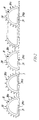
- The invention will be explained more fully by the following description of embodiments which are just given by way of example, with reference to the drawing, in which
- fig. 1 schematically shows a first embodiment of a system according to the invention,
- fig. 2 is an enlarged section along the line II-II in fig. 1, and
- fig. 3 schematically shows a second embodiment according to the invention.
- Fig. 1 schematically shows a drying system which is generally designated 1. The drying system substantially consists of a
drying chamber 2 with anendless travelling grate 3 running in the direction of the arrow around two rollers 4 and 5, of which the first roller 4 is driven by means of a motor (not shown), and the other roller 5 is idling. The drying system moreover comprises anextruder 6 with a mouthpiece 7 which protrudes through an inlet opening 8 in thedrying chamber 2 directly above the feed end of thetravelling grate 3. The opposite end of the drying chamber is formed with a discharge opening 9 which accommodates asluice 10, whose importance will be described below. - The
extruder 6, which comprises at least one conveyor worm 11, receives the sludge in a funnel 12, to which the sludge is conveyed from the sludge basin or tank by means of a pump and/or transport system (not shown), during which the sludge is optionally dehydrated to a solid content of between 15 and 40% in a manner known per se, which will therefore not be mentioned in greater detail here. The conveyor worm 11 is driven by amotor 13 via a transmission 14 and, in the shown embodiment, is provided with an axially extendingcavity 15 which accommodates anelectric heating member 16 which is connected to apower supply 17. - When the system is in operation, the wet sludge is conveyed from the funnel 12 forwardly through the extruder to the mouthpiece 7 by the rotating conveyor worm 11, the sludge being heated during this process to almost 100 °C by the
heating member 16. This heating in connection with the simultaneous mechanical stirring imparted to the sludge by the conveyor worm, entails that the sludge will be pliable and easy to transport and extrude, and that theextruded string 18 has exactly the same temperature over its entire cross-section when it leaves the mouthpiece 7. - Then the
string 18 slides via anoptional chute 19 down to thetravelling grate 3, which runs with a speed adapted to the extrusion rate, such that the string is continuously moved towards the opposite end of the conveyor belt. Theextruded string 18 is heated during this by means of a plurality ofelectric heating members 20 which, like theheating member 16, are connected to thepower supply 17. As shown,heating members 20 are provided both above and below theextruded string 18, and the heat released by the heating members is most intensive initially where the need for heat to evaporate the water content of the sludge is greatest. To avoid loss of heat to the surroundings, the drying chamber is exteriorly provided with aheat insulating jacket 21. - Electric heating members are used in this case for the heating of the sludge in both the extruder and the drying furnace, but this is just an example of course, since it is possible to use any suitable heating source instead, such as the flue gases from a combustion furnace or gas or oil burners. However, in all cases the thermal capacities must be adjusted such that the temperature of the sludge in the extruder is brought almost to the boil before the sludge leaves the mouthpiece, following which the water content in the extruded string immediately begins to boil violently over the entire cross-section of the string, and this state is maintained until the string has reached the other end of the drying furnace.
- Several remarkable advantages are obtained by means of the above-mentioned special combination of heating the sludge from the moment this is supplied to the extruder and until it leaves the travelling grate in a dried state. Thus, the sludge does not adhere to and/or bake on to the travelling grate, as might otherwise be expected, because the water and steam, which are rapidly expelled to the surface of the sludge because of the boiling, settle as a protective layer between the sludge surface and the grate. Another considerable advantage is that the sludge will not be burnt or scorched, since the strong boiling and evaporation forms a zone of saturated water steam which settles around the string of sludge and keeps all oxygen spaced from it. The strong boiling along the entire drying zone in the drying chamber also entails that the water and the steam, which are expelled to the surface of the string by the steam pressure in the sludge, form a finely branched network of pores and channels which remain in the finished product, which will therefore be light and porous with excellent properties both as fuel and compost.
- Having passed the drying zone, the now dry string leaves the travelling grate, and during this movement the string impinges on an
inclined abutment plate 22 which breakes the relatively fragile string intosuitable pieces 23. However, in some cases the string may already have been broken to a certain extent because of i.a. thermal stresses. Thebroken pieces 23 fall directly down into thesluice 10, which has amill 24 that rotates in the direction of the arrow in operation and thereby chrushes thepieces 23 additionally tobits 25 which fall through alower opening 26 in thesluice 10. Thesebits 25 of dried sludge can now be used as fuel in e.g. a combustion system or as compost, if the sludge is free of harmful components, such as heavy metals and poisonous substances. - Considerable amounts of steam are generated during drying, which are successively removed via a
vent pipe 27 with adamper 28 to regulate the steam pressure in the actual drying chamber. The steam contains a considerable amount of energy which can be turned to account via a heat exchanger in e.g. a district heating system. - The embodiment shown in fig. 1 is of a very simple and inexpensive structure, which, however, is nevertheless extremely efficient. The streams of energy generated because of the drying are not recycled in a closed circuit in the system shown, but are discharged from it and utilized in a greater system, which may e.g. be a district heating system which is supplied with heat from a municipal combustion system. The flue gases from this may be used as a heat energy source for the drying process, the flue gases still liberating heat and the generated steam from this for heating the water of the district heating system, and the dried sludge as fuel in the combustion system. An excellent operation economy at relatively modest initial costs is obtained by means of such a combination between the shown drying system and an already existing larger energy system.
- Fig. 2 is a cross-sectional view of a fragment of the travelling
grate 3 with a plurality ofextruded strings 18 which are disposed closely to each other. Each of these strings is tubular and has a base 29 by which the string rests on the grate, and anupper portion 30 which arches above the base in e.g. a cycloide shape, which ensures that the weight of the string can only apply compressive stresses to the at any rate initially very weak wall of the upper portion. As shown, theupper portion 30 is moreover provided with a plurality oflongitudinal ribs 30a, which serve to considerably increase the surface of the extruded string to promote evaporation. The arched shape of the upper portion moreover entails that the radiant heat from the heat sources in the drying chamber can reach substantially all portions of the outer surface of the string. In this case, the water can also advantageously evaporate from the inner surface of the string, since the generated steam can escape through alongitudinal gap 29a in thebase 29. - Of course, the shape of the string cross-section shown in fig. 2 is just an example, since the cross-section may have any other expedient shape within the scope of the invention. Thus, the cross-section may be four-sided, oval, round or star-shaped, just as it may optionally be solid or hollow and does not have to be provided with longitudinal ribs. However, under any circumstances, a large surface with respect to the area of the cross-section is desired.
- Fig. 3 schematically shows a second embodiment of the drying system, where parts corresponding to those shown in fig. 1 are provided with the same reference numerals. The actual drying system is substantially constructed in the same manner as described in connection with fig. 1 and operates in the same manner, but in this case the drying system is additionally provided with a heat recovery system, and the primary heat for the drying process is added by means of one or
more gas burners 31 which burn with aflame 32 in aseparate combustion chamber 33 spaced from the dryingchamber 2 by means of a partition 34, from which the heat from thegas flame 32 is transferred indirectly as radiant heat to the extrudedstring 18. - The flue gases from the combustion of the gas in the
combustion chamber 33 is drawn out of this and discharged to the atmosphere by means of aventilator 36 via avent pipe 35 in which across heat exchanger 37 is inserted. The necessary amount of air for the combustion process is likewise added through thiscross heat exchanger 37, but in counterflow to the hot flue gases so that the heat energy of these is utilized for heating the combustion air. As shown, this is introduced by means of ablower 39 and conveyed, as mentioned, through thecross heat exchanger 37 and further on from this via anair channel 40 into the dryingchamber 2. This chamber accommodates a plurality of baffle plates 41, which are so arranged that the hot combustion air is caused to pass up and down between the extruded sludge strings 18 before the air leaves the dryingchamber 2 via thevent pipe 27. The air absorbs and entrains the steam during this passage which is generated by the evaporation of the water content of the sludge, it being observed in this connection that because of the extremely rapid evaporation process there will still be a cushion of steam close to the surface of the sludge strings to keep the oxygen of the air spaced from the strings, so that these are not burnt or scorched. A contributory reason of this advantageous circumstance is that a network of pores and channels is formed already from the beginning of the evaporation process which rapidly convey water and steam to the surface also at the end of the evaporation process. As appears, the heat content in the preheated combustion air effectively contributes to heating the sludge strings and promoting the evaporation of the water content of these, while the air convection equalizes differences in temperature between surface portions which receive different amounts of radiant heat from the partition 34 because of their location. - Having passed the drying
chamber 2, the air may contain other gases in addition to water steam which are released by heating of the sludge strings. The air thus mixed is then conveyed via thevent pipe 27 to acondenser 42 in which the air is cooled down to a temperature of slightly below 100 °C, so that the water steam is condensed to generate a slight negative pressure in the dryingchamber 2 to ensure that poisonous or malodorous gases from the drying process do not escape through possible leaks in the drying chamber to the surroundings. - In the shown case, cooling of the air takes place by means of a water mist 43 which is ejected by an
atomizer nozzle 44, which is supplied with water under pressure via awater conduit 47 by apump 46, which sucks up the necessary water from asewage basin 45 by means of asuction line 48. The cooling water is then conveyed together with the condensed water steam by means of a pump back to thesewage basin 45 again via awater conduit 51, which accommodates a cross heat exchanger 50. An air flow from anair inlet 53 is moreover passed through the cross heat exchanger 50 by means of ablower 52 in co-current with the warm cooling and condensed water which thereby releases its heat content to the air, which, in heated state, is conveyed further on via anair channel 54 to a storage and dryingsilo 55, which receives the resulting dried sludge inbits 25 from thesluice 10 by means of aconveyor 56. The heat from the condensed water is hereby utilized for after-drying the sludge so that the end product will be very dry and suitable for use in particular as a fuel. - After the steam content of the air has condensed in the
condenser 42, the air is conveyed further on via anair channel 58 to acyclone drop separater 57 by means of ablower 59, which is inserted in anair channel 60 connected with the upper part of thecylone drop separater 57. Water drops which might have been entrained by the air flow from thecondenser 42, are now separated in thecyclone drop separater 57 and are conveyed via thewater conduit 51 and the cross heat exchanger 50 together with the cooling and condensed water to thesewage basin 45. In addition to the amount of sewage which is thus recirculated in the above-mentioned circuit, fresh sewage from the drying process will of course continuously be supplied to thesewage basin 45. However, it has been found that this sewage is so clean that it can readily be used for several different industrial purposes or for watering of fields. - As appears, the steam content of the air is thus removed in the
condenser 42 and water drops, if any, in thecyclone drop separater 57. However, the air may still have a content of hydrocarbons and other non-condensable gases. Since the air is finally fed to thegas burner 31 by means of theblower 59 as combustion air, these gases are incinerated because of their high temperatures which occur during the combustion. The air is then completely cleaned of hydrocarbons and malodorous gases and can readily be discharged to the atmosphere. If desired, a catalyst and optionally a soot separater may additionally be inserted in thevent pipe 35 to ensure that even the strictest threshold requirements are observed. - It is mentioned above how the sludge is preheated in the extruder, and the advantages involved hereby for the overall drying process have been explained. However, the essential feature is that the sludge is fed to the drying chamber with a relatively high temperature, and the sludge may therefore just as well be preheated before reaching the extruder, e.g. during transport to it. In this case the extruder is expediently insulated to keep the temperature of the preheated sludge at a desired level. For the preheating, it is then possible to use e.g. the flue gases which are discharged from the
cross heat exchanger 37, and which are preferably discharged with a temperature of above 100 °C to avoid deposits of corrosive condensates. In a particularly simple and advantageous embodiment of the invention in this connection, the hot flue gases are caused to bubble directly up through the sludge which will thereby advantageously serve as a regular after-filter for the flue gases. - A tubular drying chamber with a length of 3 m and a diameter of 0.6 m was used in a test. The upper half of the tubular wall formed a partition to a semicircular combustion chamber which has heated by means of a gas burner. A conveyor belt of almost the same length as the drying chamber and with a width of 0.5 m was placed in the centre of the drying chamber. A round sludge strings were evenly distributed over the width of the belt by means of an extruder which had a mouthpiece with 57 nozzles with a diameter of 6.5 mm. The flue gases from the combustion were discharged directly to the atmosphere from the combustion chamber end nearest to the extruder, while the generated water steam from the drying process was sucked out of the drying chamber to the atmosphere from the opposite end.
- The extruded amount of sludge was 0.8 kg per min., and the speed of the belt was adapted to the rate of 0.6 m per min. at which the sludge left the mouthpiece of the extruder, so that the complete drying time was about 5 min. The temperature in the drying chamber was 435 °C, and the discharge temperature of the flue gases from the combustion chamber was 550 °C. After drying, the sludge was removed from the drying chamber via a rotating gate in which the strings of sludge were broken down into small pill-shaped pieces which were found to have a dry matter content of 90%. This is sufficient if the dried sludge is to be used e.g. for composting, and if it is to be used as fuel, additional water can easily be removed to the necessary extent in a storage and drying silo.
- As appears, the test system have a capacity of 48 kg of wet sludge per hour with an evaporation capacity of 25.6 kg of water per cm² conveyor belt.
- During drying no form of volume shrinkage was observed, and the resulting dried product was found to have a light and porous structure and was in no way either charred or scorched in spite of the high temperature impact in the drying chamber. Because of the porous structure the dried sludge product could easily be converted biologically to compost, just as the product was found to be an excellent fuel.
- Although the method and the system of the invention have been described in the foregoing on the assumption that it was sewage sludge that was to be dried, the method and the system can be used equally well and with the same advantages for drying many other types of sludge which might occur in connection with e.g. industrial processes,
Claims (11)
- A method of completely or partially dehydrating sludge which originates from e.g. sewage, said sludge being transported on a travelling grate from an inlet to a discharge opening in a drying chamber with the addition of heat, characterized in that the sludge is fed to the drying chamber in one or more strings and that said addition of heat is so intense that the water in the sludge immediately begins to boil and a zone of preferably saturated water steam is formed at any rate in the immediate vicinity of the sludge.
- A method according to claim 1, characterized in that the sludge is fed to the drying chamber by means of an extruder.
- A method according to claim 1 or 2, characterized in that the sludge is preheated, preferably at a temperature of between 80 and 100°C.
- A method according to claim 1, 2 or 3, characterized in that the contents in a condenser connected with the drying chamber are cooled to a temperature of below 100°C.
- A method according to any of the claims 1-4, wherein heating takes place by means of the heat generated from a combustion process, characterized in that the combustion air for this process is first conveyed through the drying chamber with such a temperature that a zone of preferably saturated water steam is constantly left around the sludge.
- A method according to any of the claims 1-5, characterized in that in cross-section each string has a peripheral length which is at least three times as great as its smallest transverse dimension.
- A method according to any of the claims 1-6, characterized in that each string is provided with longitudinal ribs.
- A method according to any of the claims 2-7, characterized in that the transport means of the extruder are kept heated, or that the sludge is fed to the extruder in a preheated state.
- A system for performing the method stated in claims 1-8 and comprising a drying chamber with an inlet and a discharge opening arranged at their respective ends of said chamber, as well as an endless travelling grate arranged in the drying chamber for transporting the sludge to be dried from one opening to the other in the drying chamber with simultaneous addition of heat from one or more heat releasing means, characterized in that the system moreover comprises an extruder which has a mouthpiece relatively closely spaced above the feed end of the travelling grate, as well as one or more heat releasing means arranged around the extruder and/or in its transport means and adapted such that the sludge leaves the mouthpiece of the extruder in a preheated state.
- A system according to claim 9, characterized in that it comprises a steam condenser which is connected with the drying chamber and contains a cooling means for keeping the temperature in the condenser below 100°C.
- A system according to claim 9 or 10, characterized in that it comprises a gate with a rotatable mill arranged in the outlet opening of the drying chamber to divide the dried sludge strings into suitable smaller pieces and remove these from the drying chamber.
Applications Claiming Priority (3)
| Application Number | Priority Date | Filing Date | Title |
|---|---|---|---|
| DK156290A DK156290D0 (en) | 1990-06-28 | 1990-06-28 | METHOD AND PLANT FOR DRYING SLAM |
| DK1562/90 | 1990-06-28 | ||
| PCT/DK1991/000175 WO1992000250A1 (en) | 1990-06-28 | 1991-06-27 | A method and a system for drying sludge |
Publications (2)
| Publication Number | Publication Date |
|---|---|
| EP0536236A1 EP0536236A1 (en) | 1993-04-14 |
| EP0536236B1 true EP0536236B1 (en) | 1995-09-06 |
Family
ID=8106086
Family Applications (1)
| Application Number | Title | Priority Date | Filing Date |
|---|---|---|---|
| EP91912176A Expired - Lifetime EP0536236B1 (en) | 1990-06-28 | 1991-06-27 | A method and a system for drying sludge |
Country Status (11)
| Country | Link |
|---|---|
| US (1) | US5373647A (en) |
| EP (1) | EP0536236B1 (en) |
| AT (1) | ATE127434T1 (en) |
| AU (1) | AU8055791A (en) |
| CA (1) | CA2085583A1 (en) |
| DE (1) | DE69112831T2 (en) |
| DK (2) | DK156290D0 (en) |
| ES (1) | ES2078531T3 (en) |
| GR (1) | GR3018077T3 (en) |
| PL (1) | PL297364A1 (en) |
| WO (1) | WO1992000250A1 (en) |
Families Citing this family (37)
| Publication number | Priority date | Publication date | Assignee | Title |
|---|---|---|---|---|
| US5609769A (en) * | 1990-11-21 | 1997-03-11 | Jtj Systems, Inc. | Water treatment methods |
| DE4215933A1 (en) * | 1992-05-14 | 1993-11-18 | Enning Hans Juergen | Sludge drying |
| EP0559012A1 (en) * | 1992-03-05 | 1993-09-08 | Hans Jürgen Enning | Process and installation for drying digerted sludge |
| DE4218699C2 (en) * | 1992-06-09 | 2000-01-20 | Dornier Gmbh Lindauer | Flow dryer for drying sludge with filter arrangement |
| ATE177413T1 (en) * | 1994-07-04 | 1999-03-15 | Andreas Christian Wegier | PLANT FOR DRYING SLUDGE |
| BE1008170A3 (en) * | 1994-09-08 | 1996-02-06 | Um Engineering Sa | Sludge extruder |
| BE1008172A3 (en) * | 1995-01-12 | 1996-02-06 | Um Engineering Sa | Radiation chamber |
| US5634281A (en) * | 1995-05-15 | 1997-06-03 | Universal Drying Systems, Inc. | Multi pass, continuous drying apparatus |
| DE19526873C1 (en) * | 1995-07-22 | 1996-06-27 | Brochier Fa Hans | Extruder for sewage sludge |
| ES2156470B1 (en) | 1996-06-07 | 2002-01-16 | Gas Metropolitan & Co Lp | BLOWER FLUID DRYER AND GRANULATOR FOR THE TREATMENT OF RESIDUAL SUSPENSIONS. |
| US5740617A (en) * | 1997-04-23 | 1998-04-21 | Rittenhouse; Norman P. | Rotary drum dryer |
| DE19739864A1 (en) * | 1997-09-11 | 1999-03-18 | Dornier Gmbh Lindauer | Process for treating the exhaust air from thermal drying processes, in particular from processes during the drying of sewage sludge in sewage sludge dryers and plant for carrying out the process |
| FR2775064B1 (en) * | 1998-02-16 | 2000-05-05 | Sidel Sa | METHOD FOR DRYING HOLLOW BODIES AND DEVICE FOR CARRYING OUT SAID |
| ITVI980163A1 (en) * | 1998-09-07 | 2000-03-07 | Antonio Salviati | CONTINUOUS DRIER FOR MEATS, PASTA, POWDERS AND GRANULES. |
| US6539645B2 (en) | 2001-01-09 | 2003-04-01 | Mark Savarese | Drying apparatus and methods |
| AT412277B (en) | 2003-04-30 | 2004-12-27 | Armin Vonplon | METHOD AND DEVICE FOR CONTINUOUS DRYING OF GOOD, ESPECIALLY WASTE SLUDGE |
| CZ302688B6 (en) * | 2005-01-17 | 2011-08-31 | Ecoplant Praha Spol. S R. O. | Sludge incinerating process and apparatus for making the same |
| NZ541426A (en) | 2005-07-25 | 2008-06-30 | Flo Dry Engineering Ltd | Method and apparatus for drying |
| JP2007083122A (en) * | 2005-09-20 | 2007-04-05 | Central Res Inst Of Electric Power Ind | Method for dehydrating water-containing material using liquefied substance |
| KR100863476B1 (en) | 2008-01-09 | 2008-10-16 | 주식회사 대한테크 | Dryer |
| CN101671106B (en) * | 2009-09-28 | 2012-11-07 | 广州普得环保设备有限公司 | Method and device for sludge filter cake aerobic air drying |
| FR2954814B1 (en) * | 2009-12-30 | 2012-03-02 | Degremont | METHOD AND APPARATUS FOR DRYING PASTE MATERIALS, IN PARTICULAR SLUDGE OF PURIFICATION STATIONS, WITH GENERATION OF THERMAL ENERGY. |
| CN103383184A (en) * | 2012-11-23 | 2013-11-06 | 无锡众望四维科技有限公司 | Turning over and mixing structure for dryer |
| CN105783480A (en) * | 2014-12-18 | 2016-07-20 | 王浩 | Rapid drying and dewatering device for seed Chinese herbal medicines |
| JP6471598B2 (en) * | 2015-04-21 | 2019-02-20 | 宇部興産株式会社 | Method for estimating oxygen concentration in drying system in drying equipment |
| CN105546961A (en) * | 2015-12-26 | 2016-05-04 | 重庆市康泽科技开发有限责任公司 | Medicinal material stewing and drying device |
| CN109160710B (en) * | 2018-11-13 | 2021-09-21 | 榆林市中科环保科技发展有限公司 | Sludge treatment complete equipment with sludge pre-drying device and method thereof |
| US11788790B2 (en) * | 2019-02-21 | 2023-10-17 | North Carolina State University | Low energy drying of swine lagoon sludge or digestate |
| CN110260632A (en) * | 2019-06-10 | 2019-09-20 | 南京聚锋新材料有限公司 | Drying device is used in a kind of preparation of flame-resistant plastic-wood composite materials |
| CN110357383A (en) * | 2019-08-13 | 2019-10-22 | 上海华阜科技发展有限公司 | A kind of two phase flow urban sludge treatment device |
| JP7302031B2 (en) * | 2019-08-14 | 2023-07-03 | 安尼康(福建)環保設備有限公司 | Peristaltic propulsion drying equipment |
| CN110627341B (en) * | 2019-09-23 | 2022-01-28 | 广东省福日升绿色科技研究有限公司 | Sludge geothermal energy drying equipment capable of automatically controlling temperature difference |
| CN110715543A (en) * | 2019-11-26 | 2020-01-21 | 衡阳旭光锌锗科技有限公司 | Drying device |
| CN111253039B (en) * | 2020-02-28 | 2021-05-07 | 广东吉康环境系统科技有限公司 | Vehicle-mounted movable sludge treatment equipment |
| CN111908763A (en) * | 2020-08-13 | 2020-11-10 | 甘书学 | Movable sludge treatment equipment |
| CN113716831A (en) * | 2021-09-07 | 2021-11-30 | 广东华坤建设集团有限公司 | Sludge dewatering and fixing treatment system |
| CN114199648A (en) * | 2021-12-24 | 2022-03-18 | 沈阳环境科学研究院 | Pretreatment device for sludge detection sample |
Family Cites Families (11)
| Publication number | Priority date | Publication date | Assignee | Title |
|---|---|---|---|---|
| US2439384A (en) * | 1942-01-27 | 1948-04-13 | Union Starch & Refining Compan | Solid corn syrup manufacture |
| DE1080930B (en) * | 1958-10-08 | 1960-04-28 | Thea Pedersen Geb Engel | Mobile multi-belt dryer for grain or the like. |
| FR1583837A (en) * | 1968-04-30 | 1969-12-05 | ||
| FR2227230A1 (en) * | 1973-04-27 | 1974-11-22 | Mauviel Michel | Drying of sludge and town refuse - is effected by high frequency waves without incineration |
| US4244287A (en) * | 1979-07-09 | 1981-01-13 | Uop Inc. | Two-stage mechanical dewatering of sewage sludge |
| DE3531748A1 (en) * | 1985-09-05 | 1987-03-05 | Gfd Ges Fuer Dosiertechnik Mbh | Sewage sludge utilisation plant |
| US4756092A (en) * | 1986-09-10 | 1988-07-12 | Habersham Environmental Products | Method and apparatus for drying sludge |
| US4787323A (en) * | 1987-08-12 | 1988-11-29 | Atlantic Richfield Company | Treating sludges and soil materials contaminated with hydrocarbons |
| NL8801037A (en) * | 1988-04-21 | 1989-11-16 | Pannevis Bv | METHOD AND APPARATUS FOR REMOVING LIQUID FROM A MIXTURE OF SOLID AND LIQUID. |
| ES2042869T3 (en) * | 1988-05-24 | 1993-12-16 | Siemens Ag | PROCEDURE AND DEVICE FOR THE DRYING OF ACTIVATED SLUDGE. |
| EP0386274B1 (en) * | 1989-03-02 | 1995-03-08 | AXBRIDGE HOLDINGS Ltd. | Process and device for drying sewage sludge |
-
1990
- 1990-06-28 DK DK156290A patent/DK156290D0/en active Protection Beyond IP Right Term
-
1991
- 1991-06-27 AU AU80557/91A patent/AU8055791A/en not_active Abandoned
- 1991-06-27 CA CA002085583A patent/CA2085583A1/en not_active Abandoned
- 1991-06-27 ES ES91912176T patent/ES2078531T3/en not_active Expired - Lifetime
- 1991-06-27 AT AT91912176T patent/ATE127434T1/en not_active IP Right Cessation
- 1991-06-27 DE DE69112831T patent/DE69112831T2/en not_active Expired - Fee Related
- 1991-06-27 PL PL29736491A patent/PL297364A1/xx unknown
- 1991-06-27 EP EP91912176A patent/EP0536236B1/en not_active Expired - Lifetime
- 1991-06-27 US US07/958,354 patent/US5373647A/en not_active Expired - Fee Related
- 1991-06-27 DK DK91912176.4T patent/DK0536236T3/en active
- 1991-06-27 WO PCT/DK1991/000175 patent/WO1992000250A1/en active IP Right Grant
-
1995
- 1995-11-15 GR GR950403195T patent/GR3018077T3/en unknown
Also Published As
| Publication number | Publication date |
|---|---|
| WO1992000250A1 (en) | 1992-01-09 |
| EP0536236A1 (en) | 1993-04-14 |
| GR3018077T3 (en) | 1996-02-29 |
| ATE127434T1 (en) | 1995-09-15 |
| DK0536236T3 (en) | 1996-01-22 |
| PL297364A1 (en) | 1992-07-13 |
| DK156290D0 (en) | 1990-06-28 |
| ES2078531T3 (en) | 1995-12-16 |
| US5373647A (en) | 1994-12-20 |
| AU8055791A (en) | 1992-01-23 |
| DE69112831D1 (en) | 1995-10-12 |
| CA2085583A1 (en) | 1991-12-29 |
| DE69112831T2 (en) | 1996-02-08 |
Similar Documents
| Publication | Publication Date | Title |
|---|---|---|
| EP0536236B1 (en) | A method and a system for drying sludge | |
| JP2657503B2 (en) | Waste treatment and rotary kiln therefor | |
| US5809664A (en) | Spout-fluid bed dryer and granulator for the treatment of animal manure | |
| US6101739A (en) | Method and apparatus for treating exhaust gases of thermal drying processes and particularly processes for drying sewage sludge | |
| US4872954A (en) | Apparatus for the treatment of waste | |
| US6532880B2 (en) | Method and apparatus for drying and incineration of sewage sludge | |
| US3771468A (en) | Waste disposal | |
| JPS6338240B2 (en) | ||
| JP4445147B2 (en) | Sludge treatment method and apparatus | |
| KR20010078756A (en) | Multifunctional disposal apparatus | |
| US4248164A (en) | Sludge drying system with sand recycle | |
| US3772998A (en) | Method of and apparatus for the combustion of sludge | |
| JPH02237700A (en) | Sludge drying method | |
| WO1990009967A1 (en) | A device for the dehydration of sewage sludge | |
| US4153411A (en) | Rotary sludge drying system with sand recycle | |
| JP4445148B2 (en) | Sludge treatment method and apparatus | |
| HU218755B (en) | Method and device for processing waste with a calorific value | |
| JPH05500529A (en) | Methods and apparatus for purifying or treating substances | |
| KR100520347B1 (en) | Energy saving type sludge carbonization equipment using regenerative heat exchanger | |
| KR100933437B1 (en) | High water content of smokeless device | |
| RU2038344C1 (en) | Dung processing device | |
| CN110396417A (en) | A kind of desiccation charing process system and treatment process | |
| DE10224173A1 (en) | Method for combined draining and drying of sludges, with subsequent sterilization by hot drying gases, involves replacement of a percentage of these gases with a hot combustion gas | |
| WO1997047933A1 (en) | A spout-fluid bed dryer and granulator for the treatment of waste slurries | |
| RU2798552C1 (en) | Complex for thermal neutralization and utilization of organic waste |
Legal Events
| Date | Code | Title | Description |
|---|---|---|---|
| PUAI | Public reference made under article 153(3) epc to a published international application that has entered the european phase |
Free format text: ORIGINAL CODE: 0009012 |
|
| 17P | Request for examination filed |
Effective date: 19921215 |
|
| AK | Designated contracting states |
Kind code of ref document: A1 Designated state(s): AT BE CH DE DK ES FR GB GR IT LI LU NL SE |
|
| 17Q | First examination report despatched |
Effective date: 19931217 |
|
| GRAA | (expected) grant |
Free format text: ORIGINAL CODE: 0009210 |
|
| RAP1 | Party data changed (applicant data changed or rights of an application transferred) |
Owner name: FLS INDUSTRIES A/S |
|
| ITF | It: translation for a ep patent filed |
Owner name: PROROGA CONCESSA IN DATA: 27.10.95;BARZANO' E ZANA |
|
| AK | Designated contracting states |
Kind code of ref document: B1 Designated state(s): AT BE CH DE DK ES FR GB GR IT LI LU NL SE |
|
| REF | Corresponds to: |
Ref document number: 127434 Country of ref document: AT Date of ref document: 19950915 Kind code of ref document: T |
|
| REF | Corresponds to: |
Ref document number: 69112831 Country of ref document: DE Date of ref document: 19951012 |
|
| ET | Fr: translation filed | ||
| REG | Reference to a national code |
Ref country code: ES Ref legal event code: FG2A Ref document number: 2078531 Country of ref document: ES Kind code of ref document: T3 |
|
| REG | Reference to a national code |
Ref country code: DK Ref legal event code: T3 |
|
| REG | Reference to a national code |
Ref country code: GR Ref legal event code: FG4A Free format text: 3018077 |
|
| PGFP | Annual fee paid to national office [announced via postgrant information from national office to epo] |
Ref country code: GB Payment date: 19960520 Year of fee payment: 6 |
|
| PGFP | Annual fee paid to national office [announced via postgrant information from national office to epo] |
Ref country code: SE Payment date: 19960524 Year of fee payment: 6 |
|
| PGFP | Annual fee paid to national office [announced via postgrant information from national office to epo] |
Ref country code: GR Payment date: 19960530 Year of fee payment: 6 |
|
| PGFP | Annual fee paid to national office [announced via postgrant information from national office to epo] |
Ref country code: FR Payment date: 19960604 Year of fee payment: 6 |
|
| PGFP | Annual fee paid to national office [announced via postgrant information from national office to epo] |
Ref country code: BE Payment date: 19960612 Year of fee payment: 6 Ref country code: AT Payment date: 19960612 Year of fee payment: 6 |
|
| PGFP | Annual fee paid to national office [announced via postgrant information from national office to epo] |
Ref country code: DK Payment date: 19960613 Year of fee payment: 6 |
|
| PGFP | Annual fee paid to national office [announced via postgrant information from national office to epo] |
Ref country code: NL Payment date: 19960618 Year of fee payment: 6 Ref country code: ES Payment date: 19960618 Year of fee payment: 6 |
|
| PGFP | Annual fee paid to national office [announced via postgrant information from national office to epo] |
Ref country code: LU Payment date: 19960701 Year of fee payment: 6 |
|
| PLBE | No opposition filed within time limit |
Free format text: ORIGINAL CODE: 0009261 |
|
| STAA | Information on the status of an ep patent application or granted ep patent |
Free format text: STATUS: NO OPPOSITION FILED WITHIN TIME LIMIT |
|
| PGFP | Annual fee paid to national office [announced via postgrant information from national office to epo] |
Ref country code: DE Payment date: 19960718 Year of fee payment: 6 Ref country code: CH Payment date: 19960718 Year of fee payment: 6 |
|
| 26N | No opposition filed | ||
| PG25 | Lapsed in a contracting state [announced via postgrant information from national office to epo] |
Ref country code: LU Free format text: LAPSE BECAUSE OF NON-PAYMENT OF DUE FEES Effective date: 19970627 Ref country code: GB Free format text: LAPSE BECAUSE OF NON-PAYMENT OF DUE FEES Effective date: 19970627 Ref country code: DK Free format text: LAPSE BECAUSE OF NON-PAYMENT OF DUE FEES Effective date: 19970627 Ref country code: AT Effective date: 19970627 |
|
| REG | Reference to a national code |
Ref country code: DK Ref legal event code: EBP |
|
| PG25 | Lapsed in a contracting state [announced via postgrant information from national office to epo] |
Ref country code: SE Effective date: 19970628 Ref country code: ES Free format text: LAPSE BECAUSE OF EXPIRATION OF PROTECTION Effective date: 19970628 |
|
| PG25 | Lapsed in a contracting state [announced via postgrant information from national office to epo] |
Ref country code: LI Free format text: LAPSE BECAUSE OF NON-PAYMENT OF DUE FEES Effective date: 19970630 Ref country code: GR Free format text: LAPSE BECAUSE OF NON-PAYMENT OF DUE FEES Effective date: 19970630 Ref country code: CH Free format text: LAPSE BECAUSE OF NON-PAYMENT OF DUE FEES Effective date: 19970630 Ref country code: BE Effective date: 19970630 |
|
| BERE | Be: lapsed |
Owner name: FLS INDUSTRIES A/S Effective date: 19970630 |
|
| PG25 | Lapsed in a contracting state [announced via postgrant information from national office to epo] |
Ref country code: NL Effective date: 19980101 |
|
| REG | Reference to a national code |
Ref country code: CH Ref legal event code: PL |
|
| GBPC | Gb: european patent ceased through non-payment of renewal fee |
Effective date: 19970627 |
|
| PG25 | Lapsed in a contracting state [announced via postgrant information from national office to epo] |
Ref country code: FR Free format text: LAPSE BECAUSE OF NON-PAYMENT OF DUE FEES Effective date: 19980227 |
|
| EUG | Se: european patent has lapsed |
Ref document number: 91912176.4 |
|
| NLV4 | Nl: lapsed or anulled due to non-payment of the annual fee |
Effective date: 19980101 |
|
| PG25 | Lapsed in a contracting state [announced via postgrant information from national office to epo] |
Ref country code: DE Free format text: LAPSE BECAUSE OF NON-PAYMENT OF DUE FEES Effective date: 19980303 |
|
| REG | Reference to a national code |
Ref country code: FR Ref legal event code: ST |
|
| REG | Reference to a national code |
Ref country code: FR Ref legal event code: ST |
|
| REG | Reference to a national code |
Ref country code: ES Ref legal event code: FD2A Effective date: 20000601 |
|
| PG25 | Lapsed in a contracting state [announced via postgrant information from national office to epo] |
Ref country code: IT Free format text: LAPSE BECAUSE OF NON-PAYMENT OF DUE FEES;WARNING: LAPSES OF ITALIAN PATENTS WITH EFFECTIVE DATE BEFORE 2007 MAY HAVE OCCURRED AT ANY TIME BEFORE 2007. THE CORRECT EFFECTIVE DATE MAY BE DIFFERENT FROM THE ONE RECORDED. Effective date: 20050627 |