EP0536093B1 - Maschine zur automatischen und kontinuierlichen Herstellung von Drahtspulen - Google Patents
Maschine zur automatischen und kontinuierlichen Herstellung von Drahtspulen Download PDFInfo
- Publication number
- EP0536093B1 EP0536093B1 EP92830521A EP92830521A EP0536093B1 EP 0536093 B1 EP0536093 B1 EP 0536093B1 EP 92830521 A EP92830521 A EP 92830521A EP 92830521 A EP92830521 A EP 92830521A EP 0536093 B1 EP0536093 B1 EP 0536093B1
- Authority
- EP
- European Patent Office
- Prior art keywords
- tools
- pneumatic cylinder
- rods
- fixed
- plate
- Prior art date
- Legal status (The legal status is an assumption and is not a legal conclusion. Google has not performed a legal analysis and makes no representation as to the accuracy of the status listed.)
- Expired - Lifetime
Links
Images



Classifications
-
- B—PERFORMING OPERATIONS; TRANSPORTING
- B65—CONVEYING; PACKING; STORING; HANDLING THIN OR FILAMENTARY MATERIAL
- B65H—HANDLING THIN OR FILAMENTARY MATERIAL, e.g. SHEETS, WEBS, CABLES
- B65H75/00—Storing webs, tapes, or filamentary material, e.g. on reels
- B65H75/50—Methods of making reels, bobbins, cop tubes, or the like by working an unspecified material, or several materials
-
- B—PERFORMING OPERATIONS; TRANSPORTING
- B65—CONVEYING; PACKING; STORING; HANDLING THIN OR FILAMENTARY MATERIAL
- B65H—HANDLING THIN OR FILAMENTARY MATERIAL, e.g. SHEETS, WEBS, CABLES
- B65H75/00—Storing webs, tapes, or filamentary material, e.g. on reels
- B65H75/02—Cores, formers, supports, or holders for coiled, wound, or folded material, e.g. reels, spindles, bobbins, cop tubes, cans, mandrels or chucks
- B65H75/18—Constructional details
- B65H75/20—Skeleton construction, e.g. formed of wire
-
- Y—GENERAL TAGGING OF NEW TECHNOLOGICAL DEVELOPMENTS; GENERAL TAGGING OF CROSS-SECTIONAL TECHNOLOGIES SPANNING OVER SEVERAL SECTIONS OF THE IPC; TECHNICAL SUBJECTS COVERED BY FORMER USPC CROSS-REFERENCE ART COLLECTIONS [XRACs] AND DIGESTS
- Y10—TECHNICAL SUBJECTS COVERED BY FORMER USPC
- Y10T—TECHNICAL SUBJECTS COVERED BY FORMER US CLASSIFICATION
- Y10T29/00—Metal working
- Y10T29/49—Method of mechanical manufacture
- Y10T29/49616—Structural member making
Definitions
- This design patent application concerns a machine for the automatic and continuous production of wire winding spools, in particular welding wire for welding machines.
- the frame of these metal spools consists of a core and two side annular flanges which hold the wire wound around the core.
- the latter is generally a cylindrical cage having a horizontal axis whose bars coincide with the middle transverse section of a series of radial "U” shaped brackets whose vertical, opposing and parallel arms are welded to two rings which form, together with said arms, the two side flanges of the spool.
- the machine according to the invention is an absolute novelty with respect to past techniques in that currently the production procedure used for manufacturing spools involves the preparation of "U" shaped brackets from a metal rod which is repeatedly cut to size and bent by a press, as well as the preparation of rings, again from metal rod, which is repeatedly cut to size and welded, after being bent into a ring by means of shaping tools.
- the automatic machine according to the invention can, on the other hand, continuously produce metal spools from two straight metal rods which are fed horizontally and parallel to each other, in intermittent steps, through three successive operating stations.
- the first station consists of:
- the second station consists of:
- the third station consists of:
- each step is equal to the distance between one bracket and another, measured along the perimeter of the polygonal rings of the spool.
- the pair of parallel straight metal rods is moved forward by a step exactly equal to one eighth of the perimeter of the regular polygon that the two rods form after having being bent repeatedly in the second station.
- each polygonal ring is double the number of brackets of the spool since in standard spools the brackets are welded, as an alternative, at the centre of the sides of the two polygonal rings.
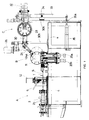
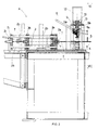
- the first station (A) consists of tools for grasping and pulling the two rods (T), which are adjacent and parallel on the same horizontal plane, in intermittent steps.
- These tools consist of a clip for each rod, consisting of two superimposed rollers (1) which are held by means of a pneumatic actuator (1a), against each other, so as to clasp the rod "T" lying between the same.
- the two clips are installed on the two sides of a supporting plate (2a), which is part of a trolley which performs alternating horizontal runs by means of a pneumatic cylinder (3), whose shaft is fixed on the back of the supporting plate (2a).
- cylinder (3) is installed inside two upright columns (3a and 3b) which are fixed to base (4) of the machine.
- Upright columns (3a and 3b) feature through holes into which the two horizontal bars (2b), which connect the front plate (2a) and the back plate (2c) of the trolley, are housed and slide.
- the first station (A) consists of tools for lifting the metal brackets (S) placed over one grouping slide (5), one at a time.
- the first station (A) also has tools for positioning and welding bracket (S), which is lifted from the slide (5), on the rods (T).
- the first bracket (S), of the row of brackets moving along the slide (5), is pushed by the back row, so that it abuts against a transfer track (6a), on a vertical and orthogonal plane in the direction in which the pairs of rods (T) are moving.
- Said track (6a) is cut into the rear face of a plate (6) screwed on the wall of a vertical plate (7) projecting from the base (4) of the machine.
- the track (6a) has a cutter (8) which is driven in alternating horizontal runs by a pneumatic cylinder (9) which is supported by a frame (10) fixed on the top edge and on the bottom edge of the above plate (6).
- a clamp (10) consisting of a fixed vertical plate (10a) and a mobile counter-plate (10b), driven by a pneumatic cylinder (11) between which the cutter (8) drives the bracket (S) lifted from track (5).
- Clamp (10) is fixed to the base of the shaft (12a) of a pneumatic cylinder (12), having a vertical axis, installed above a platform (13) supported by legs (13a) fixed to the base (4) of the machine.
- bracket (S) When a bracket (S) enters the clamp (10), the mobile plate (10b) fixes it against the fixed plate (10a) and the clamp (10) is then lowered by the cylinder (12) so as to take the "legs" of the bracket (S) into direct contact with the two underlying rods (T), resting above two grooved blocks (14).
- the bracket (S) is fixed to the rods (T) by means of an electrical welding machine, so that for a moment current is passed to the clamp (10) and to the blocks (14) by means of the respective electric wires (15 and 16).
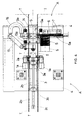
- the second station (B) consists of tools for simultaneously bending the two "T" rods ; with particular reference to fig. 3A, it can be noted that each rod (T) is bent by a vertically translating punch (17a) which cooperates with two overlying fixed supporting bases (18a and 19a) against which the rod (T) is pushed from bottom to top, by the punch (17a) by means of a hydraulic cylinder (20a) having a vertical axis.
- the punch (17a) obviously intervenes rhythmically in synchronism with the intermittent forward movement of the pair of rods (T).
- the supporting bases are supported by respective horizontal sliding blocks which slide transversely with respect to the forward movement of the two rods (T).
- Punch (17b) driven by its own pneumatic cylinder (20b) cooperates with two fixed overlying supporting bases (18b and 19b) having an identical and symmetrical profile to that of the supporting bases (18a and 18b).
- the supporting bases (18a and 19a) are pushed back by a hydraulic cylinder having a horizontal axis (21a), while the supporting bases (18b and 19b) - which had previously been idle and pushed back - are now moved forward by means of a hydraulic cylinder having a horizontal axis (21b).
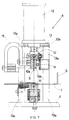
- the spool (R) is carried from the second station (B) to the third station (C) by means of a pair of adjacent oscillating arms (24) terminating with a clip (24a) whose jaws are opened and closed pneumatically.
- the arms (24) are mounted on a horizontal shaft (25) which are rotated in alternation by a geared motor (26) by the intervention of a driving belt (27).
- the oscillating arms (24) carry the spool (R), from station (B), into two circular opposing plates (28), supported externally by plates (29a) being part of a trolley, consisting of two plates (29a and 29b) connected by two circular bars (29c) which are housed and slide in guide bushings (30a) on the support (30) of a bearing portal frame whose uprights (30b) are fixed and rest on the base (4) of the machine.
- Plate (29a) is fixed to the shaft (31a) of a pneumatic cylinder (31) having a horizontal axis, installed on the external wall of said support (30), whereby the plates (28) can, at the appropriate time, be drawn closer to stop the spool (R) fitted between the same and supported by the oscillating arms (24).
- the internal surfaces of the plates (28) have an annular groove (28a) and a series of radial grooves (28b) where the peripheral rings of the spool (R) and the side "legs" of the bracket (S), can be housed respectively.
- Said plates also have two diametrically opposing slots, one (28c) for housing the clips (24a) of the oscillating arms (24) and the other (28b) for housing the tips (32a) of the welding pincers (32).
- the head welding pincers (32) are installed in staggered position, on an upright (33) having at the middle of its side two coaxial and opposing horizontal pins (34) which rotate and slide within respective support housings (34a).
- the oscillation of the column (33) is by means of a pneumatic cylinder (35), whose shaft (35a) is hooked to the base of the column (33) while the translation of the column (33) is obtained by means of a hydraulic cylinder (36).
- the oscillation of the column (33) makes it possible to insert the tips (32a) of the welding pincers (32) into the slots (28d) of the plates (28) when the peripheral rings of the spool (R) are welded; once the first of the two rings has been welded, the welding pincers (32) are first pushed backwards, thanks to the oscillation of the column (33) and then carried in front of the next ring which is to be welded, thanks to the translation of the column (33) by means of the cylinder (36).
- the pincer (32) is once again pushed back, while the plates (28) are drawn away so that the finished spool (R) falls into the collection and unloading tray.
Landscapes
- Wire Processing (AREA)
- Winding, Rewinding, Material Storage Devices (AREA)
Claims (2)
- Maschine zur automatischen Endlosherstellung von Spulen zur Aufwicklung von Metalldraht, bestehend aus drei hintereinandergeschalteten Arbeitsstationen, dadurch gekennzeichnet daß die erste Arbeitsstation (A) folgendes umfaßt:- Vorrichtungen zum Greifen und intermittierenden Einzug der nebeneinanderliegenden Rundeisenpaaren (T), bestehend aus einem Paar Zangen, gebildet aus zwei übereinanderliegenden Rollen (1), die sich mittels eines Pneumatiktriebes (1a) schließen und auf den beiden Seiten einer Trägerplatte (2a) montiert werden, die Teil eines Schlittens ist, der von einem Pneumatikzylinder (3) horizontal hin- und hergezogen wird, dessen Schaft auf der Rückseite der besagten Platte (2a) befestigt ist; wobei vorgesehen ist, daß der besagte Zylinder (3) im Innern von zwei am Maschinengehäuse (4) befestigten Steigrohren (3a und 3b) installiert und mit durchgehenden Bohrungen versehen ist, in denen die beiden horizontalen Stangen (2b) geführt werden, die die vordere Platte (2a) und die rückwärtige Platte (2c) des besagten Schlittens miteinander verbinden;- Vorrichtungen zur Einzelentnahme der Metallbügel (S), die in Form eines Reiters auf einer Stapelrutsche (5) aufgesteckt sind, bestehend aus einer mittels Pneumatikzylinder (9) betätigten Fallvorrichtung mit Horizontalvorschub (8) und gleitend auf einer Führungspiste (6a) auf der Innenseite einer Platte (6), die an der Wand einer dasGehäuse (4) der Maschinen überragenden Vertikalplatte (7) angeschraubt ist;- Vorrichtungen zum Positionieren und Schweißen des aus der Stapelrutsche (5) entnommenen Bügels (S) über den Rundeisen (T), bestehend aus einer Klemme (10), die sich vor dem Ausgang der Piste (6a) befindet und aus einem festen Vertikalteller(10a) sowie einem beweglichen Konterteller (10b) gebildet wird und von einem Pneumatikzylinder (11) betätigt wird; wobei vorgesehen ist, daß die besagte Klemme (10) auf der Basis des Schaftes (12a) eines Pneumatikzylinders (12) mit Vertikalachse befestigt ist, der über einer Plattform (13) installiert ist, die mit Beinen (13a) versehen ist, welche am Gehäuse (4) der Maschine befestigt sind; des weiteren sind Kabel (15 und 16) zur Elektroversorgung der Klemme (10) und der Sperren (14) vorgesehen ;die zweite Arbeitsstation (B) folgendes umfaßt:- Vorrichtungen zum gleichzeitigen Biegen der beiden Rundeisen (T), bestehend aus einer Stanze (17a), die von einem Pneumatikzylinder (20a) in vertikaler Richtung bewegt wird und zusammen mit zwei darüberliegenden Anschlagsockeln (18a und 19a) funktioniert, die von einem Horizontalschlitten gehalten werden, der von einem Pneumatikzylinder (21a) betätigt wird; wobei vorgesehen ist, daß die letzte Biegung der Rundeisen durch eine andere Stanze (17b) vorgenommen wird, die die Stanze (17a) unterstützt und dieser gegenüberliegt und dasselbe, in Symmetrie zur Stanze (17a) angelegte Profil besitzt; ebenso ist vorgesehen, daß die Stanze (17b) durch einen eigenen Pneumatikzylinder (20b) mit Vertikalachse betätigt wird und zusammen mit zwei darüberliegenden Anschlagsockeln (18b und 19b) funktioniert, die dasselbe , in Symmetrie zu dem der Sockel (18a und 19a) angelegte Profil besitzen und von einem Pneumatikzylinder (21b) betätigt werden;- Vorrichtungen zum Schneiden der Rundeisen (T), bestehend aus einem Messer (22a), das auf der Stanze (17b) befestigt ist und zusammen mit einem Kontermesser (22) funktioniert, das von einer Pneumatikvorrichtung (23) betätigt wird;die dritte Arbeitsstation (C) folgendes umfaßt:- Vorrichtungen zum Entnehmen der Spule (R) aus der zweiten Arbeitsstation und Transportieren derselben zur dritten Arbeitsstation, bestehend aus zwei nebeneinanderliegenden Schwingarmen (24), die in einer Greifzange (24a) enden, deren Backen sich pneumatisch öffnen und schließen und welche auf einer Horizontalwelle (25) installiert sind, die von einem Getriebemotor (26) durch Zwischenschalten eines Übertragungsriemens (27) in Wechseldrehungen gebracht wird;- Vorrichtungen zum Arretieren der Spule (R) während des Schweißens, bestehend aus zwei gegenüberliegenden Drehtellern (28), die äußerlich durch Platten (29a) gehalten werden, die zu einem Gestell gehören, das aus zwei Platten (29a und 29b) besteht, die durch zwei Rundstangen (29c) verbunden sind, die in Führungsbuchsen (30a) beweglich gelagert sind, die auf dem Sturz (30) eines tragenden Portalgestells, dessen Pfosten (30b) auf dem Gehäuse (4) der Maschine aufliegen und befestigt sind; wobei vorgesehen ist, daß die besagte Platte (29a) auf dem Schaft (31a) eines Pneumatikzylinders (31) mit horizontaler Achse befestigt ist, der auf der Außenwand des besagtens Sturzes (30) installiert ist; wobei des weiteren vorgesehen ist, daß die besagten Teller (28) auf ihrer Innenseite eine ringförmige Rille (28a) und eine Reihe von radial angeordneten Rillen (28b) aufweisen, während sie auf ihrer Außenseite zwei diametral gegenüberliegende Einschnitte besitzen, wobei einer davon (28c) zur Aufnahme der Zangen (24a) der Schwenkarme (24) und der andere (28d) zur Aufnahme der Spitzen (32a) der Schweißzange (32) dient;- Vorrichtungen zum Schweißen der Spule (R), die zwischen den Tellern (28) eingespannt ist, bestehend aus einer Stumpfschweißzange (32), die freitragend auf einem Steigrohr (33) installiert ist, das seitlich in der Mittellinie zwei koaxiale, gegenüberliegende, horizontale Stifte (34) besitzt, die drehbar und beweglich in den jeweiligen Sitzen (34a) gelagert sind; wobei zwei Pneumatikzylinder (35 und 36) zum Schwingen und Bewegen des Steigrohres (33) vorgesehen sind.
- Maschine zur automatischen Endlosherstellung von Spulen zur Aufwicklung von Metalldraht gemäß des obigen Anspruches, dadurch gekennzeichnet, daß ein intermittierender Vorschub der nebeneinanderliegenden Rundeisenpaare mittels der drei besagten, aufeinanderfolgenden Arbeitsstationen erfolgt, wobei der Vorschub dem Abstand zwischen den Bügeln entspricht, gemessen entlang des Umfangs der polygonalen Ringe der Spule.
Applications Claiming Priority (2)
| Application Number | Priority Date | Filing Date | Title |
|---|---|---|---|
| ITAN910035 | 1991-10-04 | ||
| ITAN910035A IT1253547B (it) | 1991-10-04 | 1991-10-04 | Macchina per la fabbricazione in automatico ed in continuo di rocchetti per l'avvolgimento di fili. |
Publications (2)
| Publication Number | Publication Date |
|---|---|
| EP0536093A1 EP0536093A1 (de) | 1993-04-07 |
| EP0536093B1 true EP0536093B1 (de) | 1995-12-20 |
Family
ID=11333546
Family Applications (1)
| Application Number | Title | Priority Date | Filing Date |
|---|---|---|---|
| EP92830521A Expired - Lifetime EP0536093B1 (de) | 1991-10-04 | 1992-09-23 | Maschine zur automatischen und kontinuierlichen Herstellung von Drahtspulen |
Country Status (5)
| Country | Link |
|---|---|
| US (1) | US5228613A (de) |
| EP (1) | EP0536093B1 (de) |
| DE (1) | DE69206942T2 (de) |
| ES (1) | ES2084330T3 (de) |
| IT (1) | IT1253547B (de) |
Families Citing this family (2)
| Publication number | Priority date | Publication date | Assignee | Title |
|---|---|---|---|---|
| US20070175877A1 (en) * | 2006-02-01 | 2007-08-02 | Lincoln Global, Inc. | Weld wire with large cast, method of making same, and loaded spool article of manufacture |
| CN113199179B (zh) * | 2021-04-30 | 2024-09-06 | 苏州瀚川智能科技股份有限公司 | Ic带全自动焊接装置 |
Family Cites Families (5)
| Publication number | Priority date | Publication date | Assignee | Title |
|---|---|---|---|---|
| US2957070A (en) * | 1957-03-26 | 1960-10-18 | Voigt & Haeffner Ag | Welding |
| CH536423A (de) * | 1971-02-18 | 1973-04-30 | Imex Ag | Verfahren und Vorrichtung zur Herstellung einer Bewehrung für Betondecken, Betonwände und dergleichen |
| FR2269387A1 (en) * | 1974-04-30 | 1975-11-28 | Herlin Bernard | Machine for mfg concrete reinforcement cages - uses bars bent about longitudinal bars and welded |
| AT365486B (de) * | 1979-08-03 | 1982-01-25 | Evg Entwicklung Verwert Ges | Maschine zum selbsttaetigen herstellen von geschweissten gittertraegern |
| IT1242416B (it) * | 1990-07-27 | 1994-03-04 | Compagnucci Spa | Procedimento per la fabbricazione in automatico ed in continuo di rocchetti di avvolgimento in tondino metallico. |
-
1991
- 1991-10-04 IT ITAN910035A patent/IT1253547B/it active IP Right Grant
-
1992
- 1992-09-22 US US07/949,800 patent/US5228613A/en not_active Expired - Fee Related
- 1992-09-23 DE DE69206942T patent/DE69206942T2/de not_active Expired - Fee Related
- 1992-09-23 ES ES92830521T patent/ES2084330T3/es not_active Expired - Lifetime
- 1992-09-23 EP EP92830521A patent/EP0536093B1/de not_active Expired - Lifetime
Also Published As
| Publication number | Publication date |
|---|---|
| DE69206942T2 (de) | 1996-08-14 |
| EP0536093A1 (de) | 1993-04-07 |
| ITAN910035A0 (it) | 1991-10-04 |
| IT1253547B (it) | 1995-08-08 |
| ES2084330T3 (es) | 1996-05-01 |
| US5228613A (en) | 1993-07-20 |
| ITAN910035A1 (it) | 1993-04-04 |
| DE69206942D1 (de) | 1996-02-01 |
Similar Documents
| Publication | Publication Date | Title |
|---|---|---|
| US5370324A (en) | Stator winding method and apparatus | |
| US6810581B2 (en) | Crimping apparatus for sub-harness production employing movable connector tables securable to frame members | |
| CN112332616A (zh) | 一种电机定子绕嵌扩一体机 | |
| CN112072873A (zh) | 转子排线绕线机 | |
| CN210041596U (zh) | 电机定子的绕线装置 | |
| CN110112871A (zh) | 电机定子的自动化生产线 | |
| CN111804846A (zh) | 一种电光花铁丝全自动快速下料夹紧设备 | |
| CN114520574A (zh) | 一种双轴飞叉马达绕线机 | |
| CN213585510U (zh) | 一种电机定子绕嵌扩一体机 | |
| KR20030058786A (ko) | 전동기 전기자용 절연코어 급지장치 | |
| EP0536093B1 (de) | Maschine zur automatischen und kontinuierlichen Herstellung von Drahtspulen | |
| KR100535216B1 (ko) | 전동기 전기자용 절연시트 급지장치 | |
| CN118942883A (zh) | 一种变压器用包铜箔焊飞线包胶组装机构 | |
| US4217937A (en) | Coil winding machine | |
| JP3571399B2 (ja) | フィルタの製造方法及びその製造装置 | |
| CN115632292B (zh) | 软母线预制成套设备 | |
| CN115782210B (zh) | 一种卷管穿管一体化装置及其使用方法 | |
| CN111243857A (zh) | 一种电感线圈及其绕线方法和绕线机 | |
| CN111243856A (zh) | 一种电感线圈模芯绕线机的绕线装置和方法 | |
| CN207442664U (zh) | 全自动转子绕线机 | |
| CN214624734U (zh) | 一种变压器铁芯用双轴绕线、贴胶装置 | |
| KR200335343Y1 (ko) | 전동기 전기자용 절연코어 급지장치 | |
| KR102765679B1 (ko) | 성형조건이 서로 다른 컨티뉴어스 와이어 성형장치 | |
| CN223462114U (zh) | 一种带有收料结构的绕丝机 | |
| KR200307837Y1 (ko) | 전동기 전기자용 절연시트 급지장치 |
Legal Events
| Date | Code | Title | Description |
|---|---|---|---|
| PUAI | Public reference made under article 153(3) epc to a published international application that has entered the european phase |
Free format text: ORIGINAL CODE: 0009012 |
|
| AK | Designated contracting states |
Kind code of ref document: A1 Designated state(s): BE DE ES FR GB IT SE |
|
| 17P | Request for examination filed |
Effective date: 19930928 |
|
| 17Q | First examination report despatched |
Effective date: 19950518 |
|
| GRAA | (expected) grant |
Free format text: ORIGINAL CODE: 0009210 |
|
| AK | Designated contracting states |
Kind code of ref document: B1 Designated state(s): BE DE ES FR GB IT SE |
|
| PG25 | Lapsed in a contracting state [announced via postgrant information from national office to epo] |
Ref country code: BE Effective date: 19951220 |
|
| REF | Corresponds to: |
Ref document number: 69206942 Country of ref document: DE Date of ref document: 19960201 |
|
| ITF | It: translation for a ep patent filed | ||
| PG25 | Lapsed in a contracting state [announced via postgrant information from national office to epo] |
Ref country code: SE Effective date: 19960320 |
|
| ET | Fr: translation filed | ||
| REG | Reference to a national code |
Ref country code: ES Ref legal event code: FG2A Ref document number: 2084330 Country of ref document: ES Kind code of ref document: T3 |
|
| PGFP | Annual fee paid to national office [announced via postgrant information from national office to epo] |
Ref country code: FR Payment date: 19960912 Year of fee payment: 5 |
|
| PGFP | Annual fee paid to national office [announced via postgrant information from national office to epo] |
Ref country code: GB Payment date: 19960916 Year of fee payment: 5 Ref country code: ES Payment date: 19960916 Year of fee payment: 5 |
|
| PLBE | No opposition filed within time limit |
Free format text: ORIGINAL CODE: 0009261 |
|
| PGFP | Annual fee paid to national office [announced via postgrant information from national office to epo] |
Ref country code: DE Payment date: 19961127 Year of fee payment: 5 |
|
| 26N | No opposition filed | ||
| PG25 | Lapsed in a contracting state [announced via postgrant information from national office to epo] |
Ref country code: GB Free format text: LAPSE BECAUSE OF NON-PAYMENT OF DUE FEES Effective date: 19970923 |
|
| PG25 | Lapsed in a contracting state [announced via postgrant information from national office to epo] |
Ref country code: ES Free format text: LAPSE BECAUSE OF NON-PAYMENT OF DUE FEES Effective date: 19970924 |
|
| PG25 | Lapsed in a contracting state [announced via postgrant information from national office to epo] |
Ref country code: FR Free format text: THE PATENT HAS BEEN ANNULLED BY A DECISION OF A NATIONAL AUTHORITY Effective date: 19970930 |
|
| GBPC | Gb: european patent ceased through non-payment of renewal fee |
Effective date: 19970923 |
|
| PG25 | Lapsed in a contracting state [announced via postgrant information from national office to epo] |
Ref country code: DE Free format text: LAPSE BECAUSE OF NON-PAYMENT OF DUE FEES Effective date: 19980603 |
|
| REG | Reference to a national code |
Ref country code: FR Ref legal event code: ST |
|
| REG | Reference to a national code |
Ref country code: ES Ref legal event code: FD2A Effective date: 19981013 |
|
| PG25 | Lapsed in a contracting state [announced via postgrant information from national office to epo] |
Ref country code: IT Free format text: LAPSE BECAUSE OF NON-PAYMENT OF DUE FEES;WARNING: LAPSES OF ITALIAN PATENTS WITH EFFECTIVE DATE BEFORE 2007 MAY HAVE OCCURRED AT ANY TIME BEFORE 2007. THE CORRECT EFFECTIVE DATE MAY BE DIFFERENT FROM THE ONE RECORDED. Effective date: 20050923 |