EP0536016A1 - Kühleinrichtung für Telemanipulator und seine Anwendung für eine Intervention in feindlichem Bereich unter hoher Temperatur - Google Patents
Kühleinrichtung für Telemanipulator und seine Anwendung für eine Intervention in feindlichem Bereich unter hoher Temperatur Download PDFInfo
- Publication number
- EP0536016A1 EP0536016A1 EP92402524A EP92402524A EP0536016A1 EP 0536016 A1 EP0536016 A1 EP 0536016A1 EP 92402524 A EP92402524 A EP 92402524A EP 92402524 A EP92402524 A EP 92402524A EP 0536016 A1 EP0536016 A1 EP 0536016A1
- Authority
- EP
- European Patent Office
- Prior art keywords
- gas
- bellows
- rigid
- heat transfer
- enclosure
- Prior art date
- Legal status (The legal status is an assumption and is not a legal conclusion. Google has not performed a legal analysis and makes no representation as to the accuracy of the status listed.)
- Withdrawn
Links
- 238000001816 cooling Methods 0.000 title claims description 16
- 239000007789 gas Substances 0.000 claims description 103
- IJGRMHOSHXDMSA-UHFFFAOYSA-N Atomic nitrogen Chemical compound N#N IJGRMHOSHXDMSA-UHFFFAOYSA-N 0.000 claims description 19
- XKRFYHLGVUSROY-UHFFFAOYSA-N Argon Chemical compound [Ar] XKRFYHLGVUSROY-UHFFFAOYSA-N 0.000 claims description 18
- 238000009413 insulation Methods 0.000 claims description 11
- 238000007599 discharging Methods 0.000 claims description 10
- 229910052786 argon Inorganic materials 0.000 claims description 9
- 229910052757 nitrogen Inorganic materials 0.000 claims description 9
- 229920001296 polysiloxane Polymers 0.000 claims description 8
- 239000011248 coating agent Substances 0.000 claims description 7
- 238000000576 coating method Methods 0.000 claims description 7
- 239000012212 insulator Substances 0.000 claims description 4
- 229910001220 stainless steel Inorganic materials 0.000 claims description 3
- 239000010935 stainless steel Substances 0.000 claims description 3
- 230000003014 reinforcing effect Effects 0.000 claims 1
- 230000000644 propagated effect Effects 0.000 abstract description 2
- 210000000245 forearm Anatomy 0.000 description 11
- 210000000056 organ Anatomy 0.000 description 6
- DGAQECJNVWCQMB-PUAWFVPOSA-M Ilexoside XXIX Chemical compound C[C@@H]1CC[C@@]2(CC[C@@]3(C(=CC[C@H]4[C@]3(CC[C@@H]5[C@@]4(CC[C@@H](C5(C)C)OS(=O)(=O)[O-])C)C)[C@@H]2[C@]1(C)O)C)C(=O)O[C@H]6[C@@H]([C@H]([C@@H]([C@H](O6)CO)O)O)O.[Na+] DGAQECJNVWCQMB-PUAWFVPOSA-M 0.000 description 4
- 238000010438 heat treatment Methods 0.000 description 4
- 230000002285 radioactive effect Effects 0.000 description 4
- 229910052708 sodium Inorganic materials 0.000 description 4
- 239000011734 sodium Substances 0.000 description 4
- 239000011810 insulating material Substances 0.000 description 3
- 230000002787 reinforcement Effects 0.000 description 3
- 230000000712 assembly Effects 0.000 description 2
- 238000000429 assembly Methods 0.000 description 2
- 230000015572 biosynthetic process Effects 0.000 description 2
- 239000004744 fabric Substances 0.000 description 2
- 239000000446 fuel Substances 0.000 description 2
- 239000007788 liquid Substances 0.000 description 2
- 230000002093 peripheral effect Effects 0.000 description 2
- 206010072595 Umbilical discharge Diseases 0.000 description 1
- 239000000443 aerosol Substances 0.000 description 1
- 229910000963 austenitic stainless steel Inorganic materials 0.000 description 1
- 230000000694 effects Effects 0.000 description 1
- 239000013529 heat transfer fluid Substances 0.000 description 1
- 238000002955 isolation Methods 0.000 description 1
- 239000000463 material Substances 0.000 description 1
- 230000005855 radiation Effects 0.000 description 1
- 230000001869 rapid Effects 0.000 description 1
- 238000005057 refrigeration Methods 0.000 description 1
Images
Classifications
-
- B—PERFORMING OPERATIONS; TRANSPORTING
- B25—HAND TOOLS; PORTABLE POWER-DRIVEN TOOLS; MANIPULATORS
- B25J—MANIPULATORS; CHAMBERS PROVIDED WITH MANIPULATION DEVICES
- B25J19/00—Accessories fitted to manipulators, e.g. for monitoring, for viewing; Safety devices combined with or specially adapted for use in connection with manipulators
- B25J19/0054—Cooling means
-
- B—PERFORMING OPERATIONS; TRANSPORTING
- B25—HAND TOOLS; PORTABLE POWER-DRIVEN TOOLS; MANIPULATORS
- B25J—MANIPULATORS; CHAMBERS PROVIDED WITH MANIPULATION DEVICES
- B25J19/00—Accessories fitted to manipulators, e.g. for monitoring, for viewing; Safety devices combined with or specially adapted for use in connection with manipulators
- B25J19/0075—Means for protecting the manipulator from its environment or vice versa
- B25J19/0079—Means for protecting the manipulator from its environment or vice versa using an internal pressure system
Definitions
- the present invention relates to a cooling device adaptable to a remote manipulator and its use for intervention in a hostile environment at high temperature.
- the invention applies in particular to a cooling device for a remote manipulator intended to be used in a fast neutron reactor.
- This type of reactor has a core, placed in the center of a tank, the upper part of the latter being closed by a slab from which the tank is suspended.
- the heart is immersed in liquid sodium used as a heat transfer fluid.
- the cover gas constitutes a radioactive environment, at high temperature, and charged with sodium aerosols.
- the temperature of the cover gas is brought down to approximately 150 °. This temperature corresponds to what the skilled person calls a cold shutdown of the reactor.
- the object of the invention is to carry out exceptional interventions in a radioactive medium at high temperature, for example in the covering gas of a nuclear reactor vessel during a cold shutdown thereof, using a remote manipulator, known type, which was not designed to operate at said high temperature, this retaining a large part of the possibilities of rotary movement and of movement of the manipulator.
- the subject of the invention is a device for cooling, by circulation of a heat-carrying gas, a remote manipulator comprising at least one rigid section, characterized in that it comprises a rigid enclosure, arranged around the wall external of the rigid section, connected to a source of high pressure heat transfer gas, this enclosure comprising two chambers, respectively at high and low pressure, connected together by means of gas expansion, the high pressure chamber being provided with an opening d admission of the high pressure gas and the low pressure chamber being provided with a discharge opening for the low pressure gas outside this chamber.
- the device according to the invention is applied to the cooling of a remote manipulator comprising at least two rigid sections linked together by a joint.
- the device according to the invention is applied to the cooling of a remote manipulator comprising at least one exothermic member disposed substantially on the axis of a rigid section.
- this device comprises at least one heat shield, substantially planar, disposed roughly perpendicular to the axis of the rigid section, in the vicinity of the exothermic member.
- the invention also relates to the use of the aforementioned device for the cooling of a manipulator in operation in a hostile, confined environment, at high temperature.
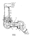
- FIG. 1 shows schematically a remote manipulator 10, of known type, intended to be used for exceptional interventions in the cover gas of a fast neutron reactor vessel, during a cold shutdown of this reactor.
- This remote manipulator 10 is adapted to the ambient radioactivity usually existing in the cover gas.
- the remote manipulator 10 comprises three rigid sections 12,14,16 connected together by two joints 18,20 provided with respective pivot axes 22,24.
- the remote manipulator constitutes an articulated unit.
- the proximal section 12 is called the shoulder
- the middle section 14 is called the arm
- the distal section 16 is called the forearm.
- the shoulder 12 is fixed to a telescopic support 26 of which two cylindrical elements 28, 30 have been shown, the element 28, carrying the shoulder 12, being shown in the retracted position in the element 30.
- the forearm 16 carries on its free end a clamp 32 intended in particular to hold for example a tool or a means of vision, not shown.
- the rigid sections 12, 14, 16 usually comprise members the operation of which is provided for a temperature not exceeding 50 °. Furthermore, the temperature of the cover gas is approximately 150 ° during a cold shutdown of the reactor.
- the remote manipulator is provided with cooling devices according to the invention 34,35,36. These devices respectively comprise rigid enclosures 37, 38, 39, of generally cylindrical shape, surrounding the rigid sections 12, 14, 16, inside of which circulates a heat transfer gas compatible with the covering gas.
- the rigid enclosure 38, surrounding the arm 14, is shown in more detail in Figures 2 and 3 and will be described later.
- the cooling devices 35,36 comprise, in addition to the rigid enclosures 38,39, deformable enclosures or annular bellows 40,42 respectively surrounding the joints 18,20.
- These bellows 40,42 respectively comprise means of communication with the rigid enclosures 38,39, allowing them to be supplied with heat transfer gas, which will be described later.
- the rigid enclosures 12, 14, 16 and the bellows 40, 42 are connected to a pneumatic circuit 44 in which the heat transfer gas circulates in a closed circuit.
- This circuit 44 comprises a compressor 46 discharging the heat transfer gas at a high pressure of approximately 40 bars into an umbilical supply duct 48.
- This duct 48 is connected to a pressure regulator 50 disposed near the parts to be cooled of the manipulator.
- the regulator 50 reduces the pressure of the heat transfer gas to approximately 5 bars.
- the rigid enclosures 37, 38, 39 are respectively supplied with heat transfer gas by flexible supply conduits 52, 54, 56 connected to the outlet of the regulator 50.
- the heat transfer gas is expanded inside the rigid enclosure by means which will be described later.
- Two flexible conduits 58, 60 for discharging the expanded gas from the bellows 40,42 and a flexible conduit 62 for discharging the expanded gas from the rigid enclosure 37 surrounding the shoulder are connected to the same manifold 64 connected to a conduit umbilical discharge 66.
- This duct 66 brings the heat-carrying gas, after its heating, into a refrigeration unit 68 in which it is cooled and then returned through a duct 70 in the compressor 46.
- exothermic members 72, 74, 76 for example motors intended to rotate the rigid sections around their articulations or to actuate a tool, represented schematically by rectangles, are arranged inside. rigid sections 12,14,16.
- Heat shields 78 of generally planar shape, made of insulating material, are arranged on either side of the exothermic members 72, 74, 76, roughly perpendicular to the longitudinal axis of the rigid sections which carry them. These screens hinder the axial propagation of the calories emitted by the exothermic organs. It goes without saying that these screens can have different shapes adapted to the shape of the organs they surround.
- the free end of the forearm 16 comprises a disc 80 of insulating material, arranged perpendicular to the axis of the forearm 16, shielding the axial heat received from the medium and transmitted by the clamp.
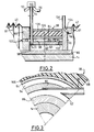
- the rigid enclosure 38 surrounding the arm 14 is shown diagrammatically in FIG. 2. It can be seen in this figure that the enclosure 38 comprises two coaxial cylindrical walls 82, 84, one internal and the other external, disposed around 'a sleeve 86 or box spring covering the wall of the arm 14. These coaxial walls 82,84 extend longitudinally between two end discs 88,90.
- the end discs 88.90 form supports for the annular bellows 40.42.
- One of the two ends of the annular bellows 40 is fitted and fixed to the peripheral edge of the end disc 88 by means not shown.
- one of the two ends of the bellows 42 is fitted and fixed to the peripheral edge of the end disc 90. It can also be seen in FIG. 2 that the bellows 40,42 have reinforcement rings 91 arranged in their waves.
- the internal cylindrical wall 82 delimits an internal chamber 92 between its internal surface and the external surface of the bed base 86.
- the external cylindrical wall 84 coaxial with the internal wall 82, delimits an external chamber 94 between its internal surface and the external surface of the internal wall 82. This wall 82 is adjoining the internal and external chambers 92, 94.
- the internal chamber 92 is connected to the flexible conduit 54 for supplying heat-transfer gas to the enclosure 38 by a conduit 96, extending the latter and opening into the internal chamber 92 by a gas inlet opening 98.
- the external chamber 94 is connected to the volume delimited by the bellows 40 by a communication orifice 100 passing axially through the end disc 88.
- the orifice 100 is an orifice for the admission of heat transfer gas for the bellows 40.
- the dividing wall 82 separating the two chambers 92,94, is provided with orifices 102 forming means for expansion of the gas between these two chambers 92,94.
- These orifices 102 are spaced along the circumference of the party wall 82 and pass radially through the latter. They are also calibrated so as to expand the heat transfer gas, coming from the internal chamber 92, to a pressure close to the pressure of the cover gas, which can be 1 bar, in which the remote manipulator 10 is in operation.
- the gas intake opening 98 and the communication orifice 100 are arranged in the vicinity of the end disc 88, on the left when considering FIG. 2.
- the calibrated orifices 102 are arranged at the other end of the enclosure 38, in the vicinity of the end disc 90, on the right when considering FIG. 2.
- the heat transfer gas circulates, on the one hand in the internal or high pressure chamber 92, in a generally axial direction, from left to right, and, on the other hand, in the external or low pressure chamber 94 in a direction opposite to the previous one, from right to left.
- the gas from the low pressure chamber 94 is sent through the communication orifice 100 in the bellows 40.
- the directions of flow of the gas in the high pressure and low pressure chambers are represented in FIG. 2 by the arrows f1, f2, f3.
- the end disc 90 on which the bellows 42 is fixed, comprises an orifice 104 for discharging the low pressure gas circulating in the bellows 42.
- the direction of flow of the gas through the orifice 104 is represented by arrow f4.
- the orifice 104 is connected, by means not shown, to the flexible conduit 58 for discharging the expanded gas.
- the shoulder 12 and the forearm 16, connected to the arm 12 by the joints 18,20, respectively comprise rigid enclosures 37,39 similar to the enclosure 38 of the arm 14, described above.
- the end of the bellows 40 is fixed to an end disc, similar to the disc 90, carried by the shoulder 14 and provided with a port for discharging the gas towards the outside. bellows.
- the end of the bellows 42 is fixed to a disc, similar to the end disc 88, carried by the forearm 16 and provided with an intake orifice. gas communicating with the low pressure chamber of the enclosure 39 disposed around the forearm 16.
- each bellows 40,42 is formed in a disc secured to a first rigid section and the gas discharge orifice of the bellows is formed in a disc secured to a second rigid section , this section being connected to the first by the joint covered by the bellows.
- the supply of heat transfer gas is independent for each rigid section 12,14,16.
- the enclosure 39 surrounding the forearm 16 is supplied with heat transfer gas through the conduit 56.
- the gas expands in the calibrated orifices of the enclosure 39. It is then sent into the bellows 42, surrounding the joint 20, then outside the bellows 42 in the discharge conduit 58.
- the enclosure 38 surrounding the arm 14 is supplied with heat transfer gas through the conduit 54.
- the expanded gas coming from the low pressure chamber 94 is sent into the bellows 40, surrounding the joint 18, then to the outside of the bellows 40 in the discharge duct 60.
- the enclosure 37 surrounding the shoulder 12 is supplied with heat-carrying gas by the duct 52.
- the gas from the low pressure chamber of the enclosure 37 is sent directly to the discharge conduit 62.
- FIG. 2 The graphical representation of the supply conduit 96 in FIG. 2 does not correspond to reality but allows a better understanding of the circulation of the heat transfer gas in the enclosure 38.
- FIG. 3 represents the actual arrangement of the conduit 96.
- the supply duct 96 opens tangentially into the high pressure chamber 92 so as to avoid the formation of a zone for stopping the heat-carrying gas, on the external surface of the bed base 86, risking causing it to heat up. this.
- the outer wall 84 of the low pressure chamber 94 is covered by two layers 106, 108 of thermal insulation. Similar layers of thermal insulation are placed on the enclosures 37, 39 of the shoulder 12 and the forearm 16.
- the bellows 40, 42 include a non-thermal insulation coating. shown in the figures.
- the cover gas is argon.
- the heat transfer gases compatible with argon it is possible to choose, for example, nitrogen or argon itself.
- the heat transfer gas used is nitrogen, the use of which is well controlled by a person skilled in the art and whose specific heat is higher than that of argon.
- the materials constituting the device according to the invention are compatible with the cover gas (argon) and the heat transfer gas (nitrogen).
- the internal wall 82 and the external wall 84 respectively delimiting the internal chamber 92 and the external chamber 94 are made of austenitic stainless steel.
- the layers 106, 108 of thermal insulators are respectively made of silicone (internal layer) and of stainless steel cloth (external layer) and the bellows 40, 42 include a thermal insulation coating of silicone.
- the remote manipulator 10 is subjected to a radial heat flow originating essentially from the outside of the remote manipulator and its exothermic organs, and to an axial heat flow, the intensity of which is approximately ten times lower than that of the radial heat flow.
- the rigid sections 12, 14, 16 of the manipulator 10 must be kept at a temperature below about 50 ° in order to function properly.
- the layers of thermal insulation arranged around the rigid sections 12, 14, 16 and the thermal insulation coating placed around the bellows 40, 42 shield the flow of radial heat from the outside.
- the calories that pass through the layers of thermal insulation are evacuated by the heat transfer gas circulating in the internal and external chambers of the rigid enclosures. Similarly, the heat transfer gas circulating in the bellows 40,42 cools the joints 18,20.
- the two high and low pressure chambers of the rigid enclosures allow the heat transfer gas to circulate in a limited volume by forming thermal bearings between the interior of the manipulator and the cover gas for the effective cooling of the rigid sections.
- the rigid enclosures are therefore not very bulky and make it possible to conserve, almost entirely, the possibilities of movement of the rigid sections of the manipulator.
- the pressures of the gas in the high and low pressure chambers of the rigid enclosures are determined in particular by its mass flow rate necessary to remove the excess calories and by the dimensions of these chambers.
- the pressure in the low pressure chamber depends in particular on the existence of a connection of this chamber to an adjacent bellows, which is the case of the enclosures surrounding the arm 14 and the forearm 16.
- This latter condition is imposed by the fact that, taking the example of the enclosure 38 surrounding the arm 14, the nitrogen contained in the low pressure chamber 94 is sent into the bellows 40 and that the pressure of nitrogen inside the bellows must be limited in relation to the medium pressure, for example the pressure difference between the inside and the outside of the bellows must not exceed 0.5 bar.
- the reinforcement rings 91 arranged in the waves of the bellows 40, 42 make it possible to overcome the effects due to the pressure difference on either side of the wall of the bellows.
- the nitrogen circulating in the rigid enclosures 37, 38, 39 makes it possible, on the one hand, to absorb the calories from the radial flow of heat coming from the covering gas, and on the other hand, to absorb the calories from the radial flow of heat from exothermic organs, such as motors, arranged inside the rigid sections 12,14,16.
- the axial propagation of calories is slowed down in particular by the heat shields arranged in the axis of the hot organs carried by the remote manipulator.
- the disc 80 made of insulating material protects the forearm 16 by shielding the axial heat flows generated by the heating of the clamp 32 or by a tool carried by this clamp.
- the thermal screens 78 arranged in the axis of the rigid sections, on either side of the motors, reduce the axial propagation of the calories emitted by these motors.
- the nitrogen ciciculating in the bellows of the manipulator joints also reduces the axial heat flow propagated by these joints.
- Heat transfer gas supply pipes 52,54,56 and the delivery conduits of this expanded gas 58,60,62 are connected to the same pneumatic circuit 44 closed in order to avoid any release of heat-carrying gas in the covering gas.
- the device according to the invention makes it possible to adapt a remote manipulator to perform exceptional interventions in the cover gas of a fast neutron reactor.
- the invention makes it possible to maintain the rigid sections of the manipulator at a temperature lower than that of the covering gas, adapted to their operation, by avoiding the formation of temperature gradients resulting from local cooling.
- the device according to the invention can be adapted to existing remote manipulators and makes it possible to considerably extend their applications.
- the pressure and flow parameters of the heat transfer gas circulating in the device according to the invention are adjustable as a function of the temperature of the cover gas and of the maximum operating temperature of the remote manipulator.
- the invention is not limited to use in the cover gas of a fast neutron reactor. It also applies to hostile, confined environments, in the presence of a high temperature, radiation or any other unusual condition requiring confinement and cooling of the manipulator.
- the invention is not limited to sections and rigid enclosures of circular sections.
- the invention can be applied to a manipulator comprising a simple pole.
Landscapes
- Engineering & Computer Science (AREA)
- Robotics (AREA)
- Mechanical Engineering (AREA)
- Manipulator (AREA)
Applications Claiming Priority (2)
| Application Number | Priority Date | Filing Date | Title |
|---|---|---|---|
| FR9111999A FR2681977B1 (fr) | 1991-09-30 | 1991-09-30 | Dispositif de refroidissement adaptable sur un telemanipulateur et son utilisation pour une intervention dans un milieu hostile a temperature elevee. |
| FR9111999 | 1991-09-30 |
Publications (1)
| Publication Number | Publication Date |
|---|---|
| EP0536016A1 true EP0536016A1 (de) | 1993-04-07 |
Family
ID=9417420
Family Applications (1)
| Application Number | Title | Priority Date | Filing Date |
|---|---|---|---|
| EP92402524A Withdrawn EP0536016A1 (de) | 1991-09-30 | 1992-09-15 | Kühleinrichtung für Telemanipulator und seine Anwendung für eine Intervention in feindlichem Bereich unter hoher Temperatur |
Country Status (4)
| Country | Link |
|---|---|
| US (1) | US5345480A (de) |
| EP (1) | EP0536016A1 (de) |
| JP (1) | JP3330397B2 (de) |
| FR (1) | FR2681977B1 (de) |
Families Citing this family (6)
| Publication number | Priority date | Publication date | Assignee | Title |
|---|---|---|---|---|
| DE9109502U1 (de) * | 1991-07-31 | 1992-05-14 | Hps Drehmaschinen Gmbh & Co. Kg, 5970 Plettenberg, De | |
| DE10013721A1 (de) * | 2000-03-21 | 2001-09-27 | Guenther Battenberg | Verfahren und Vorrichtung zur Klimatisierung von Robotern |
| SE0202211L (sv) * | 2002-07-11 | 2004-01-12 | Abb Ab | Anordning hos industrirobot |
| DE102010063223A1 (de) * | 2010-12-16 | 2012-06-21 | Robert Bosch Gmbh | Einrichtung zum Abführen von Wärme aus einer automatisierten Handhabungseinrichtung, insbesondere einem Handhabungsroboter, und Verwendung der Einrichtung |
| GB2532719B (en) | 2014-11-20 | 2020-11-11 | Cmr Surgical Ltd | Cooling a surgical robotic arm |
| JP2017127914A (ja) * | 2016-01-19 | 2017-07-27 | セイコーエプソン株式会社 | ロボット及びロボットシステム |
Citations (4)
| Publication number | Priority date | Publication date | Assignee | Title |
|---|---|---|---|---|
| DE2851958A1 (de) * | 1977-12-06 | 1979-06-07 | Vyzk Vyvojovy Ustav Elektric | Elektrisch getriebener mechanischer arm eines industrieroboters |
| EP0245530A1 (de) * | 1986-05-12 | 1987-11-19 | Cincinnati Milacron Inc. | Industriemanipulator |
| DE3728099A1 (de) * | 1986-09-01 | 1988-03-03 | Asea Ab | Nahtfuehrungsgeraet fuer einen industrieroboter |
| EP0447881A1 (de) * | 1990-03-21 | 1991-09-25 | Siemens Aktiengesellschaft | Industrieroboter |
Family Cites Families (4)
| Publication number | Priority date | Publication date | Assignee | Title |
|---|---|---|---|---|
| FR2469779A1 (fr) * | 1979-11-16 | 1981-05-22 | Commissariat Energie Atomique | Dispositif de refroidissement de secours du coeur d'un reacteur a eau pressurisee |
| DE3103299C2 (de) * | 1981-01-31 | 1985-04-04 | Klein, Schanzlin & Becker Ag, 6710 Frankenthal | Abdichtung für Leitungsdurchführungen |
| US4577127A (en) * | 1983-12-21 | 1986-03-18 | Westinghouse Electric Corp. | Lightweight electric robotic actuator |
| FR2603131B1 (fr) * | 1986-08-20 | 1990-12-07 | Novatome | Dispositif de refroidissement de secours d'un reacteur nucleaire a neutrons rapides |
-
1991
- 1991-09-30 FR FR9111999A patent/FR2681977B1/fr not_active Expired - Fee Related
-
1992
- 1992-09-15 EP EP92402524A patent/EP0536016A1/de not_active Withdrawn
- 1992-09-28 US US07/951,793 patent/US5345480A/en not_active Expired - Fee Related
- 1992-09-30 JP JP26190992A patent/JP3330397B2/ja not_active Expired - Fee Related
Patent Citations (4)
| Publication number | Priority date | Publication date | Assignee | Title |
|---|---|---|---|---|
| DE2851958A1 (de) * | 1977-12-06 | 1979-06-07 | Vyzk Vyvojovy Ustav Elektric | Elektrisch getriebener mechanischer arm eines industrieroboters |
| EP0245530A1 (de) * | 1986-05-12 | 1987-11-19 | Cincinnati Milacron Inc. | Industriemanipulator |
| DE3728099A1 (de) * | 1986-09-01 | 1988-03-03 | Asea Ab | Nahtfuehrungsgeraet fuer einen industrieroboter |
| EP0447881A1 (de) * | 1990-03-21 | 1991-09-25 | Siemens Aktiengesellschaft | Industrieroboter |
Also Published As
| Publication number | Publication date |
|---|---|
| JP3330397B2 (ja) | 2002-09-30 |
| JPH05245790A (ja) | 1993-09-24 |
| FR2681977A1 (fr) | 1993-04-02 |
| US5345480A (en) | 1994-09-06 |
| FR2681977B1 (fr) | 1993-12-31 |
Similar Documents
| Publication | Publication Date | Title |
|---|---|---|
| RU2301727C2 (ru) | Вакуумная печь для пайки давлением и способ ее использования | |
| CH690506A5 (fr) | Soupage d'échappement sous vide. | |
| EP0536016A1 (de) | Kühleinrichtung für Telemanipulator und seine Anwendung für eine Intervention in feindlichem Bereich unter hoher Temperatur | |
| CA2070506A1 (fr) | Dispositif de refroidissement d'une goulotte de distribution d'une installation de chargement d'un four a cuve | |
| CA1231997A (fr) | Systeme d'etoupage pour electrodes | |
| FR2967231A1 (fr) | Dispositif de raccordement destine a se raccorder a au moins une canalisation | |
| FR2842277A1 (fr) | Raccord tournant cryotechnique et application notamment a des lignes d'alimentation de fluide articulees et a des moteurs-fusees a ergols cryogeniques | |
| EP0679852B1 (de) | Einrichtung zur Druckbeaufschlagung eines Plattenstapels, insbesondere für Plattenwärmetauscher | |
| EP0020265A1 (de) | Wärmeaustauscher für Kernreaktor | |
| EP3721452A1 (de) | Lagerkorb zum lagern oder transportieren von kernmaterialien | |
| EP3535479B1 (de) | Kühlvorrichtung für eine turbine einer turbomaschine | |
| FR2903151A1 (fr) | Dispositif de ventilation d'un carter d'echappement dans une turbomachine | |
| FR2991736A1 (fr) | Dispositif d'etancheite d'une pompe | |
| FR2540971A1 (fr) | Generateur de vapeur pour un reacteur nucleaire refroidi par du metal liquide | |
| EP0740767B1 (de) | Wärmetauscher für kontaminierte flüssigkeit | |
| FR2607874A1 (fr) | Dispositif de sortie d'arbre pour pompe a eau sous hautes pression et temperature, notamment pour pompe alimentaire de centrale electrique a vapeur | |
| FR2555794A1 (fr) | Reacteur nucleaire a neutrons rapides equipe de moyens de refroidissement de secours | |
| FR1465587A (fr) | Piège froid à vanne incorporée pour circuit de vide | |
| EP0024990B1 (de) | Vorrichtung zum Transport bestrahlten Kernbrennstoffs durch die Abdeckplatte eines Kernreaktors hindurch | |
| FR2674616A1 (fr) | Systeme cryogenique pour missiles. | |
| EP0509926B1 (de) | Einrichtung zur biologischen Abschirmung eines Kreislaufelements für radioaktive Flüssigkeit | |
| CH615477A5 (en) | Device for the thermal insulation of a prestressed concrete vessel | |
| EP0363247B1 (de) | Vorrichtung zum Anbringen und Entfernen eines Plasmabrenners in einen Apparat, der unter einem solchen Druck und einer solchen Temperatur arbeitet, dass direktes Arbeiten unmöglich ist | |
| FR2481507A1 (fr) | Dispositif de reduction des contraintes thermiques dans le fond d'un echangeur de chaleur vertical | |
| FR3019931A1 (fr) | Unite de chargement / dechargement d'assemblages combustibles d'un reacteur refroidi au metalliquide, tel qu'un reacteur rnr-na ou sfr, integrant un dispositif de mesure de la puissance residuelle |
Legal Events
| Date | Code | Title | Description |
|---|---|---|---|
| PUAI | Public reference made under article 153(3) epc to a published international application that has entered the european phase |
Free format text: ORIGINAL CODE: 0009012 |
|
| 17P | Request for examination filed |
Effective date: 19930204 |
|
| AK | Designated contracting states |
Kind code of ref document: A1 Designated state(s): DE GB |
|
| 17Q | First examination report despatched |
Effective date: 19950320 |
|
| STAA | Information on the status of an ep patent application or granted ep patent |
Free format text: STATUS: THE APPLICATION HAS BEEN WITHDRAWN |
|
| 18W | Application withdrawn |
Withdrawal date: 19951007 |