EP0535501A2 - Dust removal plant for machines - Google Patents
Dust removal plant for machines Download PDFInfo
- Publication number
- EP0535501A2 EP0535501A2 EP92116141A EP92116141A EP0535501A2 EP 0535501 A2 EP0535501 A2 EP 0535501A2 EP 92116141 A EP92116141 A EP 92116141A EP 92116141 A EP92116141 A EP 92116141A EP 0535501 A2 EP0535501 A2 EP 0535501A2
- Authority
- EP
- European Patent Office
- Prior art keywords
- suction
- blowing
- air
- opening
- shafts
- Prior art date
- Legal status (The legal status is an assumption and is not a legal conclusion. Google has not performed a legal analysis and makes no representation as to the accuracy of the status listed.)
- Withdrawn
Links
Images

Classifications
-
- D—TEXTILES; PAPER
- D03—WEAVING
- D03J—AUXILIARY WEAVING APPARATUS; WEAVERS' TOOLS; SHUTTLES
- D03J1/00—Auxiliary apparatus combined with or associated with looms
- D03J1/002—Climatic conditioning or removing lint or dust
-
- B—PERFORMING OPERATIONS; TRANSPORTING
- B01—PHYSICAL OR CHEMICAL PROCESSES OR APPARATUS IN GENERAL
- B01D—SEPARATION
- B01D46/00—Filters or filtering processes specially modified for separating dispersed particles from gases or vapours
-
- B—PERFORMING OPERATIONS; TRANSPORTING
- B08—CLEANING
- B08B—CLEANING IN GENERAL; PREVENTION OF FOULING IN GENERAL
- B08B5/00—Cleaning by methods involving the use of air flow or gas flow
Definitions
- the invention relates to a system for the automatic dedusting of a machine during its workflow, from which the dust can be removed, which is located both on the machine and in its environment and on and / or between certain difficult-to-reach individual parts of the machine;
- this system consists mainly of an aspirator, which draws in air contaminated with dust and / or other waste with the aid of suction openings, a filter device in which the dust and / or other waste is separated from the intake air, and a blowing device, which creates a directed air flow with the help of blowing openings, which takes the dust with it and introduces it within the suction area of at least one suction opening.
- a problem underlying this invention is the fact that the accumulation of dust on a machine and on or between certain parts of that machine can result in the poor operation of the machine and / or the poor quality of the manufactured product, so that the machine must be stopped regularly to remove the dust. If a machine comes to a standstill, production naturally stops. The repetitive cleaning work consequently causes a great reduction in the efficiency of the machine.
- Another problem underlying this invention is the fact that in the vicinity of some machines (e.g. textile machines, woodworking machines and the like) dust particles are floating around in large quantities; as a result, the people who work in the vicinity of these machines, and in particular the people who operate these machines, must work in an unpleasant environment; above all, these people still inhale large amounts of dust every day, which sooner or later affects their health.
- some machines e.g. textile machines, woodworking machines and the like
- warp threads run in a weaving machine side by side from back to front. These warp threads are unrolled from the back of one or more trees and extend mainly horizontally to the front.
- a weaving machine is provided with a device for introducing weft threads in the transverse direction to the warp threads, which happens after a compartment has been formed between these warp threads.
- Certain warp threads must therefore be pulled up or down in the vertical direction for each weft. This is done with the help of so-called stems.
- stems These are rectangular, vertically arranged frames that are provided with lifts that themselves have eyes. Warp threads are pulled through different eyes.
- Several shafts are arranged one behind the other so that the upward or downward movement of a shaft results in an upward or downward pull of a certain group of warp threads. During the weaving process, the closely spaced shafts continuously move up and down to one another.
- the weaving machine is provided with a reed which extends over the full width of the fabric and, as a result of a forward and backward movement after each weft, brings the weft thread that has just been introduced against the fabric edge - the previous weft thread.
- a large amount of dust is whirled up during the weaving process, which partly consists of fibers that come from the threads. This floats around in the surrounding air and collects about anywhere on or on the weaving machine and between its various individual parts. Above all, a lot of dust is deposited between the shafts, where after a certain time it clumps into balls that get caught between the shafts. In the first possible situation, these balls pile up on each other and get stuck in the shafts. The warp threads finally get into these skeins, which makes them coherent and ultimately tear.
- a skein is taken along by a warp thread and consequently gets into the weaving area, as a result of which dust escapes from the fabric.
- the whirling dust especially the dust that suddenly swirls between the shafts in large, possibly agglomerated quantities, gets between the warp and weft threads and is woven into the fabric, which causes errors. This is inadmissible, so that the machine must be shut down regularly for cleaning, which results in loss of production.
- a first known cleaning system consists of a so-called robot for suction and blowing. It relates to a device which consists mainly of a fan which is slidably mounted on a rail moored above different weaving machines, the system being designed, for example, in such a way that the automatically extending device arrives one after the other above all the weaving machines at the same work station.
- the fan blows by means of a first downward-hanging arm with a horizontally directed blowing opening, which is suspended at a certain height in front of the weaving machines, while it is blown by means of a second downward-hanging arm with a suction opening, which is suspended along the floor is sucking in air and dust.
- the dust lying on the machine is blown away and whirled up and finally falls to the floor, from where it is sucked up through the suction opening.
- a first disadvantage of this device consists in the fact that the air flow reaches the outer surface of the machine one by one and thus will only remove the dust in those places.
- the dust particles that are in the shafts of the weaving machine or in other parts that are not easily accessible will certainly not be eliminated with this facility; Therefore, this device only cleans the surface of the machine, while the dust on or between the individual parts, where it is most heavily accumulated, is not removed.
- Another disadvantage of this known device consists of the complaint for the operator of the machine, which is caused by the arms hanging down.
- Another known dedusting system for weaving machines consists of a suction cap arranged above the warp thread monitors in connection with a suction system.
- the rising air flow takes the upward flying dust with it.
- the disadvantage of this device again consists in the fact that the dust particles which are deposited on or between the shafts or which are inaccessible to other locations of the weaving machine for the rising air flow are not removed; As a result, on the one hand, the weaving machine still has to be shut down for thorough cleaning work, and on the other hand, the upward flying dust particles, which from other places (e.g. between the weaving machine and the weaving frame) still contaminate the surroundings of the workplace, which has a detrimental effect on the Personnel health.
- the aim of the invention is to provide a dedusting system for a machine with which a remedy for the above-mentioned disadvantages becomes.
- An object of the invention is a dedusting system for a machine, which consists of a suction device for air contaminated with dust and / or waste, a filter device from which the suctioned air is filtered, and a blowing device.
- a suction device for air contaminated with dust and / or waste
- a filter device from which the suctioned air is filtered
- a blowing device One or more suction devices are connected to the suction device, and one or more blowing openings are connected to the blowing device.
- One or more blowing openings are arranged opposite one or more suction openings in such a way that the air blown out of the blowing openings creates an air flow in an open space, which is directed towards the most accessible, moving individual parts and prevents the dust particles from clumping together. fall down and settle on those individual parts, whereby these dust particles are transported to the suction openings.
- An essential feature of the invention consists in the fact that the air flow is generated in an open space.
- the purpose of this is that between the blowing and suction openings no construction of aids is to be provided which enclose the air flow in whole or in part or which guide this air flow in any way.
- the mixture of air and dust particles, which was mixed using the suction opening, is cleaned by a filter device, possibly cooled and returned to the work area.
- blowing and suction openings can each be connected to a separate device - suction device - or blowing device - and can be supplied with air separately from one another.
- the sucked-in air which entrains the dust and / or other waste, is filtered in a filter device and possibly cooled, and then the filtered air is fed directly to the blowing openings for reuse.
- a known filter device is used.
- a filter device can be used, the mode of operation of which is based on the principle of the filter, which is explained in Belgian Patent No. 08901086.
- a particular embodiment of the invention is a dedusting system for a machine, which consists of an aspirator with which air laden with dust and / or waste can be sucked in through one or more suction openings, a filter device not necessarily installed in this device filtering the suction air can, so that on the one hand the dust and / or other waste gets into a designated receptacle and on the other hand the clean air is blown back through one or more blowing openings, which generate an air flow that takes the floating dust particles with them and leads them to one or more suction openings.
- the dedusting system according to the invention consists of one or more suction openings connected to the suction part of the aspirator and one or more blowing openings connected to the blowing section of the aspirator.
- the air In order to generate an air stream in the form of a curtain, the air should be blown evenly through a narrow, directed gap over the entire width of the machine parts that are as easily accessible and moving (e.g. over the entire width of the shafts of a weaving machine).
- Blow openings of a known shape have the disadvantage of distributing the air unevenly at the outlet.
- a special blowing opening was developed to achieve this uniform distribution.
- Another object of the invention is the special blow opening developed for the above application.
- the blowing opening according to the invention consists of a space enclosed by walls, which has a restricted supply opening for connection to the line leading to the air and an elongated, gap-shaped outflow opening through which the air is blown out evenly.
- the space enclosed by the walls has a section at the height of the supply opening - that is perpendicular to the direction of flow of air into that space runs - which is larger than the section of the supply line. The further one gets in the direction of the outflow opening, the more this section increases to a maximum, and from there it decreases back to reach a minimum near the outflow opening, which remains the same up to the outflow opening .
- a preferred embodiment of the dedusting system and its well-defined arrangement with regard to the individual machine parts can, however, be described exactly using an exemplary embodiment.
- the following is one Weaving machine of known construction considered, which is equipped with a dedusting system according to the invention.
- the dedusting system according to the invention comprises an aspirator (1) for drawing in air, which is provided with one or more openings through which the air is drawn into this aspirator (1) and one or more openings through which the sucked-in air comes out the aspirator (1) is blown back, while lines can be connected to those openings. Furthermore, a filter device (2) is provided in the dedusting system according to the invention, from which dust or other waste carried along by the sucked-in air is filtered out of this air in a generally known manner (see Belgian Patent No. 08901086), that on the one hand the dust or other waste is deposited in a designated container (3) and on the other hand the filtered air is blown out.
- This filter device (2) is consequently arranged in such a way that all the air drawn in must move through this filter device (2) before it is blown out, and can either be installed in the aspirator (1) or through a line in which all the air drawn in passes will be connected to the aspirator (1), while another line connected to this filter device (2) leads the filtered air further through the system so that it is finally blown out.
- the dedusting system according to the invention also contains a suction opening (4) with a rectangular feed opening which has approximately the same length as the width of the shafts (5).
- This suction opening (4) the supply opening of which is directed upwards, is arranged horizontally on the rear of the shafts (5) nearby in such a way that it extends parallel to the shafts (5) and over their entire width.
- This suction opening (4) is connected to a suction opening of the aspirator (1) with the aid of a line (4 ').
- the dedusting system according to the invention also has a row of blowing openings (7) according to the invention, which are arranged in a horizontal row as close as possible to one another immediately in front of the stems (5), their outlet opening (9) to the stems (5 ) is directed and this row extends parallel to the shafts (5) and preferably over almost the full width of these shafts (5).
- These blow holes (7) are connected by means of lines (7 ') to one or more blowing openings of the aspirator (1).
- blow openings (7) are specially designed for this application and represent an object of the invention (see FIGS. 5a and 5b).
- the blowing opening (7) consists of a box-shaped unit composed of flat walls, in which an inlet opening (8) and an outlet opening (9) for the air are provided, and which is subsequently explained in FIGS. 5a and 5b has the shape shown.
- a flat top wall (10) or base wall (11) and two side walls (12) adjoin the four sides of the rectangular, flat rear wall, the top wall (10) and the base wall (11) on the one hand and the two side walls on the other (12) symmetrically further apart from each other.
- edges of the walls of the blowing opening (7) which end at the front, form a rectangular front of low height and great width (equal to the width of the blowing opening (7)). This front is not closed, but forms the exit opening (9) of the blowing opening (7).
- edge part (13) and (14) are fastened parallel to one another in the width direction of the blowing opening (7) and one of which edge part (13) is stuck and the other edge part ( 14) is adjustable in height and z. B. can be fixed with a screw in the blow opening (7).
- the two edge parts have a bent section running in their respective direction.
- a continuous, straight, profiled rail (15) is horizontally in front the shafts (5) attached.
- This rail (15) has a vertically standing wing (15 ') of the same height throughout its entire length and a vertical downward wing (15'') of the same height along the entire length.
- the vertical distance between the edges of the two wings (15 ') and (15'') corresponds to the vertical distance between the projecting edge parts (13) and (14) so that the blowing opening (7) is displaced on the rail (15) can be, wherein the bent portion of the upper edge part (14) hooks behind the upper edge of the wing (15 ') and the bent portion of the lower edge part (13) hooks behind the lower edge of the wing (15'').
- the blow opening (7) can be moved to the desired position on the rail (15).
- the blowing opening (7) is arranged so that it cannot move and is stable.
- the inlet opening (8) is located in the base wall (11) close to the rear of the blowing opening (7). Along this opening (8), the air enters the interior of the blowing opening (7) enclosed by the walls (10), (11) and (12). Inside the blowing opening (7), the air flows in the direction of the exit opening (9), where it leaves the blowing opening (7).
- the shape of the interior enclosed by the walls (10), (11) and (12) now provides the desired advantage of the invention.
- This shape is dimensioned such that a vertical cross section through the blow opening (7) - parallel to the rear wall - has an area at the height of the feed opening (8) which is larger than the section of the feed opening (8).
- the air that flows out of the supply opening (8) suddenly receives a larger section - perpendicular to the flow direction.
- This section increases further if you always go in the direction of the exit opening (9) (the walls are separated from each other), and one reaches a maximum at the height of the rear bend in those walls. During its passage through the blow opening (7), the air has thus got a gradually increasing flow cross-section and has consequently been able to expand. The flow rate has decreased, and the pressure, which at the high speed is not very even was distributed over the entire cross-section (close to the walls it is smaller than in the middle) receives a more uniform distribution.
- the air flow rate will thus gradually increase up to the blowing speed.
- the pressure increases gradually and is given the opportunity to be distributed evenly over the long, narrow cross-section.
- the suction opening (4) is now arranged in such a way that the air curtain is directed onto the shafts (5).
- the air flow takes the floating particles with them in their flow and conveys them to the suction opening (4).
- Almost all air that was blown out of the blowing openings (7) is sucked back together with the dust carried in that way through the suction opening (4).
- This air is filtered in the filter device (2) and blown out again from the blowing openings (7).
- most of the air describes a cycle, which is a further discussed advantage of the invention.
- suction openings (16), (17) which are arranged at two different locations with respect to the weaving machine.
- the suction opening (16) is designed in the form of a cap with a rectangular supply opening, which, directed downwards, is arranged horizontally in front of the shafts (5) and is connected to a suction opening of the aspirator via a line (16 '). In this way, the rising dust is also removed from the space in front of the shafts (5) during the work cycle of the weaving machine in order to be finally deposited in the collecting container (3) via the filter device (2).
- a suction opening (17) for sucking up these cut edges is always arranged at the level at which the two fabric edges are cut off.
- This waste which until today is mechanically discharged to a separate waste container, also ends up in the common waste container (3) of the weaving machine.
- a double piece weaving machine also creates a significant amount of dust where the top and bottom fabrics are separated when the pile threads are cut. This is done with a fast reciprocating knife that cuts a row of pile threads with every movement.
- the dust which mainly consists of fibers from the cut threads, is taken to the side edges of the fabric.
- the dedusting system according to the invention can be supplemented at those locations (on the opposite sides of the knife path) by added suction openings (not shown in the figures) which also suck up this dust and via a line which was connected to a suction opening of the aspirator (1) , deposit in the collecting container (3).
- An advantage of the dedusting system according to the invention lies above all in the fact that the shafts (5) are dedusted by the production of a directed air curtain during the working process of the weaving machine. As a result, there is practically no flying dust whirling freely, because this dust is inside the air curtain and is sucked off directly from a suction opening (4). The shafts (5) remain dust-free. The resistances of strands of dust in the fabric are switched off and the machine for dust removal is no longer necessary.
- An additional advantage of the dedusting system according to the invention lies in the fact that no air is sucked in outside the workplace. Most of the air blown out of the blowing openings (7) is sucked back through the suction opening (4), filtered and returned to the blowing openings.
- blowing openings (7) make a significant contribution to the good functioning of the dedusting system by making it possible to produce a wide, fast-moving air curtain at a uniform speed over the entire width.
- the air curtain produced according to the invention runs best by the shortest route, that is to say in a horizontal plane, through the openings of the shafts. After sweeping over a transverse packing 20, which is rounded toward the lower-lying suction opening 4, the air flow is then grasped by the suction flow and sucked into the suction openings 4 directed vertically upwards. If, on the other hand, you would, as usual, direct the horizontal air flow directly into the suction opening to be opened onto the air flow in a suction chamber accordingly placed in the air flow, serious installation space problems would arise in this area.
- the suction device can be relocated to a lower lying and therefore less critical area. This also results in a favorable flow guidance, especially since the intake cross section lying in the horizontal plane can advantageously be selected to be large.
- the invention relates to a system for the automatic dedusting of a machine during its work, comprising a suction device (1), a filter device (2) and a blowing device (1), while blowing openings (7) connected to the blowing device (1) are arranged in this way that the escaping air flow is directed towards the most accessible and moving dust-producing parts (5) of that machine, and that this air flow takes the floating dust particles to a suction opening (4) connected to the suction device (1) and conveys them while the sucked-in air with dust is led to a filter device (2) and the clean air is possibly blown back into the work area via the blower openings (7).
- a blowing opening (7) has a restricted supply opening and a wider interior, which first has a gradually increasing cross-section in the direction of flow of the air, which is followed by a gradually decreasing cross-section in order to reach a gap-shaped outlet opening (9), as a result of which the air flow generated, evenly distributed, leaves the blow opening (7) via the outlet opening (9).
Abstract
Description
Die Erfindung betrifft eine Anlage zum selbsttätigen Entstauben einer Maschine während ihres Arbeitsablaufes, von der der Staub entfernt werden kann, der sich sowohl auf der Maschine und in ihrer Umgebung als auch an und/oder zwischen bestimmten, schwer zu erreichenden Einzelteilen der Maschine befindet; dabei besteht diese Anlage hauptsächlich aus einem Aspirator, der mit Hilfe von Ansaugöffnungen mit Staub und/oder anderem Abfall belastete Luft ansaugt, aus einer Filtereinrichtung, in der der Staub und/oder andere Abfall von der angesaugten Luft abgetrennt wird, und aus einer Blasvorrichtung, die mit Hilfe von Blasöffnungen einen gerichteten Luftstrom erzeugt, der den Staub mitnimmt und innerhalb des Ansaugbereiches von mindestens einer Ansaugöffnung einbringt.The invention relates to a system for the automatic dedusting of a machine during its workflow, from which the dust can be removed, which is located both on the machine and in its environment and on and / or between certain difficult-to-reach individual parts of the machine; this system consists mainly of an aspirator, which draws in air contaminated with dust and / or other waste with the aid of suction openings, a filter device in which the dust and / or other waste is separated from the intake air, and a blowing device, which creates a directed air flow with the help of blowing openings, which takes the dust with it and introduces it within the suction area of at least one suction opening.
Ein Problem, das dieser Erfindung zugrundeliegt, ist die Tatsache, daß die Anhäufung von Staub auf einer Maschine und an oder zwischen bestimmten Einzelteilen dieser Maschine den schlechten Arbeitsablauf der Maschine und/oder die weniger gute Qualität des angefertigten Produktes zur Folge haben kann, so daß zur Entfernung des Staubes ein regelmäßiges Anhalten der Maschine notwendig ist. Der Stillstand einer Maschine hat natürlich ein Aussetzen der Produktion zur Folge. Die sich wiederholenden Reinigungsarbeiten verursachen folglich eine starke Verminderung des Wirkungsgrades der Maschine.A problem underlying this invention is the fact that the accumulation of dust on a machine and on or between certain parts of that machine can result in the poor operation of the machine and / or the poor quality of the manufactured product, so that the machine must be stopped regularly to remove the dust. If a machine comes to a standstill, production naturally stops. The repetitive cleaning work consequently causes a great reduction in the efficiency of the machine.
Ein weiteres, dieser Erfindung zugrundeliegendes Problem ist die Tatsache, daß in der Umgebung einiger Maschinen (z. B. von Textilmaschinen, holzverarbeitenden Maschinen und dgl.) ständig Staubteilchen in großer Menge herumschweben; infolgedessen müssen die Menschen, die in der Umgebung dieser Maschinen arbeiten, und insbesondere die Menschen, die diese Maschinen bedienen, in einem unangenehmen Milieu arbeiten; vor allem atmen diese Menschen täglich noch große Mengen Staub ein, wodurch früher oder später ihre Gesundheit angegriffen wird.Another problem underlying this invention is the fact that in the vicinity of some machines (e.g. textile machines, woodworking machines and the like) dust particles are floating around in large quantities; as a result, the people who work in the vicinity of these machines, and in particular the people who operate these machines, must work in an unpleasant environment; above all, these people still inhale large amounts of dust every day, which sooner or later affects their health.
Da man in der Industrie ein ständig zunehmendes Interesse der Verbesserung der Arbeitsbedingungen zukommen läßt, drängt sich auch eine Lösung dieses Problems auf.Since there is a growing interest in improving working conditions in the industry, a solution to this problem is inevitable.
Webmaschinen gehören zu denjenigen Maschinen, bei denen die obengenannten Probleme auftreten. In einer Webmaschine läuft eine große Zahl Kettfäden nebeneinander von hinten nach vorn. Diese Kettfäden werden hinten von einem oder mehreren Bäumen abgerollt und erstrecken sich hauptsächlich horizontal nach vorn.Weaving machines are among those machines that experience the above problems. A large number of warp threads run in a weaving machine side by side from back to front. These warp threads are unrolled from the back of one or more trees and extend mainly horizontally to the front.
Ferner ist eine Webmaschine mit einer Einrichtung zum Einbringen von Schußfäden in Querrichtung zu den Kettfäden versehen, was geschieht, nachdem zwischen diesen Kettfäden ein Fach gebildet wurde. Für jeden Schuß müssen somit bestimmte Kettfäden in vertikaler Richtung nach oben oder unten gezogen werden. Dies geschieht mit Hilfe sog. Schäfte. Dies sind rechteckige, vertikal angeordnete Rahmen, die mit Hebern versehen sind, die selbst Augen aufweisen. Durch verschiedene Augen hindurch werden Kettfäden gezogen. Mehrere Schäfte werden hintereinander angeordnet, so daß die Auf- oder Abwärtsbewegung eines Schaftes einen Auf- oder Abwärtszug einer bestimmten Gruppe Kettfäden zur Folge hat. Während des Webvorganges bewegen sich die dicht hintereinander stehenden Schäfte fortwährend zueinander auf- und abwärts. Ferner ist die Webmaschine mit einem Riet versehen, das sich über die vollständige Breite des Gewebes erstreckt und infolge einer Vor- und Rückwärtsbewegung nach jedem Schuß den gerade eingebrachten Schußfaden gegen den Geweberand - den vorherigen Schußfaden - bringt. Infolge all dieser sich schnell bewegenden Einzelteile und Fäden wird während des Webvorganges eine große Menge Staub aufgewirbelt, die zum Teil aus Fasern besteht, die aus den Fäden stammen. Dieser schwebt in der Luft der Umgebung umher und sammelt sich etwa überall auf oder an der Webmaschine und zwischen deren unterschiedlichen Einzelteilen. Vor allem wird viel Staub zwischen den Schäften abgelagert, wo er sich nach einer gewissen Zeit zu Knäueln zusammenballt, die zwischen den Schäften hängenbleiben.Bei einer ersten möglichen Situation häufen sich diese Knäuel aufeinander und bleiben in den Schäften stecken. Die Kettfäden gelangen schließlich in diese Knäuel, wodurch sie zusammenhängen und schließlich reißen.Furthermore, a weaving machine is provided with a device for introducing weft threads in the transverse direction to the warp threads, which happens after a compartment has been formed between these warp threads. Certain warp threads must therefore be pulled up or down in the vertical direction for each weft. This is done with the help of so-called stems. These are rectangular, vertically arranged frames that are provided with lifts that themselves have eyes. Warp threads are pulled through different eyes. Several shafts are arranged one behind the other so that the upward or downward movement of a shaft results in an upward or downward pull of a certain group of warp threads. During the weaving process, the closely spaced shafts continuously move up and down to one another. Furthermore, the weaving machine is provided with a reed which extends over the full width of the fabric and, as a result of a forward and backward movement after each weft, brings the weft thread that has just been introduced against the fabric edge - the previous weft thread. As a result of all these rapidly moving individual parts and threads, a large amount of dust is whirled up during the weaving process, which partly consists of fibers that come from the threads. This floats around in the surrounding air and collects about anywhere on or on the weaving machine and between its various individual parts. Above all, a lot of dust is deposited between the shafts, where after a certain time it clumps into balls that get caught between the shafts. In the first possible situation, these balls pile up on each other and get stuck in the shafts. The warp threads finally get into these skeins, which makes them coherent and ultimately tear.
Bei einer anderen möglichen Situation wird ein Knäuel von einem Kettfaden mitgenommen und gelangt folglich in den Webbereich, wodurch aus dem Gewebe Staub austritt.In another possible situation, a skein is taken along by a warp thread and consequently gets into the weaving area, as a result of which dust escapes from the fabric.
Oberhalb der Webmaschinen tritt in der Höhe der Schäfte eine Art Schaueffekt auf, bei dem andauernd eine große Menge Staub oberhalb der Webmaschine aufsteigt. Dieser Staub verursacht gemeinsam mit dem Staub, der aus den Schäften oder woanders her aufwirbelt, eine Verschmutzung der Luft an dem Arbeitsplatz.Above the weaving machines, a kind of viewing effect occurs at the height of the shafts, in which a large amount of dust constantly rises above the weaving machine. This dust, together with the dust whirling up from the shafts or elsewhere, causes air pollution in the workplace.
Der aufwirbelnde Staub, vor allem derjenige Staub, der plötzlich zwischen den Schäften in großen, eventuell zusammengeballten Mengen aufwirbelt, gerät zwischen die Kett- und Schußfäden und wird in das Gewebe eingewebt, in dem dadurch Fehler entstehen. Dies ist unzulässig, so daß die Maschine regelmäßig zur Reinigung stillgesetzt werden muß, was Produktionsverluste zur Folge hat.The whirling dust, especially the dust that suddenly swirls between the shafts in large, possibly agglomerated quantities, gets between the warp and weft threads and is woven into the fabric, which causes errors. This is inadmissible, so that the machine must be shut down regularly for cleaning, which results in loss of production.
Ferner bewirkt der Staub, der fortwährend in der Luft schwebt, bei der Arbeit eine unangenehme und ungesunde Umgebung.Furthermore, the dust that is constantly suspended in the air creates an uncomfortable and unhealthy environment at work.
Dadurch daß der technische Fortschritt die Entwicklung immer schneller laufender Webmaschinen ermöglicht, die sich ständig schneller bewegende Einzelteile und Fäden aufweisen, verursacht der Arbeitsablauf der Webmaschine auch immer mehr Staub, und es muß den sich daraus ergebenden Problemen stets mehr Aufmerksamkeit geschenkt werden.Because technological progress enables the development of ever faster weaving machines, which consist of fast moving parts and threads, the workflow of the weaving machine also causes more and more dust and the resulting problems have to be paid more and more attention.
Insbesondere besteht bezüglich der Webmaschinen eine erste bekannte Reinigungsanlage aus einem sog. Roboter zum Ansaugen und Blasen. Er betrifft eine Einrichtung, die hauptsächlich aus einem Ventilator besteht, der auf einer oberhalb unterschiedlicher Webmaschinen festgemachten Schiene verschiebbar befestigt ist, wobei die Anlage beispielsweise derart ausgebildet ist, daß das selbsttätig ausfahrende Gerät hintereinander oberhalb aller am selben Arbeitsplatz stehenden Webmaschinen gelangt.In particular, with regard to the weaving machines, a first known cleaning system consists of a so-called robot for suction and blowing. It relates to a device which consists mainly of a fan which is slidably mounted on a rail moored above different weaving machines, the system being designed, for example, in such a way that the automatically extending device arrives one after the other above all the weaving machines at the same work station.
Mit Hilfe eines ersten abwärts hängenden, mit einer horizontal gerichteten Blasöffnung versehenen Arms, der in einer bestimmten Höhe vor den Webmaschinen aufgehängt wird, bläst der Ventilator, während er mit Hilfe eines zweiten abwärts hängenden, mit einer Saugöffnung versehenen Arms, der am Boden entlang aufgehängt wird, Luft und Staub ansaugt. Der Staub, der auf der Maschine liegt, wird weggeblasen und aufgewirbelt und fällt schließlich auf den Boden, von wo er durch die Ansaugöffnung aufgesaugt wird.The fan blows by means of a first downward-hanging arm with a horizontally directed blowing opening, which is suspended at a certain height in front of the weaving machines, while it is blown by means of a second downward-hanging arm with a suction opening, which is suspended along the floor is sucking in air and dust. The dust lying on the machine is blown away and whirled up and finally falls to the floor, from where it is sucked up through the suction opening.
Ein erster Nachteil dieser Einrichtung besteht aus der Tatsache, daß der Luftstrom einzeln die Außenfläche der Maschine erreicht und somit allein an jenen Orten den Staub entfernen wird. Die Staubteilchen, die sich in den Schäften der Webmaschine oder in anderen nicht leicht erreichbaren Einzelteilen befinden, werden mit dieser Einrichtung sicherlich nicht beseitigt werden; daher erfolgt mit dieser Einrichtung nur eine Oberflächen-Reinigung der Maschine, während der Staub an oder zwischen den Einzelteilen, wo er gerade am stärksten angehäuft wird, nicht entfernt wird.A first disadvantage of this device consists in the fact that the air flow reaches the outer surface of the machine one by one and thus will only remove the dust in those places. The dust particles that are in the shafts of the weaving machine or in other parts that are not easily accessible will certainly not be eliminated with this facility; Therefore, this device only cleans the surface of the machine, while the dust on or between the individual parts, where it is most heavily accumulated, is not removed.
Weiterhin wird der aufwärts fliegende und nach unten fallende Staub nicht in jedem Fall auf den Boden gelangen, sondern sich an anderen Orten absetzen, von wo er nicht von der am Boden entlang hängenden Ansaugöffnung aufgesogen werden kann. Folglich wird sich stets zusätzlicher Staub an den von dem Luftstrom unerreichbaren Orten, wie zwischen den Schäften der Webmaschine, ansammeln, wodurch nochmals die Unwirksamkeit dieser Einrichtung betont wird. Infolgedessen wird die Maschine noch immer regelmäßig und gründlich gereinigt werden müssen, so daß sie dann stillgesetzt werden muß. Das Problem des Produktionsausfalls ist folglich ungelöst. Das Problem bezüglich der Umgebung des Arbeitsplatzes wird auch nicht gelöst, da einerseits der beim Blasen aufwirbelnde und niederfallende Staub noch immer eingeatmet werden kann und andererseits der Staub, der - beispielsweise aus den Schäften - nicht beseitigt wird, noch immer umherwirbeln und eingeatmet werden kann.Furthermore, the upward and downward falling dust will not always reach the floor, but will settle in other places from where it cannot be sucked up by the suction opening hanging along the floor. As a result, additional dust will always accumulate in places inaccessible to the air flow, such as between the shafts of the weaving machine, which again emphasizes the ineffectiveness of this device. As a result, the machine will still need to be cleaned regularly and thoroughly so that it will then have to be shut down. The problem of loss of production is therefore unsolved. The problem regarding the surroundings of the workplace is also not solved, since on the one hand the dust whirling up and falling down during inhalation can still be inhaled and on the other hand the dust that is not removed - for example from the shafts - can still be whirled around and inhaled.
Noch ein Nachteil dieser bekannten Einrichtung besteht aus dem Beschwernis für den Bedienenden der Maschine, das die abwärts hängenden Arme bewirken.Another disadvantage of this known device consists of the complaint for the operator of the machine, which is caused by the arms hanging down.
Eine andere bekannte Entstaubungsanlage für Webmaschinen besteht aus einer oberhalb der Kettfadenwächter angeordneten Absaugkappe in Verbindung mit einer Absauganlage. Der aufsteigende Luftstrom nimmt den aufwärts fliegenden Staub mit. Der Nachteil dieser Einrichtung besteht wiederum aus der Tatsache, daß die Staubteilchen, die an oder zwischen den Schäften abgelagert sind oder an anderen Orten der Webmaschine für den aufsteigenden Luftstrom unerreichbar sind, nicht beseitigt werden; infolgedessen muß einerseits die Webmaschine für gründliche Reinigungsarbeiten noch immer stillgesetzt werden, und andererseits verunreinigen die aufwärts fliegenden Staubteilchen, die von anderen Orten (z. B. zwischen dem Webriet und Webrahmen) noch immer die Umgebung des Arbeitsplatzes gelangen, was einen schädlichen Einfluß auf die Gesundheit des Personals zur Folge hat.Another known dedusting system for weaving machines consists of a suction cap arranged above the warp thread monitors in connection with a suction system. The rising air flow takes the upward flying dust with it. The disadvantage of this device again consists in the fact that the dust particles which are deposited on or between the shafts or which are inaccessible to other locations of the weaving machine for the rising air flow are not removed; As a result, on the one hand, the weaving machine still has to be shut down for thorough cleaning work, and on the other hand, the upward flying dust particles, which from other places (e.g. between the weaving machine and the weaving frame) still contaminate the surroundings of the workplace, which has a detrimental effect on the Personnel health.
Das Ziel der Erfindung ist es, eine Entstaubungsanlage für eine Maschine vorzusehen, mit der für die obengenannten Nachteile eine Abhilfe geschaffen wird.The aim of the invention is to provide a dedusting system for a machine with which a remedy for the above-mentioned disadvantages becomes.
Ein Gegenstand der Erfindung ist eine Entstaubungsanlage für eine Maschine, die aus einer Ansaugeinrichtung für mit Staub und/oder Abfall belastete Luft, aus einer Filtereinrichtung, von der die angesaugte Luft gefiltert wird, und aus einer Blaseinrichtung besteht. An der Ansaugeinrichtung sind eine oder mehrere Ansaugeinrichtungen angeschlossen, und an der Blaseinrichtung sind eine oder mehrere Blasöffnungen angeschlossen.An object of the invention is a dedusting system for a machine, which consists of a suction device for air contaminated with dust and / or waste, a filter device from which the suctioned air is filtered, and a blowing device. One or more suction devices are connected to the suction device, and one or more blowing openings are connected to the blowing device.
Eine oder mehrere Blasöffnungen werden gegenüber einer oder mehreren Ansaugöffnungen derart angeordnet, daß mit der von den Blasöffnungen ausgeblasenen Luft ein Luftstrom in einem offenen Raum erzeugt wird, der auf möglichst gut zugängliche, sich bewegende Einzelteile gerichtet ist und verhindert, daß sich die Staubteilchen zusammenballen, abwärts fallen und sich auf jenen Einzelteilen absetzen, wodurch diese Staubteilchen zu den Ansaugöffnungen befördert werden.One or more blowing openings are arranged opposite one or more suction openings in such a way that the air blown out of the blowing openings creates an air flow in an open space, which is directed towards the most accessible, moving individual parts and prevents the dust particles from clumping together. fall down and settle on those individual parts, whereby these dust particles are transported to the suction openings.
Ein wesentliches Merkmal der Erfindung besteht aus der Tatsache, daß der Luftstrom in einem offenen Raum erzeugt wird. Damit wird bezweckt, daß zwischen den Blas- und Ansaugöffnungen keine Konstruktion von Hilfsmitteln vorzusehen ist, die den Luftstrom ganz oder teilweise einschließen oder auf beliebige Art diesen Luftstrom führen.An essential feature of the invention consists in the fact that the air flow is generated in an open space. The purpose of this is that between the blowing and suction openings no construction of aids is to be provided which enclose the air flow in whole or in part or which guide this air flow in any way.
Die Mischung von Luft und Staubteilchen, die mit Hilfe der Ansaugöffnung vermischt wurde, wird von einer Filtereinrichtung gesäubert, eventuell gekühlt und in den Arbeitsraum zurückgebracht.The mixture of air and dust particles, which was mixed using the suction opening, is cleaned by a filter device, possibly cooled and returned to the work area.
Die Blas- und Ansaugöffnungen können jeweils an einer gesonderten Einrichtung - Ansaugeinrichtung - bzw. Blaseinrichtung - angeschlossen sein und voneinander getrennt mit Luft versorgt werden.The blowing and suction openings can each be connected to a separate device - suction device - or blowing device - and can be supplied with air separately from one another.
Bei einer bevorzugten Ausführungsform wird die angesaugte, den Staub und/oder anderen Abfall mitnehmende Luft in einer Filtereinrichtung filtriert und eventuell gekühlt, und anschließend wird die filtrierte Luft unmittelbar den Blasöffnungen zwecks Wiederverwendung zugeführt.In a preferred embodiment, the sucked-in air, which entrains the dust and / or other waste, is filtered in a filter device and possibly cooled, and then the filtered air is fed directly to the blowing openings for reuse.
Bei der Entstaubungsanlage gemäß der Erfindung wird eine bekannte Filtereinrichtung angewendet, Somit kann beispielsweise eine Filtereinrichtung verwendet werden, deren Wirkungsweise auf dem Prinzip des Filters beruht, das in dem belgischen Patent Nr. 08901086 erläutert ist.In the dedusting system according to the invention, a known filter device is used. Thus, for example, a filter device can be used, the mode of operation of which is based on the principle of the filter, which is explained in Belgian Patent No. 08901086.
Eine besondere Ausführungsform der Erfindung ist eine Entstaubungsanlage für eine Maschine, die aus einem Aspirator besteht, mit dem durch eine oder mehrere Ansaugöffnungen mit Staub und/oder Abfall beladene Luft aufgesaugt werden kann, wobei eine nicht unbedingt in dieser Einrichtung eingebaute Filtereinrichtung die angesaugte Luft filtrieren kann, so daß einerseits der Staub und/oder anderer Abfall in ein hierfür vorgesehenes Auffangbehältnis gelangt und andererseits die saubere Luft durch eine oder mehrere Blasöffnungen zurückgeblasen wird, die einen Luftstrom erzeugen, der die schwebenden Staubteilchen mitnimmt und zu einer oder mehreren Ansaugöffnungen abführt.A particular embodiment of the invention is a dedusting system for a machine, which consists of an aspirator with which air laden with dust and / or waste can be sucked in through one or more suction openings, a filter device not necessarily installed in this device filtering the suction air can, so that on the one hand the dust and / or other waste gets into a designated receptacle and on the other hand the clean air is blown back through one or more blowing openings, which generate an air flow that takes the floating dust particles with them and leads them to one or more suction openings.
Die Entstaubungsanlage gemäß der Erfindung besteht aus einer oder mehreren an dein Ansaugteil des Aspirators angeschlossenen Ansaugöffnungen und aus einer oder mehreren an dem Blasabschnitt des Aspirators angeschlossenen Blasöffnungen.The dedusting system according to the invention consists of one or more suction openings connected to the suction part of the aspirator and one or more blowing openings connected to the blowing section of the aspirator.
Um einen Luftstrom in Form einer Gardine zu erzeugen, soll die Luft auf der gesamten Breite der möglichst gut zugänglichen und sich bewegenden Maschinenteile (z. B. auf der gesamten Breite der Schäfte einer Webmaschine) gleichmäßig durch einen schmalen, gerichteten Spalt geblasen werden.In order to generate an air stream in the form of a curtain, the air should be blown evenly through a narrow, directed gap over the entire width of the machine parts that are as easily accessible and moving (e.g. over the entire width of the shafts of a weaving machine).
Blasöffnungen von bekannter Gestalt besitzen den Nachteil, die Luft am Ausgang ungleichmäßig zu verteilen. Um diese gleichförmige Verteilung zu erreichen, wurde eine spezielle Blasöffnung entwickelt.Blow openings of a known shape have the disadvantage of distributing the air unevenly at the outlet. A special blowing opening was developed to achieve this uniform distribution.
Ein anderer Gegenstand der Erfindung ist die spezielle, für die obengenannte Anwendung entwickelte Blasöffnung.Another object of the invention is the special blow opening developed for the above application.
Die Blasöffnung gemäß der Erfindung besteht aus einem von Wänden umschlossenen Raum, der eine beschränkte Zufuhröffnung zum Anschluß an die die Luft heranführende Leitung und eine langgestreckte, spaltförmige Ausströmöffnung besitzt, durch die die Luft gleichmäßig hinausgeblasen wird.The blowing opening according to the invention consists of a space enclosed by walls, which has a restricted supply opening for connection to the line leading to the air and an elongated, gap-shaped outflow opening through which the air is blown out evenly.
Der von den Wänden umschlossene Raum besitzt in der Höhe der Zuführöffnung einen Abschnitt - der zu der Strömungsrichtung der Luft in jenen Raum senkrecht verläuft - welcher größer als der Abschnitt der Zufuhrleitung ist. Je weiter man in der Richtung der Ausströmöffnung kommt, desto mehr vergrößert sich dieser Abschnitt noch bis zu einem Maximum, und von dort aus verringert er sich zurück, um in der Nähe der Ausströmöffnung ein Minimum zu erreichen, das weiterhin bis zu der Ausströmöffnung gleich bleibt.The space enclosed by the walls has a section at the height of the supply opening - that is perpendicular to the direction of flow of air into that space runs - which is larger than the section of the supply line. The further one gets in the direction of the outflow opening, the more this section increases to a maximum, and from there it decreases back to reach a minimum near the outflow opening, which remains the same up to the outflow opening .
Infolge der Tatsache, daß sich der Durchströmungsabschnitt der Luft, nachdem sie in die Blasöffnung gelangt ist, vergrößert, dehnt sich die angetriebene Luft aus und erlangt infolgedessen eine geringere Geschwindigkeit, so daß in dem Innenraum der Blasöffnung ein gleichmäßig verteilter Druck aufgebaut werden kann. Hierdurch wird der Luftabgang auf der gesamten Breite der spaltförmigen Ausströmöffnung nahezu identisch, was bei den bekannten Blasöffnungen nicht der Fall ist.
Weitere Merkmale und Vorteile der Entstaubungsanlage gemäß der Erfindung und des Blasmundstückes gemäß der Erfindung werden in Verbindung mit der sich hier anschließenden, ausführlichen Beschreibung ihrer bevorzugten Ausführungsform für eine Anwendung an einer Webmaschine verdeutlicht, ohne daß die Erfindung jedoch allein auf diese Ausführungsform oder allein auf diese Anwendungsmöglichkeit beschränkt wird.Due to the fact that the flow section of the air increases after it has entered the blowing opening, the driven air expands and consequently attains a lower speed, so that a uniformly distributed pressure can be built up in the interior of the blowing opening. As a result, the air outlet is almost identical over the entire width of the gap-shaped outflow opening, which is not the case with the known blowing openings.
Further features and advantages of the dedusting system according to the invention and the blow nozzle according to the invention will be clarified in connection with the following detailed description of their preferred embodiment for use on a weaving machine, but without the invention being solely based on this embodiment or solely on this Possible application is limited.
Diese Beschreibung wird anhand der hier hinzugefügten Figuren anschaulich gemacht:
- Figur 1
- ist ein Prinzipschema einer Entstaubungsanlage gemäß der Erfindung.
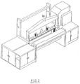
- Figur 2
- ist eine perspektivische, als Vorschlag dienende Wiedergabe einer Webmaschine, die mit einer Entstaubungsanlage gemäß der Erfindung ausgerüstet ist,
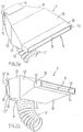
- Figur 3
- gibt als Seitenansicht die Anordnung der Blasöffnungen und der mit ihnen zusammenwirkenden Ansaugöffnung an der Webmaschine an.
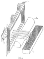
- Figur 4
- zeigt perspektivisch die Anordnung der Blasöffnungen und der mit ihnen zusammenwirkenden Ansaugöffnung an der Webmaschine.
- Die Figuren 5a und 5b
- sind zwei Zeichnungen einer Blasöffnung gemäß der Erfindung in Perspektive.
- Figure 1
- is a schematic diagram of a dedusting system according to the invention.
- Figure 2
- Fig. 3 is a perspective, suggested rendering of a weaving machine equipped with a dedusting system according to the invention,
- Figure 3
- shows a side view of the arrangement of the blowing openings and the suction opening interacting with them on the weaving machine.
- Figure 4
- shows in perspective the arrangement of the blowing openings and the suction opening interacting with them on the weaving machine.
- Figures 5a and 5b
- are two drawings of a blow opening according to the invention in perspective.
Eine bevorzugte Ausführungsform der Entstaubungsanlage und ihre gut festgelegte Anordnung hinsichtlich der Maschinen-Einzelteile kann jedoch exakt anhand einem Ausführungsbeispiels beschrieben werden. Im folgenden sei eine Webmaschine bekannter Konstruktion betrachtet, die mit einer Entstaubungsanlage gemaß der Erfindung ausgerüstet ist.A preferred embodiment of the dedusting system and its well-defined arrangement with regard to the individual machine parts can, however, be described exactly using an exemplary embodiment. The following is one Weaving machine of known construction considered, which is equipped with a dedusting system according to the invention.
Die Entstaubungsanlage gemäß der Erfindung enthält einen Aspirator (1) zum Ansaugen von Luft, der mit einer oder mehreren Öffnungen versehen ist, an denen die Luft in diesen Aspirator (1) hineingesogen wird, und eine oder mehrere Öffnungen, an denen die angesaugte Luft aus dem Aspirator (1) zurück geblasen wird, während an jenen genannten Öffnungen Leitungen angeschlossen werden können. Ferner ist in der Entstaubungsanlage gemäß der Erfindung eine Filtereinrichtung (2) vorgesehen, von der Staub oder anderer Abfall, der von der angesaugten Luft mitgeführt wurde, auf allgemein bekannte Art (siehe die belgische Patentschrift Nr. 08901086) aus dieser Luft derart herausgefiltert wird, daß einerseits der Staub oder andere Abfall in einem dafür vorgesehenen Auffangbehältnis (3) abgelagert wird und andererseits die gefilterte Luft zurück ausgeblasen wird. Diese Filtereinrichtung (2) ist folglich derart angeordnet, daß sich alle angesaugte Luft durch diese Filtereinrichtung (2) bewegen muß, ehe sie ausgeblasen wird, und kann entweder in den Aspirator (1) eingebaut oder durch eine Leitung, in der alle angesaugte Luft hindurchgeführt wird, mit dem Aspirator (1) verbunden sein, während eine andere an dieser Filtereinrichtung (2) angeschlossene Leitung die gefilterte Luft weiter durch die Anlage hindurch führt, damit sie schließlich ausgeblasen wird.The dedusting system according to the invention comprises an aspirator (1) for drawing in air, which is provided with one or more openings through which the air is drawn into this aspirator (1) and one or more openings through which the sucked-in air comes out the aspirator (1) is blown back, while lines can be connected to those openings. Furthermore, a filter device (2) is provided in the dedusting system according to the invention, from which dust or other waste carried along by the sucked-in air is filtered out of this air in a generally known manner (see Belgian Patent No. 08901086), that on the one hand the dust or other waste is deposited in a designated container (3) and on the other hand the filtered air is blown out. This filter device (2) is consequently arranged in such a way that all the air drawn in must move through this filter device (2) before it is blown out, and can either be installed in the aspirator (1) or through a line in which all the air drawn in passes will be connected to the aspirator (1), while another line connected to this filter device (2) leads the filtered air further through the system so that it is finally blown out.
Die Entstaubungsanlage gemäß der Erfindung enthält weiterhin noch eine Ansaugöffnung (4) mit einer rechteckigen Zufuhröffnung, die näherungsweise dieselbe Länge wie die Breite der Schäfte (5) besitzt. Diese Ansaugöffnung (4), deren Zufuhröffnung nach oben gerichtet ist, wird an der Rückseite der Schäfte (5) in der Nähe derart horizontal angeordnet, daß sie sichparallel zu den Schäften (5) und über deren gesamte Breite erstreckt. Diese Ansaugöffnung (4) ist mit Hilfe einer Leitung (4') an einer Ansaugöffnung des Aspirators (1) angeschlossen.The dedusting system according to the invention also contains a suction opening (4) with a rectangular feed opening which has approximately the same length as the width of the shafts (5). This suction opening (4), the supply opening of which is directed upwards, is arranged horizontally on the rear of the shafts (5) nearby in such a way that it extends parallel to the shafts (5) and over their entire width. This suction opening (4) is connected to a suction opening of the aspirator (1) with the aid of a line (4 ').
Die Entstaubungsanlage gemäß der Erfindung weist ferner noch eine Reihe Blasöffnungen (7) gemaß der Erfindung auf, die in einer horizontalen Reihe so dicht wie möglich beieinander unmittelbar vor den Schäften (5) angeordnet werden, wobei ihre Ausgangsöffnung (9) zu den Schäften (5) gerichtet ist und sich diese Reihe parallel zu den Schäften (5) und vorzugsweise über nahezu die vollständige Breite dieser Schäfte (5) erstreckt. Diese Blasöffnungen (7) sind mit Hilfe von Leitungen (7') an einer oder mehreren Blasöffnungen des Aspirators (1) angeschlossen.The dedusting system according to the invention also has a row of blowing openings (7) according to the invention, which are arranged in a horizontal row as close as possible to one another immediately in front of the stems (5), their outlet opening (9) to the stems (5 ) is directed and this row extends parallel to the shafts (5) and preferably over almost the full width of these shafts (5). These blow holes (7) are connected by means of lines (7 ') to one or more blowing openings of the aspirator (1).
Die Blasöffnungen (7) sind speziell für diese Anwendung entworfen und stellen einen Gegenstand der Erfindung dar (siehe Figuren 5a und 5b).The blow openings (7) are specially designed for this application and represent an object of the invention (see FIGS. 5a and 5b).
Die Blasöffnung (7) gemäß der Erfindung besteht aus einer kastenförmigen, aus ebenen Wänden zusammengesetzten Einheit, in der eine Eingangsöffnung (8) und eine Ausgangsöffnung (9) für die Luft vorgesehen sind, und die die anschließend erläuterte, in den Figuren 5a und 5b gezeigte Gestalt aufweist. An den vier Seiten der rechteckigen, ebenen Rückwand schließen sich eine ebene Deckwand (10) bzw. Grundwand (11) und zwei Seitenwände (12) an, wobei sich einerseits die Deckwand (10) und die Grundwand (11) und andrerseits die beiden Seitenwände (12) je zu zweit symmetrisch weiter voneinander entfernen. Diese vier Wände (10), (11) und (12) zeigen jeweils - im selben horizontalen Abstand von der Rückwand - einen geradlinigen Knick, hinter dem diese Wände ebene Abschnitte aufweisen, die jeweils zu zweit - einerseits die Deckwände (10) und die Grundwand (11), andererseits die beiden Seitenwände (12) - symmetrisch dichter zusammenkommen. In demselben Abstand von der Rückwand aus zeigen die vier Wände (10), (11) und (12) nochmals einen geradlinigen Knick, hinter dem diese Wände ebene Abschnitte besitzen, die zu zweit parallel verlaufen, um im selben horizontalen Abstand von der Rückwand aus an einem vorderen Rand zu endigen.The blowing opening (7) according to the invention consists of a box-shaped unit composed of flat walls, in which an inlet opening (8) and an outlet opening (9) for the air are provided, and which is subsequently explained in FIGS. 5a and 5b has the shape shown. A flat top wall (10) or base wall (11) and two side walls (12) adjoin the four sides of the rectangular, flat rear wall, the top wall (10) and the base wall (11) on the one hand and the two side walls on the other (12) symmetrically further apart from each other. These four walls (10), (11) and (12) each show - at the same horizontal distance from the rear wall - a straight bend, behind which these walls have flat sections, each for two - the top walls (10) and the Base wall (11), on the other hand the two side walls (12) - come closer together symmetrically. At the same distance from the rear wall, the four walls (10), (11) and (12) again show a straight bend, behind which these walls have flat sections which, in pairs, run in parallel by the same horizontal distance from the rear wall to end at a front edge.
Die obengenannten, an der Vorderseite endigenden Ränder der Wände der Blasöffnung (7) bilden dabei eine rechteckige Vorderseite von geringer Höhe und großer Breite (gleich der Breite der Blasöffnung (7)). Diese Vorderseite ist nicht abgeschlossen, sondern bildet die Ausgangsöffnung (9) der Blasöffnung (7).The abovementioned edges of the walls of the blowing opening (7), which end at the front, form a rectangular front of low height and great width (equal to the width of the blowing opening (7)). This front is not closed, but forms the exit opening (9) of the blowing opening (7).
An der Außenseite der ebenen Rückwand der Blasöffnung (7) sind parallel zueinander in der Breitenrichtung der Blasöffnung (7) und übereinander zwei vorspringende Randteile (13) und (14) befestigt, von denen der eine Randteil (13) festsitzt und der andere Randteil (14) höhenverstellbar ist und z. B. mit einer Schraube in der Blasöffnung (7) fest eingestellt werden kann. Die beiden Randteile haben einen in ihrer jeweiligen Richtung laufenden, umgebogenen Abschnitt. Für die Anordnung der verschiedenen Blasöffnungen (7) ist eine durchlaufende, gerade, mit Profil versehene Schiene (15) horizontal vor den Schäften (5) befestigt. Diese Schiene (15) besitzt oben entlang über ihre ganze Länge einen vertikal stehenden Flügel (15') von durchgehend derselben Höhe und unten entlang über die ganze Länge einen vertikalen, abwärts gerichteten Flügel (15''), der durchgehend dieselbe Höhe besitzt. Der vertikale Abstand zwischen den Rändern der beiden Flügel (15') und (15'') stimmt mit dem vertikalen Abstand zwischen den vorspringenden Randteilen (13) und (14) überein, damit die Blasöffnung (7) auf der Schiene (15) verschoben werden kann, wobei der umgebogene Abschnitt des oberen Randteiles (14) hinter dem oberen Rand des Flügels (15') einhakt und der umgebogene Abschnitt des unteren Randteiles (13) hinter dem unteren Rand des Flügels (15'') einhakt. Die Blasöffnung (7) kann an der Schiene (15) in die erwünschte Position verschoben werden. Mit Hilfe der festen Einstellung des oberen Randteiles (14) in einer bestimmten Höhe, um zu erreichen, daß die vorspringenden Randteile (13) und (14) der Blasöffnung (7) kräftig auf die Ränder der Flügel (15') und (15'') drücken, wird die Blasöffnung (7) unverschiebbar und stabil angeordnet.On the outside of the flat rear wall of the blowing opening (7) two projecting edge parts (13) and (14) are fastened parallel to one another in the width direction of the blowing opening (7) and one of which edge part (13) is stuck and the other edge part ( 14) is adjustable in height and z. B. can be fixed with a screw in the blow opening (7). The two edge parts have a bent section running in their respective direction. For the arrangement of the different blowing openings (7) a continuous, straight, profiled rail (15) is horizontally in front the shafts (5) attached. This rail (15) has a vertically standing wing (15 ') of the same height throughout its entire length and a vertical downward wing (15'') of the same height along the entire length. The vertical distance between the edges of the two wings (15 ') and (15'') corresponds to the vertical distance between the projecting edge parts (13) and (14) so that the blowing opening (7) is displaced on the rail (15) can be, wherein the bent portion of the upper edge part (14) hooks behind the upper edge of the wing (15 ') and the bent portion of the lower edge part (13) hooks behind the lower edge of the wing (15''). The blow opening (7) can be moved to the desired position on the rail (15). With the help of the fixed setting of the upper edge part (14) at a certain height in order to ensure that the projecting edge parts (13) and (14) of the blowing opening (7) firmly on the edges of the wings (15 ') and (15''), the blowing opening (7) is arranged so that it cannot move and is stable.
Die Eingangsöffnuug (8) befindet sich in der Grundwand (11) dicht neben der Rückseite der Blasöffnung (7). Längs dieser Öffnung (8) tritt die Luft in den von den Wänden (10), (11) und (12) umschlossenen Innenraum der Blasöffnung (7) ein. Innerhalb der Blasöffnung (7) strömt die Luft in Richtung der Ausgangsöffnung (9), wo sie die Blasöffnung (7) verläßt.The inlet opening (8) is located in the base wall (11) close to the rear of the blowing opening (7). Along this opening (8), the air enters the interior of the blowing opening (7) enclosed by the walls (10), (11) and (12). Inside the blowing opening (7), the air flows in the direction of the exit opening (9), where it leaves the blowing opening (7).
Die Form des von den Wänden (10), (11) und (12) umschlossenen Innenraumes erbringt nunmehr den erwünschten Vorteil der Erfindung. Diese Form ist derart bemessen, daß ein senkrechter Querschnitt durch die Blasöffnung (7) - parallel zu der Rückwand - in der Höhe der Zufuhröffnung (8) eine Fläche aufweist, die größer als der Abschnitt der Zufuhröffnung (8) ist. Die Luft, die aus der Zufuhröffnung (8) ausströmt, erhält somit plötzlich einen größeren Abschnitt - lotrecht zur Strömungsrichtung -.The shape of the interior enclosed by the walls (10), (11) and (12) now provides the desired advantage of the invention. This shape is dimensioned such that a vertical cross section through the blow opening (7) - parallel to the rear wall - has an area at the height of the feed opening (8) which is larger than the section of the feed opening (8). The air that flows out of the supply opening (8) suddenly receives a larger section - perpendicular to the flow direction.
Dieser Abschnitt vergrößert sich weiter, wenn man stets in der Richtung der Ausgangsöffnung (9) geht, (die Wände entfernen sich also voneinander), und man erreicht in der Höhe des hinteren Knickes in jenen Wänden ein Maximum. Während ihres Durchgangs durch die Blasöffnung (7) hat die Luft somit bis hierher einen allmählich zunehmenden Strömungsquerschnitt erhalten und folglich expandieren können. Die Strömungsgeschwindigkeit hat abgenommen, und der Druck, der bei der hohen Geschwindigkeit nicht sehr gleichmäßig über den ganzen Querschnitt verteilt war (dicht neben den Wänden ist er kleiner als in der Mitte) erhält eine gleichförmigere Verteilung.This section increases further if you always go in the direction of the exit opening (9) (the walls are separated from each other), and one reaches a maximum at the height of the rear bend in those walls. During its passage through the blow opening (7), the air has thus got a gradually increasing flow cross-section and has consequently been able to expand. The flow rate has decreased, and the pressure, which at the high speed is not very even was distributed over the entire cross-section (close to the walls it is smaller than in the middle) receives a more uniform distribution.
In dem zweiten Abschnitt der Blasöffnung (7) nähern sich die Wände (10), (11) und (12) einander, und der Querschnitt verringert sich von neuem, je dichter man an die Ausgangsöffnung (9) herankommt, um nahe bei der Ausgangsöffnung (9) ein Minimum zu erreichen, das von dort ab bis zu der Ausgangsöffnung (9) gleich bleibt.In the second section of the blow opening (7), the walls (10), (11) and (12) approach each other and the cross section decreases again the closer the exit opening (9) is to the near the exit opening (9) to achieve a minimum that remains the same from there to the exit opening (9).
Die Strömungsgeschwindigkeit der Luft wird somit allmählich bis zu der Blasgeschwindigkeit zunehmen. Der Druck nimmt allmählich zu und erhält die Möglichkeit, sich gleichförmig über den langen, schmalen Querschnitt zu verteilen.The air flow rate will thus gradually increase up to the blowing speed. The pressure increases gradually and is given the opportunity to be distributed evenly over the long, narrow cross-section.
Dies hat zur Folge, daß der Durchsatz an ausgeblasener Luft ungefähr über die vollständige Breite der Blasöffnung (9) identisch ist, so daß ein breiter Luftstrom zustandekommt. Dadurch daß verschiedene Blasöffnungen (7), dicht beieinander stehend, mit ihren Ausgangsöffnungen (9) längs einer geraden, sich verlängernden Linie angeordnet werden, erhält man während ihres Arbeitsablaufes über die vollständige Breite der Schäfte (5) eine schnell und gleichmäßig sich bewegende Luftschicht, in der der Staub mitgenommen wird. Man spricht von einer Luftgardine.The result of this is that the throughput of blown-out air is approximately the same over the entire width of the blowing opening (9), so that a wide air flow occurs. The fact that different blowing openings (7), standing closely together, with their outlet openings (9) arranged along a straight, lengthening line, results in a rapidly and uniformly moving air layer over the entire width of the shafts (5) during their work process, in which the dust is taken away. One speaks of an air curtain.
Die Ansaugöffnung (4) ist nunmehr derart angeordnet, daß die Luftgardine auf die Schäfte (5) gerichtet wird, Der Luftstrom nimmt die schwebenden Teilchen in ihrer Strömung mit und befördert sie zu der Ansaugöffnung (4). Nahezu alle Luft, die von den Blasöffnungen (7) hinausgeblasen wurde, wird gemeinsam mit dem mitgeführten Staub auf jene Weise durch die Ansaugöffnung (4) zurück aufgesogen. Diese Luft wird in der Filtereinrichtung (2) filtriert und von neuem von den Blasöffnungen (7) hinausgeblasen. Folglich beschreibt der größte Teil der Luft einen Kreislauf, was einen weiterhin besprochenen, hinzukommenden Vorteil der Erfindung bildet.The suction opening (4) is now arranged in such a way that the air curtain is directed onto the shafts (5). The air flow takes the floating particles with them in their flow and conveys them to the suction opening (4). Almost all air that was blown out of the blowing openings (7) is sucked back together with the dust carried in that way through the suction opening (4). This air is filtered in the filter device (2) and blown out again from the blowing openings (7). As a result, most of the air describes a cycle, which is a further discussed advantage of the invention.
Die hier dargestellte, bevorzugte Ausführungsform der Entstaubungsanlage gemäß der Erfindung wird ferner noch durch Ansaugöffnungen (16), (17) ergänzt, die in bezug auf die Webmaschine an zwei verschiedenen Orten angeordnet sind.The preferred embodiment of the dedusting system according to the invention shown here is further supplemented by suction openings (16), (17) which are arranged at two different locations with respect to the weaving machine.
Die Ansaugöffnung (16) ist in Form einer Kappe mit einer rechteckigen Zufuhröffnung ausgebildet, die, nach unten gerichtet, vor den Schäften (5) horizontal angeordnet und über eine Leitung (16') an einer Ansaugöffnung des Aspirators angeschlossen wird. Auf jene Weise wird während des Arbeitsablaufes der Webmaschine auch der aufsteigende Staub aus dem Raum vor den Schäften (5) entfernt, um über die Filtereinrichtung (2) schließlich in dem Auffangbehältnis (3) abgelagert zu werden.The suction opening (16) is designed in the form of a cap with a rectangular supply opening, which, directed downwards, is arranged horizontally in front of the shafts (5) and is connected to a suction opening of the aspirator via a line (16 '). In this way, the rising dust is also removed from the space in front of the shafts (5) during the work cycle of the weaving machine in order to be finally deposited in the collecting container (3) via the filter device (2).
Ferner wird in der Höhe der Orte, an denen die beiden Geweberänder abgeschnitten werden, immer wieder eine Ansaugöffnung (17) zum Aufsaugen dieser abgeschnittenen Ränder angeordnet. Dieser Abfall, der bis heute mechanisch zu einem gesonderten Abfallbehälter abgeführt wird, gelangt auf diese Weise ebenfalls in das gemeinsame Abfallbehältnis (3) der Webmaschine.Furthermore, a suction opening (17) for sucking up these cut edges is always arranged at the level at which the two fabric edges are cut off. This waste, which until today is mechanically discharged to a separate waste container, also ends up in the common waste container (3) of the weaving machine.
Eine Doppelstück-Webmaschine erzeugt außerdem eine erhebliche Menge Staub an dem Ort, wo Ober- und Untergewebe bei dem Durchschneiden der Polfäden voneinander getrennt werden. Dies geschieht mit einem schnell hin- und hergehenden Messer, das bei jeder Bewegung eine Reihe Polfäden durchschneidet. Der Staub, der hauptsächlich aus Fasern der durchschnittenen Fäden besteht, wird zu den Seitenrändern des Gewebes mitgenommen. Die Entstaubungsanlage gemäß der Erfindung kann an jenen Orten (an den Gegenseiten der Messerbahn) durch hinzugefügte Ansaugöffnungen (in den Figuren nicht dargestellt) ergänzt werden, die auch diesen Staub aufsaugen und über eine Leitung, die an einer Ansaugöffnung des Aspirators (1) angeschlossen wurde, in dem Auffangbehältnis (3) ablagern.A double piece weaving machine also creates a significant amount of dust where the top and bottom fabrics are separated when the pile threads are cut. This is done with a fast reciprocating knife that cuts a row of pile threads with every movement. The dust, which mainly consists of fibers from the cut threads, is taken to the side edges of the fabric. The dedusting system according to the invention can be supplemented at those locations (on the opposite sides of the knife path) by added suction openings (not shown in the figures) which also suck up this dust and via a line which was connected to a suction opening of the aspirator (1) , deposit in the collecting container (3).
Ein Vorteil der Entstaubungsanlage gemäß der Erfindung liegt vor allem in der Tatsache, daß während des Arbeitsvorganges der Webmaschine die Schäfte (5) durch die Erzeugung einer gerichteten Luftgardine entstaubt werden. Hierdurch tritt praktisch kein fliegender und frei umherwirbelnder Staub mehr auf, weil sich dieser Staub innerhalb der Luftgardine befindet und unmittelbar von einer Ansaugöffnung (4) abgesaugt wird. Die Schäfte (5) bleiben staubfrei. Die Widerstände von Staubsträhnen in dem Gewebe werden ausgeschaltet, und das Stillsetzen der Maschine zum Entstauben ist nicht mehr notwendig. Hinzu kommt noch, daß durch diese Anordnung der Blasöffnungen (7) und der Ansaugöffnung (4) und durch die Anordnung einer hinzugefügten Ansaugkappe (16), die vor den Schäften (5) die aufsteigenden Staubteilchen ansaugt, und durch eine eventuell hinzukommende Ansaugöffnung in der Höhe des Messers der größte Teil des von der Webmaschine entwickelten Staubes aufgesaugt wird und nicht mehr frei in der die Webmaschine umgebenden Luft umherschweben kann. Die Luft, die von den in jener Umgebung arbeitenden Menschen eingeatmet wird, enthält somit sehr wenig Staub, was die Arbeitsbedingungen stark verbessert und dem schädlichen Einfluß des Staubes auf die Gesundheit zuvorkommt.An advantage of the dedusting system according to the invention lies above all in the fact that the shafts (5) are dedusted by the production of a directed air curtain during the working process of the weaving machine. As a result, there is practically no flying dust whirling freely, because this dust is inside the air curtain and is sucked off directly from a suction opening (4). The shafts (5) remain dust-free. The resistances of strands of dust in the fabric are switched off and the machine for dust removal is no longer necessary. In addition, this arrangement of the blowing openings (7) and the suction opening (4) and by the arrangement of an added suction cap (16), which sucks the rising dust particles in front of the shafts (5), and by a possibly additional suction opening in the Amount of Knife the largest part of the dust developed by the loom is sucked up and can no longer float freely in the air surrounding the loom. The air inhaled by the people working in that environment therefore contains very little dust, which greatly improves working conditions and prevents the harmful effects of dust on health.
Ein zusätzlicher Vorteil der Entstaubungsanlage gemäß der Erfindung liegt in der Tatsache, daß keine Luft außerhalb des Arbeitsplatzes angesaugt wird. Die von den Blasöffnungen (7) hinausgeblasene Luft wird immer zum größten Teil durch die Ansaugöffnung (4) zurück angesaugt, filtriert und zu den Blasöffnungen zurückgeführt.An additional advantage of the dedusting system according to the invention lies in the fact that no air is sucked in outside the workplace. Most of the air blown out of the blowing openings (7) is sucked back through the suction opening (4), filtered and returned to the blowing openings.
Folglich ist eine große Menge der sich gerade bewegenden Luft stets dieselbe, wodurch die Temperatur und der Feuchtigkeitsgrad stets mit der Temperatur und dem Feuchtigkeitsgrad der Umgebungsluft des Arbeitsplatzes übereinstimmen.As a result, a large amount of the air currently moving is always the same, which means that the temperature and the degree of humidity always correspond to the temperature and the degree of humidity of the ambient air in the workplace.
Die Blasöffnungen (7) gemäß der Erfindung tragen in wesentlichem Maße zu einer guten Arbeitsweise der Entstaubungsanlage bei, indem sie eine breite, sich schnell bewegende Luftgardine bei einer gleichförmigen Geschwindigkeit in der gesamten Breite zu erzeugen ermöglichen.The blowing openings (7) according to the invention make a significant contribution to the good functioning of the dedusting system by making it possible to produce a wide, fast-moving air curtain at a uniform speed over the entire width.
Mit den bis heute bekannten Blasöffnungen wurde ein Luftstrom erzeugt, der in der Mitte eine größere Geschwindigkeit als an den Rändern aufweist und folglich bei derselben Breite der Blasöffnung eine weniger breite, wirksame Luftbewegung verursacht. Von den nahe beieinander angebrachten Blasöffnungen (7) gemäß der Erfindung wird eine Luftgardine erzeugt, in der die Luft gleichförmig über die Breite der Schäfte (5) verteilt wird. Dieser Effekt, der wesentlich für die Mitnahme von Staub ist, ohne daß dieser in allen Richtungen umherfliegen kann, ist mit den bestehenden Blasöffnungen nicht zu erreichen.With the blowing openings known to date, an air stream was generated which has a higher speed in the middle than at the edges and consequently causes less effective air movement with the same width of the blowing opening. An air curtain is produced from the blowing openings (7) according to the invention which are arranged close to one another, in which the air is distributed uniformly over the width of the shafts (5). This effect, which is essential for the transport of dust without it being able to fly around in all directions, cannot be achieved with the existing blowing openings.
Der erfindungsgemäß erzeugte Luftvorhang verläuft am besten auf kürzestem Wege, also in horizontaler Ebene, durch die Öffnungen der Schäfte. Der Luftstrom wird dann nach Überstreichen eines querverlaufenden, zur tieferliegenden Ansaugöffnung 4 hin abgerundeten Füllkörpers 20 vom Ansaugstrom erfaßt und in die vertikal nach oben gerichteten Ansaugöffnungen 4 eingesogen. Würde man dagegen, wie ansonsten üblich, den horizontalen Luftstrom unmittelbar in die sich auf den Luftstrom zu öffnenden Ansaugöffnung einer dementsprechend im Luftstrom plazierten Ansaugkammer richten, ergäben sich ernsthafte Einbauraumprobleme in eben diesem Bereich. Erfindungsgemäß kann die Absaugeinrichtung in einen weiter untenliegenden und damit weniger kritischen Bereich verlegt werden. Auch ergibt sich eine günstige Strömungsführung, zumal der in horizontaler Ebene liegende Ansaugquerschnitt ohne weiteres vorteilhaft groß gewählt werden kann.The air curtain produced according to the invention runs best by the shortest route, that is to say in a horizontal plane, through the openings of the shafts. After sweeping over a
Einige wichtige Gesichtspunkte werden im folgenden wiedergegeben:
Die Erfindung betrifft eine Anlage zum selbsttätigen Entstauben einer Maschine während ihrer Arbeit, die aus einer Ansaugeinrichtung (1), einer Filtereinrichtung (2) und einer Blaseinrichtung (1) besteht, während an der Blaseinrichtung (1) angeschlossene Blasöffnungen (7) derart angeordnet werden, daß der austretende Luftstrom auf möglichst gut zugängliche und sich bewegende, den Staub hervorrufende Einzelteile (5) jener Maschine gerichtet ist, und daß dieser Luftstrom die schwebenden Staubteilchen zu einer an der Ansaugeinrichtung (1) angeschlossenen Ansaugöffnung (4) mitnimmt und befördert, während die angesaugte Luft mit Staub zu einer Filtereinrichtung (2) geführt und die saubere Luft eventuell über die Blasöffnungen (7) zurück in den Arbeitsraum geblasen wird. Eine Blasöffnung (7) verfügt über eine beschränkte Zufuhröffnung und einen breiteren Innenraum, der in Strömungsrichtung der Luft zuerst einen allmählich zunehmenden Querschnitt besitzt, dem ein allmählich abnehmender Querschnitt folgt, um zu einer spaltförmigen Ausgangsöffnung (9) zu gelangen, wodurch der erzeugte Luftstrom, gleichmäßig verteilt, über die Ausgangsöffnung (9) die Blasöffnung (7) verläßt.Some important points of view are given below:
The invention relates to a system for the automatic dedusting of a machine during its work, comprising a suction device (1), a filter device (2) and a blowing device (1), while blowing openings (7) connected to the blowing device (1) are arranged in this way that the escaping air flow is directed towards the most accessible and moving dust-producing parts (5) of that machine, and that this air flow takes the floating dust particles to a suction opening (4) connected to the suction device (1) and conveys them while the sucked-in air with dust is led to a filter device (2) and the clean air is possibly blown back into the work area via the blower openings (7). A blowing opening (7) has a restricted supply opening and a wider interior, which first has a gradually increasing cross-section in the direction of flow of the air, which is followed by a gradually decreasing cross-section in order to reach a gap-shaped outlet opening (9), as a result of which the air flow generated, evenly distributed, leaves the blow opening (7) via the outlet opening (9).
Claims (20)
Applications Claiming Priority (2)
| Application Number | Priority Date | Filing Date | Title |
|---|---|---|---|
| BE9100880 | 1991-09-20 | ||
| BE9100880A BE1005398A5 (en) | 1991-09-20 | 1991-09-20 | Dedusting FOR MACHINES. |
Publications (2)
| Publication Number | Publication Date |
|---|---|
| EP0535501A2 true EP0535501A2 (en) | 1993-04-07 |
| EP0535501A3 EP0535501A3 (en) | 1994-12-28 |
Family
ID=3885720
Family Applications (1)
| Application Number | Title | Priority Date | Filing Date |
|---|---|---|---|
| EP92116141A Withdrawn EP0535501A3 (en) | 1991-09-20 | 1992-09-21 | Dust removal plant for machines |
Country Status (4)
| Country | Link |
|---|---|
| EP (1) | EP0535501A3 (en) |
| JP (1) | JPH0866667A (en) |
| KR (1) | KR930005658A (en) |
| BE (1) | BE1005398A5 (en) |
Cited By (8)
| Publication number | Priority date | Publication date | Assignee | Title |
|---|---|---|---|---|
| US5524676A (en) * | 1994-04-07 | 1996-06-11 | Lindauer Dornier Gesellschaft Mbh | Weaving loom with articulated suction apparatus for reducing deposition of fly lint and dust |
| EP0876855A3 (en) * | 1997-05-09 | 2000-03-22 | Focke & Co. (GmbH & Co.) | Method and installation for cleaning packaging machines |
| EP2280103A1 (en) * | 2009-07-29 | 2011-02-02 | Firma Sohler Neuenhauser GmbH & Co. KG | Cleaning device for looms |
| CN107552528A (en) * | 2017-10-12 | 2018-01-09 | 浙江百事德办公设备有限公司 | One kind printing, duplicate all-in-one dust arrester |
| CN109530334A (en) * | 2018-12-27 | 2019-03-29 | 天津翰克科技有限公司 | A kind of slit dust pelletizing system |
| CN111793958A (en) * | 2020-07-22 | 2020-10-20 | 卢兰 | Cloth low noise dust collecting equipment |
| CN112691477A (en) * | 2020-12-07 | 2021-04-23 | 辽宁工程技术大学 | Air curtain and cloth bag combined type dust removal device suitable for transfer system |
| CN116456214A (en) * | 2023-06-16 | 2023-07-18 | 深圳市创智天成科技有限公司 | Dustproof device for router |
Families Citing this family (1)
| Publication number | Priority date | Publication date | Assignee | Title |
|---|---|---|---|---|
| CN112501756B (en) * | 2020-10-05 | 2022-07-05 | 绍兴义鼎纺织有限公司 | Spinning rack with dust collecting function |
Citations (6)
| Publication number | Priority date | Publication date | Assignee | Title |
|---|---|---|---|---|
| US3311135A (en) * | 1965-06-24 | 1967-03-28 | Grinnell Corp | Lint collecting enclosure |
| CH584302A5 (en) * | 1974-12-10 | 1977-01-31 | Mueller Jakob Forschungs Und F | Pneumatic cleaning device for tape-weaving machine - formed by blower pipe located below shed and a suction hood disposed above shed over pipe |
| GB2021161A (en) * | 1978-05-17 | 1979-11-28 | Rossville Mills Inc | Shuttleless looms |
| US4676277A (en) * | 1986-04-18 | 1987-06-30 | Abington, Inc. | Vacuum cleaning system for the automatic insertion area of a weaving machine |
| DE3710367A1 (en) * | 1987-03-28 | 1988-10-13 | Klaus Brankamp System Prozessa | Device for de-oiling bulk parts |
| EP0291485A1 (en) * | 1987-05-12 | 1988-11-17 | Picanol N.V. | Device for removing waste products from textile machines |
-
1991
- 1991-09-20 BE BE9100880A patent/BE1005398A5/en not_active IP Right Cessation
-
1992
- 1992-09-21 EP EP92116141A patent/EP0535501A3/en not_active Withdrawn
- 1992-09-21 KR KR1019920017150A patent/KR930005658A/en not_active Application Discontinuation
- 1992-09-21 JP JP4251691A patent/JPH0866667A/en active Pending
Patent Citations (6)
| Publication number | Priority date | Publication date | Assignee | Title |
|---|---|---|---|---|
| US3311135A (en) * | 1965-06-24 | 1967-03-28 | Grinnell Corp | Lint collecting enclosure |
| CH584302A5 (en) * | 1974-12-10 | 1977-01-31 | Mueller Jakob Forschungs Und F | Pneumatic cleaning device for tape-weaving machine - formed by blower pipe located below shed and a suction hood disposed above shed over pipe |
| GB2021161A (en) * | 1978-05-17 | 1979-11-28 | Rossville Mills Inc | Shuttleless looms |
| US4676277A (en) * | 1986-04-18 | 1987-06-30 | Abington, Inc. | Vacuum cleaning system for the automatic insertion area of a weaving machine |
| DE3710367A1 (en) * | 1987-03-28 | 1988-10-13 | Klaus Brankamp System Prozessa | Device for de-oiling bulk parts |
| EP0291485A1 (en) * | 1987-05-12 | 1988-11-17 | Picanol N.V. | Device for removing waste products from textile machines |
Cited By (11)
| Publication number | Priority date | Publication date | Assignee | Title |
|---|---|---|---|---|
| US5524676A (en) * | 1994-04-07 | 1996-06-11 | Lindauer Dornier Gesellschaft Mbh | Weaving loom with articulated suction apparatus for reducing deposition of fly lint and dust |
| EP0876855A3 (en) * | 1997-05-09 | 2000-03-22 | Focke & Co. (GmbH & Co.) | Method and installation for cleaning packaging machines |
| EP2280103A1 (en) * | 2009-07-29 | 2011-02-02 | Firma Sohler Neuenhauser GmbH & Co. KG | Cleaning device for looms |
| CN101988231A (en) * | 2009-07-29 | 2011-03-23 | 佐勒-诺伊恩豪泽尔有限公司和两合公司 | Cleaning device for looms |
| CN107552528A (en) * | 2017-10-12 | 2018-01-09 | 浙江百事德办公设备有限公司 | One kind printing, duplicate all-in-one dust arrester |
| CN109530334A (en) * | 2018-12-27 | 2019-03-29 | 天津翰克科技有限公司 | A kind of slit dust pelletizing system |
| CN111793958A (en) * | 2020-07-22 | 2020-10-20 | 卢兰 | Cloth low noise dust collecting equipment |
| CN111793958B (en) * | 2020-07-22 | 2022-09-23 | 北京蔚蓝君成科技产业发展有限公司 | Cloth low noise dust collecting equipment |
| CN112691477A (en) * | 2020-12-07 | 2021-04-23 | 辽宁工程技术大学 | Air curtain and cloth bag combined type dust removal device suitable for transfer system |
| CN116456214A (en) * | 2023-06-16 | 2023-07-18 | 深圳市创智天成科技有限公司 | Dustproof device for router |
| CN116456214B (en) * | 2023-06-16 | 2023-08-25 | 深圳市创智天成科技有限公司 | Dustproof device for router |
Also Published As
| Publication number | Publication date |
|---|---|
| KR930005658A (en) | 1993-04-20 |
| BE1005398A5 (en) | 1993-07-13 |
| JPH0866667A (en) | 1996-03-12 |
| EP0535501A3 (en) | 1994-12-28 |
Similar Documents
| Publication | Publication Date | Title |
|---|---|---|
| DE1510381C3 (en) | Device for separating fluff extracted from spinning machines, in particular cards | |
| DE1275264B (en) | Device for cleaning textile machines arranged in a row | |
| EP0291707A2 (en) | Sandblast cabinet | |
| DE1535894C3 (en) | Device for cleaning the top of looms | |
| DE2430347A1 (en) | AIR PURIFICATION ARRANGEMENT AND PROCEDURE | |
| EP0535501A2 (en) | Dust removal plant for machines | |
| DE2812743C2 (en) | ||
| DE1510316A1 (en) | Device on textile machines, especially in the area of the intake sections of spinning machines, for the pneumatic detection and removal of contaminants | |
| WO1982003114A1 (en) | Air conditionned room and method for using same | |
| EP1340844B1 (en) | Meltblown apparatus | |
| DE3419028C2 (en) | ||
| DE1252870C2 (en) | DRIVING CLEANING DEVICE FOR THE REMOVAL OF THE GASER FLIGHT, etc. OF MACHINE PARTS AND THE FLOOR IN TEXTILE MACHINE SHELVES | |
| DE1786108B2 (en) | Device for the continuous dedusting of material webs | |
| DE3338980C2 (en) | ||
| DE3718257A1 (en) | METHOD AND DEVICE FOR CLEANING (FLUSH) SCREENS OF A DEVICE FOR SMOOTHING CLOTHES | |
| CH676254A5 (en) | ||
| DE2339880A1 (en) | PNEUMATIC CLEANING SYSTEM OF THE DRAWING SYSTEMS IN SPINNING AND SPINNING MACHINES | |
| EP0125620A1 (en) | Air filter system | |
| DE3830991A1 (en) | Filter apparatus and method for the operation thereof | |
| DE1710436B2 (en) | MOBILE CLEANING DEVICE FOR TEXTILE MACHINERY | |
| DE3417101A1 (en) | FLUSH FILTER DEVICE OF A CONVECTION DRYING AND / OR FIXING MACHINE | |
| EP3668631A1 (en) | Air purification plant with integrated filter cleaning device | |
| DE102005008210B4 (en) | Method and device for screening a mixture of materials | |
| CH627798A5 (en) | PNEUMATIC CLEANING DEVICE ON THE INLET TABLE OF A SPINNING MACHINE. | |
| DE1510321C3 (en) | Device on cards for the pneumatic removal of contaminants |
Legal Events
| Date | Code | Title | Description |
|---|---|---|---|
| PUAI | Public reference made under article 153(3) epc to a published international application that has entered the european phase |
Free format text: ORIGINAL CODE: 0009012 |
|
| AK | Designated contracting states |
Kind code of ref document: A2 Designated state(s): CH DE ES FR GB IT LI NL |
|
| RAP1 | Party data changed (applicant data changed or rights of an application transferred) |
Owner name: WULBRECHT, HENDRIK Owner name: N.V. MICHEL VAN DE WIELE |
|
| PUAL | Search report despatched |
Free format text: ORIGINAL CODE: 0009013 |
|
| AK | Designated contracting states |
Kind code of ref document: A3 Designated state(s): CH DE ES FR GB IT LI NL |
|
| STAA | Information on the status of an ep patent application or granted ep patent |
Free format text: STATUS: THE APPLICATION IS DEEMED TO BE WITHDRAWN |
|
| 18D | Application deemed to be withdrawn |
Effective date: 19950401 |