EP0534987B1 - Pad retaining system in disc brakes for road vehicles, especially utility vehicles - Google Patents
Pad retaining system in disc brakes for road vehicles, especially utility vehicles Download PDFInfo
- Publication number
- EP0534987B1 EP0534987B1 EP91908950A EP91908950A EP0534987B1 EP 0534987 B1 EP0534987 B1 EP 0534987B1 EP 91908950 A EP91908950 A EP 91908950A EP 91908950 A EP91908950 A EP 91908950A EP 0534987 B1 EP0534987 B1 EP 0534987B1
- Authority
- EP
- European Patent Office
- Prior art keywords
- leaf spring
- lining
- pressure distribution
- distribution plate
- outer edge
- Prior art date
- Legal status (The legal status is an assumption and is not a legal conclusion. Google has not performed a legal analysis and makes no representation as to the accuracy of the status listed.)
- Expired - Lifetime
Links
- 230000033001 locomotion Effects 0.000 claims description 4
- 230000000149 penetrating effect Effects 0.000 claims 1
- 244000145845 chattering Species 0.000 abstract 1
- 230000001133 acceleration Effects 0.000 description 3
- 239000000969 carrier Substances 0.000 description 3
- 238000004519 manufacturing process Methods 0.000 description 3
- 208000027418 Wounds and injury Diseases 0.000 description 2
- 238000010276 construction Methods 0.000 description 2
- 230000006378 damage Effects 0.000 description 2
- 239000002360 explosive Substances 0.000 description 2
- 208000014674 injury Diseases 0.000 description 2
- 238000003780 insertion Methods 0.000 description 2
- 230000037431 insertion Effects 0.000 description 2
- 229910000639 Spring steel Inorganic materials 0.000 description 1
- 230000015572 biosynthetic process Effects 0.000 description 1
- 230000000295 complement effect Effects 0.000 description 1
- 238000011161 development Methods 0.000 description 1
- 230000018109 developmental process Effects 0.000 description 1
- 238000009434 installation Methods 0.000 description 1
- 230000009191 jumping Effects 0.000 description 1
- 230000014759 maintenance of location Effects 0.000 description 1
- 239000000203 mixture Substances 0.000 description 1
- 238000000926 separation method Methods 0.000 description 1
- 230000007704 transition Effects 0.000 description 1
Images
Classifications
-
- F—MECHANICAL ENGINEERING; LIGHTING; HEATING; WEAPONS; BLASTING
- F16—ENGINEERING ELEMENTS AND UNITS; GENERAL MEASURES FOR PRODUCING AND MAINTAINING EFFECTIVE FUNCTIONING OF MACHINES OR INSTALLATIONS; THERMAL INSULATION IN GENERAL
- F16D—COUPLINGS FOR TRANSMITTING ROTATION; CLUTCHES; BRAKES
- F16D65/00—Parts or details
- F16D65/78—Features relating to cooling
- F16D65/84—Features relating to cooling for disc brakes
-
- F—MECHANICAL ENGINEERING; LIGHTING; HEATING; WEAPONS; BLASTING
- F16—ENGINEERING ELEMENTS AND UNITS; GENERAL MEASURES FOR PRODUCING AND MAINTAINING EFFECTIVE FUNCTIONING OF MACHINES OR INSTALLATIONS; THERMAL INSULATION IN GENERAL
- F16D—COUPLINGS FOR TRANSMITTING ROTATION; CLUTCHES; BRAKES
- F16D65/00—Parts or details
- F16D65/02—Braking members; Mounting thereof
- F16D65/04—Bands, shoes or pads; Pivots or supporting members therefor
- F16D65/092—Bands, shoes or pads; Pivots or supporting members therefor for axially-engaging brakes, e.g. disc brakes
- F16D65/095—Pivots or supporting members therefor
- F16D65/097—Resilient means interposed between pads and supporting members or other brake parts
- F16D65/0973—Resilient means interposed between pads and supporting members or other brake parts not subjected to brake forces
- F16D65/0974—Resilient means interposed between pads and supporting members or other brake parts not subjected to brake forces acting on or in the vicinity of the pad rim in a direction substantially transverse to the brake disc axis
- F16D65/0977—Springs made from sheet metal
- F16D65/0978—Springs made from sheet metal acting on one pad only
Definitions
- the invention relates to a covering holder according to the preamble of claim 1.
- Pin connections have the disadvantage that when the pin is driven out, an explosion-like relaxation of the strongly pre-tensioned pad retaining spring can occur, which in the worst case results in personal injury.
- this problem can be avoided in principle by a suitable choice of the screw-in length, which provides for engagement of the screw in the nut thread up to the relaxed state of the spring, but due to the operating conditions of the disc brake (heat, cold, dirt, moisture) The screw cannot corrode completely. This can lead to the screw head being sheared off during the attempt to loosen and thus the same problem of explosion-like relaxation occurs as exists with pin connections in the aforementioned manner.
- Disc brakes for commercial vehicles with large-sized brake pads have pressure distributing plates for distributing the application forces, which can be inserted into the brake caliper shafts in a manner comparable to the pad carrier plates and are secured in the same way by means of retaining springs against rattling and deflection of the guide walls.
- pressure distributor plates of this type which are generally arranged between the mechanical application element and the lining carrier plate, problems of the type mentioned above can occur if the retaining bracket acting both on the lining carrier and on the pressure distributor plate is removed.
- a pad holder according to the preamble of claim 1 is known from EP-A-0 248 385.
- This known lining holder has at least one lining shaft provided on a brake caliper or a brake housing, into which a lining carrier carrying a friction lining and possibly a pressure distributor plate can be inserted, a leaf spring acting on the outer edges of the lining carrier and possibly the pressure distributor plate, which saddles - or supported on the housing side on a detachable hold-down element.
- a holding tab is also formed in each case, which has a semicircular recess in which a correspondingly complementary or semi-arched end of the leaf spring engages.
- the invention is therefore based on the object of developing a covering holder according to the preamble of claim 1 in such a way that, despite inexpensive manufacture, a sudden expansion of the leaf spring can be reliably prevented during dismantling.
- both the lining carrier and the leaf spring is consequently very simple and yet of absolutely safe mode of operation, the leaf spring in the tensioned state with its recesses being able to be guided over the holding tabs in such a way that the holding tabs with subsequent complete or partial relaxation of the leaf spring have their recesses enforce and the leaf spring is held captive.
- An advantage of the captive mounting of the leaf spring on the lining carrier or on the pressure distribution plate is also that pre-assembly of the leaf spring e.g. can be done in the workshop, i.e. it is no longer necessary to insert the leaf spring within a confined space.
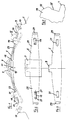
- Fig. 1 of the drawing is shown in a simplified side view, the generally upper end of a lining carrier 1 in the installed position, which e.g. is designed as a carrier plate and can be inserted into the lining shaft of a disc brake with the friction lining (not shown) attached to it. Eyes 3 can be provided on the lining carrier, by means of which eyes the lining carrier can be pulled out of the lining shaft.
- the (not shown) friction lining is in a manner known per se opposite a (not shown) brake disk, tensioning elements also being effective in a known manner in order to press the friction linings preferably on both sides of the brake disk.
- the lining carriers or pressure distribution plates are each held after insertion into their lining shaft with the aid of a leaf spring 5, which itself is transversely to the longitudinal axis of the leaf spring by a spring acting from the top on the leaf spring extending bracket is secured.
- the retaining bracket 7 shown in FIG. 1 in an end view and in FIG. 2 in partial top view can be attached at one end to an abutment (not shown) or the like holding element of the brake caliper housing and can preferably be braced against the brake caliper housing with a screw at the opposite end. in such a way that a force directed downward as shown in FIG. 1 is exerted on the leaf spring 5 and accordingly on the lining carrier 1 with the aid of the holding bracket 7.
- the leaf spring 5 is provided with a lateral projection 9, against which the bracket comes to rest; the leaf spring 5 can also be designed in cooperation with the retaining bracket, ie in the central region, in another way to absorb the clamping forces of the retaining bracket.
- the leaf spring 5 is in turn clamped against the spring force by the retaining bracket 7 against the spring force for the purpose of resiliently bracing the lining carrier 1, which is why the leaf spring 5 in the installed state has a more flattened configuration than the relaxed state, as can be seen from FIG.
- the relaxed state of the leaf spring is dashed, i.e. the state before assembly of the leaf spring on the lining carrier, shown, while the installation state of the leaf spring 5 on the top of the lining carrier 1 is shown with tension by the bracket 7 with solid lines.
- holding tabs 19 extend from the outer edge 11 of the lining carrier, into which the two ends of the leaf spring can be hung.
- the leaf spring has recesses 21, through which the retaining tabs 19 can be passed in the tensioned state of the leaf spring.
- the distance of the Holding tabs 19 on both sides of the central axis and the distance between the recesses 21 on both sides of the central part 15 of the leaf spring is chosen so that the side legs 23 of the leaf spring 5 can only be guided and hooked over the holding tabs 19 in their tensioned state.
- the leaf spring can be fastened to the outer edge 11 of the lining carrier with the lining carrier detached from the brake caliper or it is carried out directly after the lining carrier has been inserted into the lining shaft, in any case the fastening takes place before the subsequent positioning and screwing of the retaining bracket 7, which according to it Attachment exerts a downward force on the leaf spring 5 positioned on the lining carrier. If the disc brake is subjected to strong impacts, ie very high accelerations, when the vehicle is in motion, then the leaf spring 5 counteracts outward movements of the lining carrier; This prevents the linings from rattling or knocking out of the guide surfaces in the lining shaft.
- the retaining tabs 19 have undercuts 25 on the outside, ie in a position facing the eyes 3.
- the two retaining tabs 19 reach through the windows or recesses 21 in the two legs 23 in the manner shown in FIG. 1, ie the leaf spring 5 is captive the retaining tabs 19 are held, the two outer edges of the recesses 21 being without contact with the retaining tabs.
- the leaf spring 5 can be removed from the retaining tabs 19 if the retaining bracket 7 is previously released from its holding position by loosening its screw connection (not shown) on the brake caliper.
- FIG. 4 and also according to FIG. 1 show that the retaining tabs preferably have bevels 27 in the region of the outer edge; these bevels make it easier to mount the leaf spring, since it can be pressed resiliently over the bevels in order to assume the position on the brake disk carrier shown in solid lines in FIG.
- the leaf spring 5 can be rounded at its two ends 29 in an upward direction such that the ends abut at the transition to the tabs 17, as illustrated in FIG. 1.
- the invention is not limited to such an embodiment of the leaf spring, ie, the principle underlying the invention of holding the leaf spring on the lining carrier, even with a different design of the leaf spring ends and with a different shape of the lining carrier provided, for pulling out of the lining shaft serving eyelets realized.
- Leaf springs of the type described are preferably made of spring steel of known composition.
- the manufacture of such leaf springs is very easy to implement, ie they can be manufactured with the simplest tools. In the same way, it is very simple from a manufacturing point of view to provide retaining tabs 19 of the prescribed construction and mode of operation on the lining carrier 1.
Landscapes
- Engineering & Computer Science (AREA)
- General Engineering & Computer Science (AREA)
- Mechanical Engineering (AREA)
- Braking Arrangements (AREA)
Abstract
Description
Die Erfindung betrifft eine Belaghalterung nach dem Gattungsbegriff des Patentanspruchs 1.The invention relates to a covering holder according to the preamble of claim 1.
Bei Scheibenbremsen, insbesondere Teilbelagscheibenbremsen bekannter Konstruktion, welche sowohl in Personenkraftwagen als auch in Nutzfahrzeugen verwendbar sind, werden in Belagschächten einführbare, Reibbeläge tragende Belagträger bzw. Tragplatten verwendet, welche zum Zwecke der Abbremsung einer Bremsscheibe durch Zuspannmittel an diese angepreßt werden. Beim Befahren von Bodenunebenheiten treten an Rad -und Fahrzeugachse und damit an der mit der Fahrzeugachse starr verbundenen Bremse sehr hohe Beschleunigungen auf, deren Größenordnung mit ca 20 g angesetzt wird. Die Belagträger sind derartigen Beschleunigungen ausgesetzt und besitzen die Neigung, innerhalb der Belagschächte und ihrer Führungen mit hoher Wucht aufzuschlagen, vorzugsweise senkrecht zur Bodenebene, so daß diese Kräfte in vollem Unfang auf die Bauteile der Scheibenbremse einwirken können.In the case of disc brakes, in particular partial lining disc brakes of known construction, which can be used both in passenger cars and in commercial vehicles, insertable, friction lining-bearing lining carriers or carrier plates are used in lining shafts, which are pressed onto the brake disk by application means for the purpose of braking it. When driving on uneven ground, very high accelerations occur on the wheel and vehicle axles and thus on the brakes rigidly connected to the vehicle axle, the magnitude of which is set at approx. The lining carriers are exposed to such accelerations and have the tendency to hit the lining shafts and their guides with high force, preferably perpendicular to the ground plane, so that these forces can act in full on the components of the disc brake.
Zur Vermeidung der Klapperns der Beläge bzw. des Ausschlagens der Führungsflächen in den Belagschächten ist es bekannt, an der Außenkante der Belagträger Blattfedern zur Wirkung kommen zu lassen, welche den Bremsbelag in seiner Gesamtheit federnd verspannen. Um einen schnellen Belagwechsel mit geringstmöglichem Aufwand durchführen zu können, ist ein vom Bremssattelgehäuse getragener, z.B. an diesem verschraubbarer Haltebügel vorgesehen, welcher auf die Blattfedern einwirkt und diese unter Vorspannung an die Außenkante des Belagträgers anpreßt. Haltebügel dieser Art werden unter anderem mit Schraubverbindungen oder mit einfachen Stiftverbindungen am Bremssattelgehäuse fixiert. Stiftverbindungen haben dabei den Nachteil, daß es beim Austreiben des Stiftes zu einer explosionsartigen Entspannung der stark vorgespannten Belaghaltefeder kommen kann, was schlimmstenfalls Personenschaden zur Folge hat. Bei Schraubverbindungen kann dieses Problem durch geeignete Wahl der Einschraublänge, die einen Eingriff der Schraube im Muttergewinde bis hin zum entspannten Zustand der Feder vorsieht, zwar prinzipiell vermieden werden, jedoch ist auf Grund der Betriebsbedingungen der Scheibenbremse (Hitze, Kälte, Schmutz, Feuchtigkeit) ein Festkorrodieren der Schraube nicht vollständig auszuschließen. Dies kann dazu führen, daß der Schraubenkopf beim Löseversuch abgeschert wird und damit das gleiche Problem der explosionsartigen Entspannung auftritt, wie es bei Stiftverbindungen in vorgenannter Weise existiert.In order to avoid the rattling of the linings or the deflection of the guide surfaces in the lining shafts, it is known to allow leaf springs to act on the outer edge of the lining carrier which resiliently brace the brake lining in its entirety. Around To be able to carry out a quick lining change with the least possible effort, there is a holding bracket which is supported by the brake caliper housing and can be screwed to it, for example, which acts on the leaf springs and presses them against the outer edge of the lining carrier under pretension. Retaining brackets of this type are fixed to the caliper housing using screw connections or simple pin connections. Pin connections have the disadvantage that when the pin is driven out, an explosion-like relaxation of the strongly pre-tensioned pad retaining spring can occur, which in the worst case results in personal injury. In the case of screw connections, this problem can be avoided in principle by a suitable choice of the screw-in length, which provides for engagement of the screw in the nut thread up to the relaxed state of the spring, but due to the operating conditions of the disc brake (heat, cold, dirt, moisture) The screw cannot corrode completely. This can lead to the screw head being sheared off during the attempt to loosen and thus the same problem of explosion-like relaxation occurs as exists with pin connections in the aforementioned manner.
Scheibenbremsen für Nutzfahrzeuge mit großflächig dimensionierten Bremsbelägen weisen zur Verteilung der Zuspannkräfte dienende Druckverteilerplatten auf, welche in einer den Belagträgerplatten vergleichbaren Weise in Schächte des Bremssattels einführbar sind und in gleicher Weise mittels Haltefedern gegenüber Klappern und Ausschlagen der Führungwände abgesichert sind. Auch bei derartigen Druckverteilerplatten, welche im allgemeinen zwischen dem mechanischen Zuspannelement und der Belagträgerplatte angeordnet sind, können Probleme der vorstehend genannten Art auftreten, wenn der sowohl auf den Belagträger als auch auf die Druckverteilerplatte einwirkende Haltebügel demontiert wird.Disc brakes for commercial vehicles with large-sized brake pads have pressure distributing plates for distributing the application forces, which can be inserted into the brake caliper shafts in a manner comparable to the pad carrier plates and are secured in the same way by means of retaining springs against rattling and deflection of the guide walls. Even with pressure distributor plates of this type, which are generally arranged between the mechanical application element and the lining carrier plate, problems of the type mentioned above can occur if the retaining bracket acting both on the lining carrier and on the pressure distributor plate is removed.
Eine Belaghalterung gemäß dem Oberbegriff des Anspruchs 1 ist aus der EP-A-0 248 385 bekannt. Diese bekannte Belaghalterung weist mindestens einen an einem Bremssattel bzw. einem Bremsgehäuse vorgesehenen Belagschacht auf, in den ein einen Reibbelag tragender Belagträger und ggf. eine Druckverteilerplatte einführbar ist, wobei auf die Außenkanten des Belagträgers und ggf. der Druckverteilerplatte eine Blattfeder einwirkt, die sich sattel- bzw. gehäuseseitig an einem lösbaren Niederhalteelement abstützt. Auf beiden Seiten des Belagträgers bzw. der Druckverteilerplatte ist ferner jeweils eine Haltelasche ausgebildet, die eine halbrunde Ausnehmung aufweist, in die ein entsprechend komplementär bzw. als Halbbogen ausgebildetes Ende der Blattfeder eingreift. Hierdurch wird einerseits ein leichtes Einführen der Blattfeder erreicht und andererseits sichergestellt, daß sich die Blattfeder bei der Demontage nicht ohne weiteres löst.A pad holder according to the preamble of claim 1 is known from EP-A-0 248 385. This known lining holder has at least one lining shaft provided on a brake caliper or a brake housing, into which a lining carrier carrying a friction lining and possibly a pressure distributor plate can be inserted, a leaf spring acting on the outer edges of the lining carrier and possibly the pressure distributor plate, which saddles - or supported on the housing side on a detachable hold-down element. On both sides of the lining carrier or the pressure distribution plate, a holding tab is also formed in each case, which has a semicircular recess in which a correspondingly complementary or semi-arched end of the leaf spring engages. In this way, on the one hand, an easy insertion of the leaf spring is achieved and, on the other hand, it is ensured that the leaf spring does not easily come loose during disassembly.
Die genannte Ausbildung der Haltelasche hat jedoch den Nachteil, daß das eingangs genannte explosionsartige Entspannen insofern nicht unter allen Umständen verhindert werden kann, als bereits ein geringfügiges Manipulieren an der Blattfeder dazu führt, daß diese ihren Sitz vorzeitig verläßt; Verletzungen können daher gleichfalls nicht sicher verhindert werden. Ein weiterer Nachteil der bekannten Belaghalterung ist darin zu sehen, daß die Ausbildung von halbrunden Enden an der Blattfeder relativ kostspielig ist.However, the above-mentioned design of the retaining tab has the disadvantage that the explosion-like relaxation mentioned at the outset cannot be prevented under all circumstances, since even slight manipulation of the leaf spring leads to it prematurely leaving its seat; Therefore, injuries cannot be safely prevented. Another disadvantage of the known pad holder is the fact that the formation of semicircular ends on the leaf spring is relatively expensive.
Der Erfindung liegt daher die Aufgabe zugrunde, eine Belaghalterung gemäß dem Oberbegriff des Anspruchs 1 derart weiterzubilden, daß trotz kostengünstiger Herstellung eine plötzliche Ausdehung der Blattfeder bei der Demontage sicher verhindert werden kann.The invention is therefore based on the object of developing a covering holder according to the preamble of claim 1 in such a way that, despite inexpensive manufacture, a sudden expansion of the leaf spring can be reliably prevented during dismantling.
Zur Lösung dieser Aufgabe dienen die Merkmale nach dem Kennzeichnungsteil des Anspruches 1.The features according to the characterizing part of claim 1 serve to solve this problem.
Der Aufbau sowohl des Belagträgers als auch der Blattfeder ist dem zu Folge sehr einfach und dennoch von absolut sicherer Wirkungweise wobei die Blattfeder im gespannten Zustand mit ihren Ausnehmungen derart über die Haltelaschen führbar ist, daß die Haltelaschen bei nachfolgender vollkommener oder teilweiser Entspannung der Blattfeder deren Ausnehmungen durchsetzen und die Blattfeder unverlierbar gehaltert ist. Bei Demontage des Bremsbelages bzw. der Druckverteilerplatte kann es selbst bei einem Abscheren der zum Befestigen des Haltebügels dienenen Schraubverbindung nicht vorkommen, daß ein explosionsartiges Ausdehnen und Abspringen der Blattfeder in Kauf zu nehmen ist, da die Blattfeder nach teilweiser Entspannung an den Haltelaschen, diese hintergreifend, festhakt und gehaltert bleibt.The structure of both the lining carrier and the leaf spring is consequently very simple and yet of absolutely safe mode of operation, the leaf spring in the tensioned state with its recesses being able to be guided over the holding tabs in such a way that the holding tabs with subsequent complete or partial relaxation of the leaf spring have their recesses enforce and the leaf spring is held captive. When disassembling the brake pad or the pressure distribution plate, even if the screw connection used to fasten the retaining bracket is sheared off, an explosive expansion and jumping off of the leaf spring must be accepted, since the leaf spring, after partial relaxation on the retaining tabs, engages behind them , remains hooked and held.
Ein Vorteil der unverlierbaren Halterung der Blattfeder am Belagträger bzw. an der Druckverteilerplatte besteht auch darin, daß eine Vormontage der Blattfeder z.B. in der Werkstatt vorgenommen werden kann, d.h. ein Einlegen der Blattfeder innerhalb beengter Einbauverhältnisse ist nicht mehr erforderlich.An advantage of the captive mounting of the leaf spring on the lining carrier or on the pressure distribution plate is also that pre-assembly of the leaf spring e.g. can be done in the workshop, i.e. it is no longer necessary to insert the leaf spring within a confined space.
Vorteilhafte Ausgestaltungen und Weiterbildungen sind in weiteren Ansprüchen aufgeführt:Advantageous refinements and developments are listed in further claims:
Die Erfindung ist nachfolgend anhand eines Ausführungsbeispiels unter Bezugnahme auf die beigefügte Zeichnung erläutert.
- Fig.1
- ist eine Teilseitenansicht einer Belagträgerplatte mit an dieser ausgebildeten Haltelaschen, in welchen (mit ausgezogenen Linien dargestellt) die Blattfeder in eingehängter Position befindlich dargestellt ist, während strichliniert die Form der Blattfeder im gelösten, entspannten Zustand wiedergegeben ist;
- Fig.2
- ist eine Draufsicht auf die Blattfeder in ihrem Einbauzustand am Belagträger;
- Fig.3
- ist eine Draufsicht der in Fig.1 strichliniert wiedergegebenen Blattfeder in ihrem entspannten Zustand;
- Fig.4
- ist eine vergrößerte Teilansicht einer der Haltelaschen unter Darstellung der an ihr ausgebildeten Hinterschneidung.
- Fig. 1
- is a partial side view of a pad carrier plate formed on this, in which (shown with solid lines) the leaf spring is shown in the suspended position, while the shape of the leaf spring is shown in broken, relaxed state;
- Fig. 2
- is a plan view of the leaf spring in its installed state on the lining carrier;
- Fig. 3
- is a plan view of the leaf spring shown in dashed lines in Figure 1 in its relaxed state;
- Fig. 4
- is an enlarged partial view of one of the retaining tabs showing the undercut formed on it.
In Fig. 1 der Zeichnung ist in vereinfachter Seitenteilansicht das in Einbaulage im allgemeinen obere Ende eines Belagträgers 1 dargestellt, welcher z.B. als Trägerblech ausgebildet ist und mit dem an ihm befestigten (nicht dargestellten) Reibbelag in den Belagschacht einer Scheibenbremse einführbar ist. Am Belagträger können hierbei Augen 3 vorgesehen sein, mittels welchen der Belagträger aus dem Belagschacht herausziehbar ist. Innerhalb des Belagschachtes liegt der (nicht dargestellte) Reibbelag in an sich bekannter Weise einer (nicht dargestellten) Bremsscheibe gegenüber, wobei in gleichfalls bekannter Weise Zuspannelemente wirksam werden, um die Reibbeläge vorzugsweise an beiden Seiten der Bremsscheibe an diese anzupressen.In Fig. 1 of the drawing is shown in a simplified side view, the generally upper end of a lining carrier 1 in the installed position, which e.g. is designed as a carrier plate and can be inserted into the lining shaft of a disc brake with the friction lining (not shown) attached to it. Eyes 3 can be provided on the lining carrier, by means of which eyes the lining carrier can be pulled out of the lining shaft. Within the lining shaft, the (not shown) friction lining is in a manner known per se opposite a (not shown) brake disk, tensioning elements also being effective in a known manner in order to press the friction linings preferably on both sides of the brake disk.
Die Belagträger bzw. Druckverteilerplatten werden nach dem Einführen in ihren Belagschacht jeweils mit Hilfe einer Blattfeder 5 gehalten, welche ihrerseits durch einen von der Oberseite auf die Blattfeder wirkenden, in Querrrichtung zur Längsachse der Blattfeder sich erstreckenden Haltebügel gesichert ist. Der in Fig.1 in stirnseitiger Ansicht und in Fig.2 in Teildraufsicht wiedergegebene Haltebügel 7 ist mit einem Ende an einem (nicht dargestellten) Widerlager oder dgl. Halteelement des Bremssattelgehäuses einhängbar und ist am entgegengesetzten Ende vorzugsweise mit einer Schraube gegenüber dem Bremssattelgehäuse verspannbar, derart, daß mit Hilfe des Haltebügels 7 auf die Blattfeder 5 und demnach auf den Belagträger 1 eine gemäß Darstellung in Fig.1 nach unten gerichtete Kraft ausgeübt wird. Bei der in der Zeichnung wiedergegebenen Ausführungsform ist die Blattfeder 5 mit einer seitlichen Auskragung 9 versehen, gegen welche der Haltebügel zur Anlage kommt; die Blattfeder 5 kann im Zusammenwirken mit dem Haltebügel, d.h. im Mittelbereich, auch in anderer Weise ausgebildet sein, um die Spannkräfte des Haltebügels aufzunehmen.The lining carriers or pressure distribution plates are each held after insertion into their lining shaft with the aid of a
Die Blattfeder 5 wird zum Zwecke der federnden Verspannung des Belagträgers 1 ihrerseits durch den Haltebügel 7 gegen Federkraft verspannt, weshalb die Blattfeder 5 im Einbauzustand eine gegenüber dem entspannten Zustand stärker abgeflachte Konfiguration besitzt, wie aus Fig.1 zu ersehen ist. In Fig.1 ist strichliniert der entspannte Zustand der Blattfeder d.h. der Zustand vor der Montage der Blattfeder am Belagträger, wiedergegeben, während mit ausgezogenen Linien der Einbauzustand der Blattfeder 5 an der Oberseite des Belagträgers 1 bei Verspannung durch den Haltebügel 7 dargestellt ist. Im Einbauzustand besteht zwischen der Unterseite der Blattfeder 5 und der Außenkante 11 des Belagträgers 1 ein Freiraum 13, welcher die Federbewegungen des Belagträges relativ zur Blattfeder zuläßt.The
Zwischen den die Augen 3 enthaltenden Laschen 17 des Belagträgers 1 und seiner Mittelachse erstrecken sich von der Außenkante 11 des Belagträgers Haltelaschen 19, in welche die beiden Enden der Blattfeder einhängbar sind. Die Blattfeder besitzt hierfür Ausnehmungen 21, durch welche die Haltelaschen 19 im gespannten Zustand der Blattfeder hindurchführbar sind. Der Abstand der Haltelaschen 19 zu beiden Seiten der Mittelachse als auch der Abstand der Ausnehmungen 21 zu beiden Seiten des Mittelteils 15 der Blattfeder ist so gewählt, daß die seitlichen Schenkel 23 der Blattfeder 5 nur in ihrem gespannten Zustand über die Haltelaschen 19 geführt und hinterhakt werden können. Die Befestigung der Blattfeder an der Außenkante 11 des Belagträgers kann bei vom Bremssattel gelöstem Belagträger geschehen oder sie wird direkt nach dem Einlegen des Belagträgers in den Belagschacht vorgenommen, in jedem Fall erfolgt die Befestigung vor dem nachfolgenden Positionieren und Festschrauben des Haltebügels 7, welcher nach seiner Befestigung eine nach unten gerichtete Kraft auf die am Belagträger positionierte Blattfeder 5 ausübt. Wird die Scheibenbremse bei in Bewegung befindlichem Fahrzeug starken Stößen d.h. sehr hohen Beschleunigungen ausgesetzt, dann wird mit Hilfe der Blattfeder 5 nach außen gerichteten Bewegungen des Belagträgers entgegengewirkt; ein Klappern der Beläge bzw. ein Ausschlagen der Führungsflächen im Belagschacht wird hierdurch verhindert.Between the
Aus Fig.4 der Zeichnung ist zu ersehen, daß die Haltelaschen 19 außenseitig d.h. in einer den Augen 3 zugewandten Position Hinterschneidungen 25 aufweisen. Im montierten Zustand der Blattfeder 5, in welchem sie durch den Haltebügel 7 bereits etwas vorgespannt ist, durchgreifen die beiden Haltelaschen 19 die Fenster bzw. Ausnehmungen 21 in den beiden Schenkeln 23 in der in Fig.1 wiedergegebenen Weise d.h. die Blattfeder 5 ist unverlierbar an den Haltelaschen 19 gehaltert, wobei die beiden Außenkanten der Ausnehmungen 21 ohne Berührung mit den Haltelaschen sind. Bei einem Belagträgerwechsel kann die Blattfeder 5 von den Haltelaschen 19 abgenommen werden, wenn zuvor der Haltebügel 7 durch Lösen seiner (nicht dargestellten) Schraubverbindung am Bremssattel aus seiner Halteposition gelöst wird. Bei diesem Lösen d.h. Abschwenken des Haltebügels 7 oder bei einem ungewollten Abscheren der Schraubverbindung kann es infolge der vorgeschriebenen Halterung der Blattfeder 5 am Belagträger 1 nicht zu einer explosionsartigen Trennung der Blattfeder vom Belagträger kommen, da die Blattfeder, wie erläutert, am Belagträger gefesselt ist und ein Lösen nur dann ermöglicht ist, wenn mittels geeigneter Werkzeuge oder in sonstiger Weise auf die Blattfeder 5 derart nach unten gerichtet gedrückt wird, daß die Ausnehmungen 21 tragenden Schenkel 23 infolge der sich ergebenden Streckung der Blattfeder von den Haltelaschen abgehoben werden können.It can be seen from FIG. 4 of the drawing that the
Die Ansichten nach Fig.4 als auch nach Fig.l lassen erkennen, daß die Haltelaschen vorzugweise Anschrägungen 27 im Bereich der Außenkante aufweisen; diese Anschrägungen erleichtern das Montieren der Blattfeder, da diese federnd über die Anschrägungen gedrückt werden kann, um die in Fig.1 mit ausgezogenen Linien wiedergegebene Position am Belagträger einzunehmen.The views according to FIG. 4 and also according to FIG. 1 show that the retaining tabs preferably have
Gemäß Figuren 1-3 kann die Blattfeder 5 an ihren beiden Enden 29 nach oben gerichtet abgerundet sein, derart, daß die Enden am Ubergang zu den Laschen 17 anliegen, wie dies in Fig.1 veranschaulicht. Die Erfindung ist jedoch nicht auf eine derartige Ausführungsform der Blattfeder beschränkt, d.h., das der Erfindung zugrunde liegende Prinzip der Halterung der Blattfeder am Belagträger ist auch bei anders gearteter Ausgestaltung der Blattfederenden als auch bei anderer Formgebung von am Belagträger vorgesehenen, zum Herausziehen aus dem Belagschacht dienenden Ösen verwirklicht.According to FIGS. 1-3, the
Blattfedern der beschriebenen Art bestehen vorzugweise aus Federstahl von bekannter Zusammensetzung. Die Fertigung derartiger Blattfedern ist in sehr einfacher Weise zu verwirklichen d.h. sie können mit einfachsten Werkzeugen gefertigt werden. In gleicher Weise ist es in fertigungstechnischer Hinsicht sehr einfach, am Belagträger 1 Haltelaschen 19 der vorgeschriebenen Konstruktion und Wirkungsweise vorzusehen.Leaf springs of the type described are preferably made of spring steel of known composition. The manufacture of such leaf springs is very easy to implement, ie they can be manufactured with the simplest tools. In the same way, it is very simple from a manufacturing point of view to provide retaining
- 11
- BelagträgerBrake pads
- 33rd
- Augeeye
- 55
- BlattfederLeaf spring
- 77
- HaltebügelBracket
- 99
- AuskragungCantilever
- 1111
- AußenkanteOuter edge
- 1313
- Freiraumfree space
- 1515
- MittelteilMiddle section
- 1717th
- LascheTab
- 1919th
- HaltelascheRetaining tab
- 2121
- AusnehmungRecess
- 2323
- Schenkelleg
- 2525th
- HinterschneidungUndercut
- 2727
- AnschrägungBevel
- 2929
- EndeThe End
Claims (6)
- A lining holder for a disk brake for road vehicles, with lining shafts provided on a brake caliper and/or a brake housing, into each of which a pad holder carrying a friction lining and optionally a pressure distribution plate can be inserted, wherein a leaf spring acts, on the outer edges of the pad holder and optionally of the pressure distribution plate, which leaf spring is supported on a detachable holding element on the caliper and/or housing side and in the assembled state is prevented from self-release by means of two holding clips which project out on both sides of the pad holder and/or of the pressure distribution plate, characterized (a) in that on each lateral leg of the leaf spring (5) a recess (21) is formed and (b) in that the holding clips (19) take the form of projections (19) which project out from the outer edge of the pad holder (1) and/or the pressure distribution plate and which comprise on their outer edge a rear cutout, said holding clips, in the assembled state, penetrating the corresponding recess (21) in such a way that the outer edge of this recess (21) rests against the rear cutout.
- A lining holder according to claim 1 characterized in that the leaf spring (5) has a curvature such that the recesses (21) can be inserted without hindrance over the holding clips (19) during the mounting of the leaf springs (5) owing to its tensioned state.
- A lining holder according to claims 1 or 2 characterized in that the leaf spring (5) comprises rounded edges (29), which rest against brackets (17) in the assembled state, which serve for removing the pad holder (1) and/or the pressure distribution plate.
- A lining holder according to any one of claims 1 to 3 characterized in that in the assembled state the middle part (15) of the leaf spring (5) is spaced with respect to the outer edge (11) of the pad holder (1) and/or the pressure distribution plate is such a way that sufficient free room is provided for the spring movement of the pad holder (1) and/or the pressure distribution plate relative to the middle part (15) of the leaf spring (5).
- A lining holder according to any one of claims 1 to 4 characterized in that a piece (9) projecting from the middle part (15) of the leaf spring (5) acts in the assembled state under initial tensioning on the leaf spring (5) by means of the holding element (7).
- A lining according to any of claims 1 to 5 characterized in that a holding bracket (7) which can be screwed or otherwise secured, is provided as the holding element (7) on the brake caliper and/or brake housing.
Applications Claiming Priority (3)
| Application Number | Priority Date | Filing Date | Title |
|---|---|---|---|
| DE4020287A DE4020287A1 (en) | 1990-06-26 | 1990-06-26 | PAD MOUNTING IN DISC BRAKES FOR ROAD VEHICLES, IN PARTICULAR COMMERCIAL VEHICLES |
| DE4020287 | 1990-06-26 | ||
| PCT/DE1991/000400 WO1992000465A1 (en) | 1990-06-26 | 1991-05-15 | Pad retaining system in disc brakes for road vehicles, especially utility vehicles |
Publications (2)
| Publication Number | Publication Date |
|---|---|
| EP0534987A1 EP0534987A1 (en) | 1993-04-07 |
| EP0534987B1 true EP0534987B1 (en) | 1994-08-03 |
Family
ID=6409085
Family Applications (1)
| Application Number | Title | Priority Date | Filing Date |
|---|---|---|---|
| EP91908950A Expired - Lifetime EP0534987B1 (en) | 1990-06-26 | 1991-05-15 | Pad retaining system in disc brakes for road vehicles, especially utility vehicles |
Country Status (7)
| Country | Link |
|---|---|
| EP (1) | EP0534987B1 (en) |
| JP (1) | JP3130927B2 (en) |
| KR (1) | KR0157600B1 (en) |
| DE (2) | DE4020287A1 (en) |
| ES (1) | ES2061242T3 (en) |
| HU (1) | HU213483B (en) |
| WO (1) | WO1992000465A1 (en) |
Cited By (13)
| Publication number | Priority date | Publication date | Assignee | Title |
|---|---|---|---|---|
| DE10026547A1 (en) * | 2000-05-27 | 2001-12-06 | Hermann Peters Gmbh & Co | Brake lining for disc brakes has outer face of support plate equipped with two spaced apart upwards projecting lugs each having opening extending perpendicularly to support plate and interacting with openings in ends of leaf spring |
| DE10302332B3 (en) * | 2003-01-22 | 2004-03-25 | Knorr-Bremse Systeme für Nutzfahrzeuge GmbH | Disc brake for commercial motor vehicle has sliding closure plate with ring to receive end of releasable retaining stirrup for pads |
| DE10320605B3 (en) * | 2003-05-08 | 2004-11-25 | Knorr-Bremse Systeme für Nutzfahrzeuge GmbH | Brake pad assembly for disc brakes |
| DE10328194B3 (en) * | 2003-06-24 | 2004-12-23 | Hermann Peters Gmbh & Co. | Brake lining for a disk brake comprises a convex leaf spring arranged along an outer surface of a support plate and having a first end pivotably fixed to the support plate |
| DE10252301B4 (en) * | 2002-02-13 | 2006-01-05 | Knorr-Bremse Systeme für Nutzfahrzeuge GmbH | Disc brake with electrically driven adjusting device |
| DE102004042879A1 (en) * | 2004-09-04 | 2006-03-09 | Hermann Peters Gmbh & Co. Kg | Brake lining for insertion into a lining shaft of a brake caliper of a writing brake |
| DE102005037483A1 (en) * | 2005-08-09 | 2007-03-15 | Knorr-Bremse Systeme für Nutzfahrzeuge GmbH | Disc brake, in particular for a commercial vehicle |
| EP2105627A1 (en) | 2008-03-26 | 2009-09-30 | Lumag Sp. z o.o | Brake pad with retaining spring |
| US8220595B2 (en) | 2008-02-22 | 2012-07-17 | Knorr-Bremse Systeme Fuer Nutzfahzeuge Gmbh | Brake pad for a disc brake |
| EP2184506B1 (en) * | 2008-11-07 | 2014-01-08 | KNORR-BREMSE Systeme für Nutzfahrzeuge GmbH | Fixedly connected pad retaining spring for a brake pad |
| US9863492B2 (en) | 2013-05-13 | 2018-01-09 | Knorr-Bremse Systeme Fuer Nutzfahrzeuge Gmbh | Brake lining mounting for a disc brake |
| US10036438B2 (en) | 2013-08-16 | 2018-07-31 | Knorr-Bremse Systeme Fuer Nutzfahrzeuge Gmbh | Pad retaining spring for a brake pad and brake pad retainer for a disc brake on a motor vehicle |
| US11078974B2 (en) | 2015-10-09 | 2021-08-03 | Knorr-Bremse Systeme Fuer Nutzfahrzeuge Gmbh | Disc brake for a commercial vehicle |
Families Citing this family (44)
| Publication number | Priority date | Publication date | Assignee | Title |
|---|---|---|---|---|
| DE4426603A1 (en) | 1994-07-27 | 1996-02-01 | Perrot Bremsen Gmbh | Device for holding a brake pad in a disc brake |
| DE69429346T2 (en) * | 1994-09-22 | 2002-08-22 | Meritor Heavy Vehicle Technology, Llc | Disc brake pad and holding system |
| DE19515841A1 (en) * | 1995-04-29 | 1996-10-31 | Bpw Bergische Achsen Kg | Pad holder on disc brakes for road vehicles |
| EP0756100A1 (en) | 1995-07-27 | 1997-01-29 | KNORR-BREMSE SYSTEME FÜR NUTZFAHRZEUGE GmbH | Brake-lining carrier, particularly for utility vehicle disc brakes |
| US5875873A (en) * | 1997-05-05 | 1999-03-02 | Meritor Heavy Vehicle Systems, Llc | Air disc brake anti-rattle design |
| GB0301799D0 (en) * | 2003-01-25 | 2003-02-26 | Meritor Heavy Vehicle Braking | Disc brake pad hold down spring and backplate |
| ES2233163B1 (en) | 2003-01-30 | 2006-02-01 | Revestimientos Especiales Moldeados, S.L. | IMPROVEMENTS INTRODUCED IN THE DISK BRAKE PADS. |
| GB0302186D0 (en) * | 2003-01-30 | 2003-03-05 | Meritor Heavy Vehicle Braking | A disc brake pad spring |
| SE525554C2 (en) * | 2003-09-23 | 2005-03-08 | Haldex Brake Prod Ab | evidence Spring |
| GB0423602D0 (en) | 2004-10-22 | 2004-11-24 | Freeman Automotive Uk Ltd | Vehicle brake |
| ITTO20050763A1 (en) | 2005-10-27 | 2007-04-28 | Daico Automotive Products S P A | LAMINA SPRING FOR BRAKE PADS FOR DISC BRAKES, PARTICULARLY FOR INDUSTRIAL VEHICLES |
| DE102005052435B4 (en) * | 2005-11-03 | 2007-10-11 | Knorr-Bremse Systeme für Nutzfahrzeuge GmbH | Brake pad holder for a disc brake |
| EP1945965B1 (en) | 2005-11-03 | 2012-07-11 | KNORR-BREMSE Systeme für Nutzfahrzeuge GmbH | Holding device for the brake linings of a disc brake and associated brake lining |
| DE202006021097U1 (en) | 2005-12-14 | 2012-10-02 | Knorr-Bremse Systeme für Nutzfahrzeuge GmbH | Brake pad for a disc brake |
| DE102006034764A1 (en) | 2005-12-14 | 2007-06-28 | Knorr-Bremse Systeme für Nutzfahrzeuge GmbH | Brake pad for a disc brake |
| DE102006007017B4 (en) * | 2006-02-15 | 2008-09-04 | Knorr-Bremse Systeme für Nutzfahrzeuge GmbH | Brake pad holder and brake pad for a disc brake |
| US20100230220A1 (en) * | 2006-05-22 | 2010-09-16 | Wabco Radbremsen Gmbh | Disk brake and lining carrier and pressure plate for a disk brake of said type |
| DE102006031058B4 (en) * | 2006-07-05 | 2016-11-17 | Knorr-Bremse Systeme für Nutzfahrzeuge GmbH | Brake pad holder for a disc brake |
| DE102006050521A1 (en) | 2006-10-26 | 2008-04-30 | Knorr-Bremse Systeme für Nutzfahrzeuge GmbH | Brake pad for a disc brake |
| DE102007004009A1 (en) | 2007-01-26 | 2008-07-31 | Knorr-Bremse Systeme für Nutzfahrzeuge GmbH | Brake pad holder of a disc brake |
| DE102007004002A1 (en) | 2007-01-26 | 2008-07-31 | Knorr-Bremse Systeme für Nutzfahrzeuge GmbH | Brake pad holder and brake pad for a disc brake |
| DE102007004010A1 (en) | 2007-01-26 | 2008-07-31 | Knorr-Bremse Systeme für Nutzfahrzeuge GmbH | Brake pad holder and brake pad for a disc brake |
| DE102007004003A1 (en) | 2007-01-26 | 2008-07-31 | Knorr-Bremse Systeme für Nutzfahrzeuge GmbH | Brake pad holder and brake pad for a disc brake |
| DE102007016392A1 (en) | 2007-01-26 | 2008-08-07 | Knorr-Bremse Systeme für Nutzfahrzeuge GmbH | Brake pad holder and brake pad for a disc brake |
| DE102007004012A1 (en) | 2007-01-26 | 2008-07-31 | Knorr-Bremse Systeme für Nutzfahrzeuge GmbH | Brake pad holder and brake pad for a disc brake |
| DE202007011363U1 (en) | 2007-08-14 | 2007-10-11 | Knorr-Bremse Systeme für Nutzfahrzeuge GmbH | Brake pad for a disc brake |
| DE102007046945B4 (en) * | 2007-10-01 | 2009-07-16 | Knorr-Bremse Systeme für Nutzfahrzeuge GmbH | Brake pad holder and brake pad of a disc brake |
| DE102007049984A1 (en) | 2007-10-18 | 2009-04-23 | Knorr-Bremse Systeme für Nutzfahrzeuge GmbH | Brake pad for a disc brake |
| DE102007049979A1 (en) | 2007-10-18 | 2009-04-23 | Knorr-Bremse Systeme für Nutzfahrzeuge GmbH | Brake pad holder of a disc brake and brake pad |
| DE102007049980A1 (en) * | 2007-10-18 | 2009-04-23 | Knorr-Bremse Systeme für Nutzfahrzeuge GmbH | Disc brake for a commercial vehicle and brake pad for a disc brake |
| DE102007051153B3 (en) * | 2007-10-25 | 2009-02-19 | Knorr-Bremse Systeme für Nutzfahrzeuge GmbH | Brake lining holder for a disk brake of a commercial vehicle comprises a holding hoop with a support region on the side facing holding springs next to a further support region assigned to the holding springs |
| DE102008019265A1 (en) | 2008-04-17 | 2009-10-22 | Knorr-Bremse Systeme für Nutzfahrzeuge GmbH | Brake pad mounting system for utility vehicle disk brakes comprises retaining springs which hold lining in recess between two horns on brake carrier, outer ends of springs being attached to carrier |
| DE102009030414B4 (en) | 2009-06-25 | 2013-01-17 | Knorr-Bremse Systeme für Nutzfahrzeuge GmbH | Brake pad for a disc brake |
| DE102011115304B3 (en) | 2011-09-29 | 2013-02-07 | Wabco Radbremsen Gmbh | Disc brake, in particular for commercial vehicles, as well as hold-down spring such a disc brake |
| DE102012014884A1 (en) | 2012-07-26 | 2014-01-30 | Knorr-Bremse Systeme für Nutzfahrzeuge GmbH | Brake pad for disc brake for commercial vehicle, has pad retaining spring which is held in arc-shaped in unloaded position so that pad retention spring is formed resistant to bending in central region relative to adjacent regions |
| US8857575B2 (en) * | 2012-12-11 | 2014-10-14 | Arvinmeritor Technology, Llc | Brake caliper assembly having a pad shield |
| DE102013011656B4 (en) * | 2013-07-12 | 2021-05-12 | Knorr-Bremse Systeme für Nutzfahrzeuge GmbH | Brake pad holder for a disc brake for a commercial vehicle |
| EP3129672B2 (en) | 2014-04-08 | 2024-09-18 | Brembo S.p.A. | Disc brake pad, spring for disc brake caliper and disk brake caliper assembly |
| DE102014106090B4 (en) * | 2014-04-30 | 2016-05-12 | Knorr-Bremse Systeme für Nutzfahrzeuge GmbH | Brake pad holder of a disc brake |
| DE102015000971B4 (en) | 2015-01-23 | 2018-01-04 | Knorr-Bremse Systeme für Nutzfahrzeuge GmbH | Brake pad holder of a disc brake |
| DE202015105977U1 (en) | 2015-11-09 | 2015-11-18 | Knorr-Bremse Systeme für Nutzfahrzeuge GmbH | Disc brake for a commercial vehicle |
| CN109328273B (en) | 2016-05-20 | 2020-07-17 | 克诺尔商用车制动系统有限公司 | Disk brake, brake lining and brake lining set for a commercial vehicle |
| PT3458737T (en) | 2016-05-20 | 2022-06-27 | Knorr Bremse Systeme Fuer Nutzfahrzeuge Gmbh | Disc brake for a utility vehicle, brake pad and brake pad set |
| DE102021111634A1 (en) | 2021-05-05 | 2022-11-10 | Knorr-Bremse Systeme für Nutzfahrzeuge GmbH | Brake pad for a disc brake |
Family Cites Families (2)
| Publication number | Priority date | Publication date | Assignee | Title |
|---|---|---|---|---|
| US4394891A (en) * | 1980-01-19 | 1983-07-26 | Tokico Ltd. | Disc brake |
| DE8615015U1 (en) * | 1986-06-04 | 1987-10-01 | Lucas Industries P.L.C., Birmingham, West Midlands | Leaf spring for holding down the pad support plate of a disc brake |
-
1990
- 1990-06-26 DE DE4020287A patent/DE4020287A1/en not_active Withdrawn
-
1991
- 1991-05-15 HU HU9204044A patent/HU213483B/en unknown
- 1991-05-15 WO PCT/DE1991/000400 patent/WO1992000465A1/en active IP Right Grant
- 1991-05-15 ES ES91908950T patent/ES2061242T3/en not_active Expired - Lifetime
- 1991-05-15 KR KR1019920703322A patent/KR0157600B1/en not_active IP Right Cessation
- 1991-05-15 DE DE59102449T patent/DE59102449D1/en not_active Expired - Lifetime
- 1991-05-15 EP EP91908950A patent/EP0534987B1/en not_active Expired - Lifetime
- 1991-05-15 JP JP03508722A patent/JP3130927B2/en not_active Expired - Fee Related
Cited By (20)
| Publication number | Priority date | Publication date | Assignee | Title |
|---|---|---|---|---|
| DE10026547A1 (en) * | 2000-05-27 | 2001-12-06 | Hermann Peters Gmbh & Co | Brake lining for disc brakes has outer face of support plate equipped with two spaced apart upwards projecting lugs each having opening extending perpendicularly to support plate and interacting with openings in ends of leaf spring |
| DE10026547C2 (en) * | 2000-05-27 | 2003-10-02 | Hermann Peters Gmbh & Co | Brake pad for a disc brake |
| US7641025B2 (en) | 2002-02-13 | 2010-01-05 | Knorr-Bremse Systeme Fuer Nutzfahrzeuge Gmbh | Disc brake having an electrically driven adjusting device |
| DE10252301B4 (en) * | 2002-02-13 | 2006-01-05 | Knorr-Bremse Systeme für Nutzfahrzeuge GmbH | Disc brake with electrically driven adjusting device |
| DE10302332B3 (en) * | 2003-01-22 | 2004-03-25 | Knorr-Bremse Systeme für Nutzfahrzeuge GmbH | Disc brake for commercial motor vehicle has sliding closure plate with ring to receive end of releasable retaining stirrup for pads |
| WO2004065813A1 (en) * | 2003-01-22 | 2004-08-05 | Knorr-Bremse Systeme für Nutzfahrzeuge GmbH | Disc brake, particularly for a goods vehicle |
| US7469775B2 (en) | 2003-01-22 | 2008-12-30 | Knorr-Bremse Systeme Fuer Nutzfahrzeuge Gmbh | Disc brake, particularly for a commercial vehicle |
| DE10320605B3 (en) * | 2003-05-08 | 2004-11-25 | Knorr-Bremse Systeme für Nutzfahrzeuge GmbH | Brake pad assembly for disc brakes |
| US7798294B2 (en) | 2003-05-08 | 2010-09-21 | Knorr-Bremse Systeme Fuer Nutzfahrzeuge Gmbh | Brake lining for disc brakes |
| EP1491789A2 (en) | 2003-06-24 | 2004-12-29 | Hermann Peters GmbH & Co. | Brake pad for a disc brake |
| EP1491789A3 (en) * | 2003-06-24 | 2005-04-06 | Hermann Peters GmbH & Co. | Brake pad for a disc brake |
| DE10328194B3 (en) * | 2003-06-24 | 2004-12-23 | Hermann Peters Gmbh & Co. | Brake lining for a disk brake comprises a convex leaf spring arranged along an outer surface of a support plate and having a first end pivotably fixed to the support plate |
| DE102004042879A1 (en) * | 2004-09-04 | 2006-03-09 | Hermann Peters Gmbh & Co. Kg | Brake lining for insertion into a lining shaft of a brake caliper of a writing brake |
| DE102005037483A1 (en) * | 2005-08-09 | 2007-03-15 | Knorr-Bremse Systeme für Nutzfahrzeuge GmbH | Disc brake, in particular for a commercial vehicle |
| US8220595B2 (en) | 2008-02-22 | 2012-07-17 | Knorr-Bremse Systeme Fuer Nutzfahzeuge Gmbh | Brake pad for a disc brake |
| EP2105627A1 (en) | 2008-03-26 | 2009-09-30 | Lumag Sp. z o.o | Brake pad with retaining spring |
| EP2184506B1 (en) * | 2008-11-07 | 2014-01-08 | KNORR-BREMSE Systeme für Nutzfahrzeuge GmbH | Fixedly connected pad retaining spring for a brake pad |
| US9863492B2 (en) | 2013-05-13 | 2018-01-09 | Knorr-Bremse Systeme Fuer Nutzfahrzeuge Gmbh | Brake lining mounting for a disc brake |
| US10036438B2 (en) | 2013-08-16 | 2018-07-31 | Knorr-Bremse Systeme Fuer Nutzfahrzeuge Gmbh | Pad retaining spring for a brake pad and brake pad retainer for a disc brake on a motor vehicle |
| US11078974B2 (en) | 2015-10-09 | 2021-08-03 | Knorr-Bremse Systeme Fuer Nutzfahrzeuge Gmbh | Disc brake for a commercial vehicle |
Also Published As
| Publication number | Publication date |
|---|---|
| KR930701698A (en) | 1993-06-12 |
| ES2061242T3 (en) | 1994-12-01 |
| HU9204044D0 (en) | 1993-04-28 |
| DE59102449D1 (en) | 1994-09-08 |
| JPH06500844A (en) | 1994-01-27 |
| KR0157600B1 (en) | 1998-10-15 |
| DE4020287A1 (en) | 1992-01-02 |
| HUT62689A (en) | 1993-05-28 |
| HU213483B (en) | 1997-07-28 |
| JP3130927B2 (en) | 2001-01-31 |
| WO1992000465A1 (en) | 1992-01-09 |
| EP0534987A1 (en) | 1993-04-07 |
Similar Documents
| Publication | Publication Date | Title |
|---|---|---|
| EP0534987B1 (en) | Pad retaining system in disc brakes for road vehicles, especially utility vehicles | |
| EP3359843B1 (en) | Disc brake for a commercial vehicle | |
| DE2840374C2 (en) | Resilient guide for the brake caliper of a floating caliper partially lined disc brake, in particular for motor vehicles | |
| EP2649340B1 (en) | Marking carrier for marking a floating caliper brake | |
| EP2651743B1 (en) | Steering column for a motor vehicle | |
| EP0907839A1 (en) | Spring assembly for a floating calliper disc brake | |
| DE102016120481A1 (en) | Disc brake for a commercial vehicle and brake pad set | |
| EP3458738A1 (en) | Disc brake for a commercial vehicle, brake pad, and brake pad set | |
| DE3336302C2 (en) | ||
| WO2019025219A1 (en) | Brake calliper arrangement having lining restoring function | |
| DE2931163A1 (en) | WHEEL COVER | |
| DE69109520T2 (en) | Device for attaching a steering column to the structure of a motor vehicle. | |
| WO2013182606A1 (en) | Disk brake for a motor vehicle and brake lining assembly therefor | |
| DE202005004040U1 (en) | Wheel disc brake pad for rail vehicle, has securing unit with safety spring, which tempers assigned frictional unit axially against mounting plate, and contact unit with retaining section whose diameter is small and meshed in recess | |
| EP3240962A1 (en) | Disc brake, more particularly for commercial vehicles | |
| DE2751673C2 (en) | Brake shoe for disc brakes | |
| DE102022130944A1 (en) | Disc brake, safety elements and retaining bracket for this | |
| WO2017102752A1 (en) | Disk brake for a utility vehicle and brake lining for a disk brake | |
| DE102013011671B4 (en) | Brake pad holder of a disc brake | |
| EP4141282A1 (en) | Disc brake for a motor vehicle | |
| WO1989008794A1 (en) | Partially lined disk brake, in particular internally gripping disk brake | |
| DE3227195A1 (en) | Brake shoe for a spot-type disc brake | |
| DE3445488A1 (en) | Anti-chatter spring arrangement on a brake pad of a spot-type disc brake | |
| WO1992018787A1 (en) | Disc brake with holder for warning contact plug | |
| DE9401293U1 (en) | Spreading lever drum brake for overrun brake devices |
Legal Events
| Date | Code | Title | Description |
|---|---|---|---|
| PUAI | Public reference made under article 153(3) epc to a published international application that has entered the european phase |
Free format text: ORIGINAL CODE: 0009012 |
|
| 17P | Request for examination filed |
Effective date: 19921218 |
|
| AK | Designated contracting states |
Kind code of ref document: A1 Designated state(s): DE ES FR GB IT NL SE |
|
| 17Q | First examination report despatched |
Effective date: 19930818 |
|
| GRAA | (expected) grant |
Free format text: ORIGINAL CODE: 0009210 |
|
| AK | Designated contracting states |
Kind code of ref document: B1 Designated state(s): DE ES FR GB IT NL SE |
|
| REF | Corresponds to: |
Ref document number: 59102449 Country of ref document: DE Date of ref document: 19940908 |
|
| ITF | It: translation for a ep patent filed | ||
| REG | Reference to a national code |
Ref country code: ES Ref legal event code: FG2A Ref document number: 2061242 Country of ref document: ES Kind code of ref document: T3 |
|
| ET | Fr: translation filed | ||
| GBT | Gb: translation of ep patent filed (gb section 77(6)(a)/1977) |
Effective date: 19941114 |
|
| RAP2 | Party data changed (patent owner data changed or rights of a patent transferred) |
Owner name: KNORR-BREMSE SYSTEME FUER NUTZFAHRZEUGE GMBH |
|
| EAL | Se: european patent in force in sweden |
Ref document number: 91908950.8 |
|
| NLT2 | Nl: modifications (of names), taken from the european patent patent bulletin |
Owner name: KNORR-BREMSE SYSTEME FUER NUTZFAHRZEUGE GMBH TE MU |
|
| PLBE | No opposition filed within time limit |
Free format text: ORIGINAL CODE: 0009261 |
|
| STAA | Information on the status of an ep patent application or granted ep patent |
Free format text: STATUS: NO OPPOSITION FILED WITHIN TIME LIMIT |
|
| 26N | No opposition filed | ||
| NLS | Nl: assignments of ep-patents |
Owner name: KNORR-BREMSE SYSTEME FUER NUTZFAHRZEUGE GMBH |
|
| REG | Reference to a national code |
Ref country code: GB Ref legal event code: IF02 |
|
| PGFP | Annual fee paid to national office [announced via postgrant information from national office to epo] |
Ref country code: FR Payment date: 20100608 Year of fee payment: 20 Ref country code: ES Payment date: 20100520 Year of fee payment: 20 |
|
| PGFP | Annual fee paid to national office [announced via postgrant information from national office to epo] |
Ref country code: NL Payment date: 20100520 Year of fee payment: 20 Ref country code: IT Payment date: 20100526 Year of fee payment: 20 |
|
| PGFP | Annual fee paid to national office [announced via postgrant information from national office to epo] |
Ref country code: GB Payment date: 20100521 Year of fee payment: 20 Ref country code: DE Payment date: 20100726 Year of fee payment: 20 Ref country code: SE Payment date: 20100521 Year of fee payment: 20 |
|
| REG | Reference to a national code |
Ref country code: DE Ref legal event code: R071 Ref document number: 59102449 Country of ref document: DE |
|
| REG | Reference to a national code |
Ref country code: NL Ref legal event code: V4 Effective date: 20110515 |
|
| REG | Reference to a national code |
Ref country code: GB Ref legal event code: PE20 Expiry date: 20110514 |
|
| REG | Reference to a national code |
Ref country code: SE Ref legal event code: EUG |
|
| PG25 | Lapsed in a contracting state [announced via postgrant information from national office to epo] |
Ref country code: NL Free format text: LAPSE BECAUSE OF EXPIRATION OF PROTECTION Effective date: 20110515 Ref country code: GB Free format text: LAPSE BECAUSE OF EXPIRATION OF PROTECTION Effective date: 20110514 |
|
| PG25 | Lapsed in a contracting state [announced via postgrant information from national office to epo] |
Ref country code: DE Free format text: LAPSE BECAUSE OF EXPIRATION OF PROTECTION Effective date: 20110515 |
|
| REG | Reference to a national code |
Ref country code: ES Ref legal event code: FD2A Effective date: 20130725 |
|
| PG25 | Lapsed in a contracting state [announced via postgrant information from national office to epo] |
Ref country code: ES Free format text: LAPSE BECAUSE OF EXPIRATION OF PROTECTION Effective date: 20110516 |