EP0533890B1 - Short aggregate piers and method and apparatus for producing same - Google Patents
Short aggregate piers and method and apparatus for producing same Download PDFInfo
- Publication number
- EP0533890B1 EP0533890B1 EP92908717A EP92908717A EP0533890B1 EP 0533890 B1 EP0533890 B1 EP 0533890B1 EP 92908717 A EP92908717 A EP 92908717A EP 92908717 A EP92908717 A EP 92908717A EP 0533890 B1 EP0533890 B1 EP 0533890B1
- Authority
- EP
- European Patent Office
- Prior art keywords
- aggregate
- cavity
- soil
- layer
- ground
- Prior art date
- Legal status (The legal status is an assumption and is not a legal conclusion. Google has not performed a legal analysis and makes no representation as to the accuracy of the status listed.)
- Expired - Lifetime
Links
Images


Classifications
-
- E—FIXED CONSTRUCTIONS
- E02—HYDRAULIC ENGINEERING; FOUNDATIONS; SOIL SHIFTING
- E02D—FOUNDATIONS; EXCAVATIONS; EMBANKMENTS; UNDERGROUND OR UNDERWATER STRUCTURES
- E02D27/00—Foundations as substructures
- E02D27/28—Stressing the soil or the foundation structure while forming foundations
-
- E—FIXED CONSTRUCTIONS
- E02—HYDRAULIC ENGINEERING; FOUNDATIONS; SOIL SHIFTING
- E02D—FOUNDATIONS; EXCAVATIONS; EMBANKMENTS; UNDERGROUND OR UNDERWATER STRUCTURES
- E02D27/00—Foundations as substructures
- E02D27/01—Flat foundations
- E02D27/02—Flat foundations without substantial excavation
-
- E—FIXED CONSTRUCTIONS
- E02—HYDRAULIC ENGINEERING; FOUNDATIONS; SOIL SHIFTING
- E02D—FOUNDATIONS; EXCAVATIONS; EMBANKMENTS; UNDERGROUND OR UNDERWATER STRUCTURES
- E02D3/00—Improving or preserving soil or rock, e.g. preserving permafrost soil
- E02D3/02—Improving by compacting
- E02D3/046—Improving by compacting by tamping or vibrating, e.g. with auxiliary watering of the soil
- E02D3/054—Improving by compacting by tamping or vibrating, e.g. with auxiliary watering of the soil involving penetration of the soil, e.g. vibroflotation
-
- E—FIXED CONSTRUCTIONS
- E02—HYDRAULIC ENGINEERING; FOUNDATIONS; SOIL SHIFTING
- E02D—FOUNDATIONS; EXCAVATIONS; EMBANKMENTS; UNDERGROUND OR UNDERWATER STRUCTURES
- E02D3/00—Improving or preserving soil or rock, e.g. preserving permafrost soil
- E02D3/02—Improving by compacting
- E02D3/08—Improving by compacting by inserting stones or lost bodies, e.g. compaction piles
-
- E—FIXED CONSTRUCTIONS
- E02—HYDRAULIC ENGINEERING; FOUNDATIONS; SOIL SHIFTING
- E02D—FOUNDATIONS; EXCAVATIONS; EMBANKMENTS; UNDERGROUND OR UNDERWATER STRUCTURES
- E02D5/00—Bulkheads, piles, or other structural elements specially adapted to foundation engineering
- E02D5/22—Piles
- E02D5/34—Concrete or concrete-like piles cast in position ; Apparatus for making same
- E02D5/38—Concrete or concrete-like piles cast in position ; Apparatus for making same making by use of mould-pipes or other moulds
- E02D5/44—Concrete or concrete-like piles cast in position ; Apparatus for making same making by use of mould-pipes or other moulds with enlarged footing or enlargements at the bottom of the pile
Landscapes
- Engineering & Computer Science (AREA)
- Structural Engineering (AREA)
- Life Sciences & Earth Sciences (AREA)
- Mining & Mineral Resources (AREA)
- Paleontology (AREA)
- General Engineering & Computer Science (AREA)
- Civil Engineering (AREA)
- General Life Sciences & Earth Sciences (AREA)
- Soil Sciences (AREA)
- Environmental & Geological Engineering (AREA)
- Agronomy & Crop Science (AREA)
- Investigation Of Foundation Soil And Reinforcement Of Foundation Soil By Compacting Or Drainage (AREA)
- Processing Of Solid Wastes (AREA)
- Addition Polymer Or Copolymer, Post-Treatments, Or Chemical Modifications (AREA)
- Piles And Underground Anchors (AREA)
- Battery Electrode And Active Subsutance (AREA)
- Preparing Plates And Mask In Photomechanical Process (AREA)
Abstract
Description
- The present invention relates to strengthening of soil of otherwise inadequate load-bearing capacity by the formation therein of short aggregate piers.
- In current civil engineering and building construction practice, may structures ranging from residential houses to high-rise buildings are founded on deep foundation systems, such as piles or drilled piers, which extend to rock or stronger soils to support the building. This is often necessary because soils near the surface frequently are inadequate for supporting the building upon a shallow foundation. These deep foundations tend to be rather expensive compared to shallow foundations and are typically necessary where the near-surface soils include soft to stiff clays, silts, sandy silts, loose to firm silty sands and sands. In most shallow foundations, the amount of settlement tolerable (influenced by the soil's compressibility) controls the usefulness of the shallow foundation, rather than the ultimate load-bearing capacity (strength). For some situations where the near-surface soils are inadequate or marginal for supporting shallow foundations, the in situ soils can be stiffened with reinforcement, such as short aggregate piers. This allows shallow foundations to be used in place of deep foundations or smaller footings to be used in circumstances where space limitations are critical. In either instance, a substantial cost savings can be realized using short aggregate piers to reinforce the near-surface soils.
- Similar inprovements in subgrade, subbase and base materials beneath highways, railroads, and runways can result in substantial savings in construction costs. For example, in most highways that are built in non-fill soil sites, the in situ soil is incapable of adequately supporting a thin pavement wearing surface. The traditional solution is to excavate the existing soil to a certain depth, usually between 10,16 cm (4 inches) and 60.96 cm (24 inches) and replace the removed material with a material having greater load-bearing capabilities in combination of compacted subbase and base layers. As an alternative, the thickness of the wearing surface can be increased t reduce potential damage from traffic caused by the poor load-bearing characteristics of the subgrade soil. In either event, a substantial cost is associated with the excavation and replacement or with the increased thickness of the wearing surface.
- There are two well-known methods for producing a type of deep soil reinforcement known commonly as "stone columns" in situ to strengthen soft soils. These two methods are the so-called "vibro-replacement" and "vibro-displacement" methods. These methods have been successfully used in numerous major projects in which the in situ soil was primarily soft clay. Each of these methods produces an improvement in the load-bearing capability of the ground, rather than producing a piling resting in bedrock, although stone columns are relatively deep and are often extended to stronger subsoils or even to bedrock.
- The vibro-replacement technique (also known as the "wet method") involves jetting a hole into the ground to a desired depth using a vibratory probe (Vibroflot). The jetting is normally accomplished by forcing liquid under great pressure through a lower end of the probe to loosen and cut the soil and by forcing the probe downwardly into the ground. The uncased hole is then flushed out and, typically, uniform graded stone (stone which has been graded to have a relatively uniform particle size) is placed in the bottom of the hole in increments and is compacted by raising and lowering the probe, while at the same time vibrating the probe. The vibro-replacement method is characterized by relatively high cost owing to the rather heavy and specialized nature of the equipment necessary to carry out the method. This has tended to limit the use of the method to relatively large and expensive projects. Also, this technique can have a negative impact on the local environment due to the large quantities of water that are typically used in the process. This causes difficulties in disposing of the excess water and typically results in pools of standing water collected near the constructed columns. These pools of water can impede construction efforts at the site, and add additional cost to the construction.
- The second of the above-indentified common methods of producing relatively deep stone columns in the ground is known as the "vibro-displacement" or dry method. In the vibro-displacement method, a vibratory probe is forced downwardly into the ground, displacing soil by compaction downwardly and laterally. Compressed air is forced through the tip of the probe to ease penetration into the ground. Once the probe has reached the desired depth, which typically is 6,096 m (20 feet) to 15,24 m (50 feet), the probe is withdrawn and backfill is added to the hole, the backfill typically being drawn from the site itself. The backfill is then compacted using the probe. Several iterations of the filling and compacting steps typically are required to produce a deep stone column having improved load-bearing characteristics as compared with the naturally occurring surrounding soil. The vibro-displacement method also suffers from requiring heavy specialized construction equipment and is generally best suited for improving firmer soils that have a deep groundwater table.
- Each of the above-described methods for creating deep stone columns or granular columns, and other known techniques for producing stone or granular columns in relatively soft soils, generally fails to fully exploit the increased load-bearing capacity of the soil surrounding the stone columns if the soil were to be significantly prestressed and densified, as by high energy lateral impact stress. This failure to laterally prestress or compact the surrounding soil to a significant degree is noteworthy because such stone or granular columns are cohesionless, and while being stiffer than the surrounding soil, the columns derive much of their load-bearing capability from the surrounding lateral soil.
- Accordingly, it can be seen that a need yet remains for a method of producing reinforcing elements in situ in soils wherein the surrounding lateral soil adjacent the resulting reinforcing elements are significantly prestressed and compacted to improve the load-bearing capability of the reinforcing element, while at the same time being capable of being carried out with relatively inexpensive and simple equipment. It is the provision of such a method, and the reinforcing elements that result therefrom, that the present invention is primarily directed.
- From "Grundbau Taschenbuch", 3. edition,
part 2, Verlag von Wilhelm Ernst & Sohn, 1982, pages 228 and 229, the so-called "dynamic compaction" is known. Dynamic compaction is the lifting of a heavy weight into the air and dropping it to impact the ground, densifying the ground from gravitational energy. The weight is normally a cube or a rectangular parallelepiped. Occasionally it is a thick disc with flat bottom. The weight is lifted and dropped into the same location, repeatedly, in order to compact the ground immediately beneath the weight which is dropped. - Briefly described, in a preferred form the present invention as defined in
claim 1 comprises a method for producing short aggregate piers in situ in the ground. The method includes the steps of forming at least one cavity in the ground by making a hole, compacting the soil in the vicinity of a bottom portion of the cavity to prestress and densify the soil in that vicinity, adding a layer of loose aggregate to partially fill in the cavity, compacting the layer of aggregate with the tamping implement inserted into the cavity and having a tapered portion adapted to reduce the height of the layer and adapted to force some of the aggregate laterally into the sides of the cavity and some of the aggregate downwardly and thereby to enlarge the cavity in the vicinity of the layer and prestress and densify the soil both at the bottom and along the sides of the cavity, and repeating the steps of adding loose aggregate and compacting the loose aggregate until the cavity is filled substantially completely with compacted aggregate. Preferably, the aggregate used is well-graded stone, and the implement used to compact the stone is flat bottomed with a tapered portion in form of an angled or curved peripheral rim for example adapted to impart high-level lateral force for pushing the aggregate and the adjacent soil also laterally as the aggregate and adjacent soil are compacted. - With this method, as each layer of loose aggregate is compacted the cavity expands or bulges in the vicinity of that layer. The resulting aggregate/soil interface is generally undulated in the manner of a series of bulges stacked one upon another. This causes the soil laterally surrounding the reinforcing element to be prestressed and densified to a significant degree. Because much of the load-bearing capability of the element (pier) derives from the surrounding soil, a pier of a given size according the present invention is able to carry a significantly greater load. In effect, by prestressing and densifying the surrounding soil to a significant extent, while simultaneously constructing an undulating aggregate/soil interface, the effective size and support capacity of the resulting pier is significantly increased.
- This method, in addition to the load-bearing advantages, has the added advantage of being carried out with relatively simple and inexpensive equipment. This is because the technique does not require the use of large specialized vibratory probes, as necessitated by the currently known methods of producing deep stone columns. Indeed, the hole or cavity can be prepared with any number of conventional techniques, the preferred method being to drill the hole and excavate the soil using an auger.
- Further detail of the invention are described in
claims 2 to 10. - In another form, the present invention comprises a tamper apparatus for compacting the soil in order to improve its load bearing characteristics by mecanically lifting a weight and dropping it or by using another mecanical drive for an tamping implement to impact the ground at the same location, repeatedly. The apparatus comprises a support member having a lower end and a tamping head mounted to that lower end for producing short aggregate piers in situ in the soil, said tamping head comprising a tapered portion adapted to displace some of the aggregate laterally into the sides of the cavity and some of the aggregate downwardly and thereby to enlarge the cavity laterally adjacent the layer of loose aggregate being compacted and to prestress and densify the soil both at the bottom and along the sides of the cavity. A result is that the cavity is enlarged laterally adjacent the layer of aggregate being compacted. Preferably, the tapered portion of the tamper apparatus is frusto-conical in shape and has a substantially flat bottom surface.
- The use of the present invention results in a composite soil matrix with improved load-bearing characteristics including a short aggregate pier constructed in situ in a bed of soil. The aggregate pier includes a series of radial bulges situated along the length of the pier. The bed of soil and the aggregate pier together define a first pier/soil interface zone below the aggregate pier and a second pier/soil interface zone laterally adjacent the aggregate pier. The soils in the first and second interface zones are prestressed to a significant amount and densified to improve the ability of the soil bed to support the short aggregate pier.
- The method according to the present invention may be applied for preparing a soil for receiving a layer of pavement. To this end, the method includes the steps of pricking the ground with ganged members to form a plurality of cavities in the soil, adding a layer of loose granular material to partially fill the cavities, compacting the layer of granular material in each of the cavities with the ganged members, and repeating the steps of adding granular material and compacting the granular material until the cavities are filled substantially completely with compacted granular material. The cavities may also be formed with ganged members of drill auger segments. The ganged members used for compacting the layer of granular material each have a tapered portion adapted to compact the granular material both vertically and laterally and thereby to induce high-intensity lateral stresses in the soil adjacent to the layer of aggregate. These lateral stresses prestress the soil while simultaneously densifying it. Preferably, the ganged members are regularly spaced in a grid pattern and are generally cylindrical in shape with diameters preferably of between 2,54 cm (1 inch) and 15,24 cm (6 inches).
- Accordingly, it is an object of the present invention to provide a method for producing a reinforcing element or elements in situ in the ground which is efficient and effective for producing a reinforcing element or elements of suitable strength.
- Another object of the present invention is to provide a method for producing in situ in the ground a dense, short aggregate pier which can be carried out using relatively simple and inexpensive equipment.
- Another object of the present invention is to provide a method for producing in situ in the ground a short aggregate pier wherein the soil laterally surrounding the aggregate pier is significantly densified and prestressed to provide a strong column.
- Another object of the present invention is to provide a method for producing in situ in the ground a short aggregate pier without substantial negative environmental impact, for example, without generating excess water disposal problems.
- Another object of the present invention is to provide an economical method for producing in situ in the ground a short aggregate pier which is suitable for soft or loose soils, as well as for moderate strength soils.
- Other objects, features, and advantages of the present invention will become apparent upon reading the following specification in conjunction with the accompanying drawing figures.
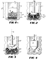
- Figs. 1-3
- are schematic illustrations of steps according to the method of the present invention for creating short aggregate piers in situ in the ground, and showing a portion of an apparatus used for carrying out the method.
- Fig. 4
- is a schematic illustration of an alternative apparatus for carrying out the method of Figs. 1-3.
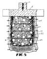
- Fig. 5
- is a side sectional illustration of a short aggregate pier produced in situ in the ground according to the present invention and supporting a structure thereon.
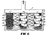
- Fig. 6
- is a side sectional view of several short aggregate pier produced in situ in the ground according to the present invention and supporting a structure thereon.
- Fig. 7
- is a schematic, partially cut-away, perspective illustration of a method and apparatus according to a second preferred form of the invention in which a large number of small aggregate piers are constructed simultaneously.
- Fig. 8
- is a side sectional illustration of a cavity created in accordance with the method and apparatus of Fig. 7.
- Fig. 9
- is a side sectional illustration of a short aggregate pier constructed in situ in the ground in accordance with the method and apparatus of Fig. 7.
- Figs. 10 and 11
- are graphs showing the results of field tests conducted to evaluate the present invention.
- Referring now in detail to the drawings, in which like reference numerals represent like parts throughout the several views, Figs. 1-3 depict a method and apparatus for constructing short aggregate piers according to a preferred form of the invention. As shown in Figs. 2 and 3, a
tamper apparatus 10 for constructing short aggregate piers includes an elongated support shaft 11 and a tampinghead 12. The tamper apparatus can be driven downwardly in any of a number of well-known, high-intensity techniques, such as for example being connected to a piston of a hydraulic ram and forced downwardly. Also, the support shaft can be struck with a falling weight to drive the tamping had downwardly, or can be driven by a pneumatic hammer. - The tamping
head 12 includes a generally flat, blunt bottom face indicated at 13 and a tapered surface indicated at 14. The flat bottom face 13 is adapted for compacting the soil and aggregate fill in a vertical direction, while the taperedsurface 14 is frusto-conical for tamping soil at a 45° angle, or other suitable angle, with respect tovertical axis 16 extending through the support shaft 11. - Fig. 4 shows an alternative embodiment of a tamper apparatus, specifically
apparatus 20. In this alternative embodiment, the tamper apparatus has a rather substantial andweighty body portion 21 which is lifted with a rope or chain orcable 22 and dropped or forced downwardly. Despite the different technique for raising and lowering thetamper apparatus 20, thetamper apparatus 20 shares important features withtamper apparatus 10. Namely,tamper apparatus 20 either includes a flat bottom surface 23 and a frusto-conical surface 24, or a spherical or near-spherical bottom surface. - Having now desribed the physical structure of two embodiments of a tamping apparatus useful for constructing in situ short aggregate piers according to the present invention, attention is now turned to the use of the tamping apparatus to construct such piers. Fig. 1 shows a hole or
cavity 31 which has been formed in an existingsoil 32. The hole orcavity 31 can be formed by any number of well-known techniques. For example, the cavity can be formed by use of an auger or by driving a mandrel, having a plow point at its lower end, into the ground. The cavity is excavated to a depth 33 and to a diameter 34. The depth 33 and the diameter 34 of the cavity are substantially the nominal dimensions of the ultimate short aggregate pier to be constructed, although the depth 33 may be increased by 30,48 cm (12 inches) or more by vertical compaction of the soil at the bottom of the cavity prior to placing the first layer of the aggregate fill. It should be noted that in considering the present invention, the cavity will be discussed as having a round cross-section and, therefore, having a diameter. However, other shapes of cavities can be constructed as the particular application requires. Indeed, it is contemplated by the present invention that elongated walls can be constructed according to the present invention. Nonetheless, for purposes of illustrating the invention, disussion will be limited to cylindrical piers. - With the
cavity 31 thus excavated, the first step according to the invention is to compact the soil at the bottom of the cavity to densify the soil directly beneath the bottom of the cavity. Compaction of the soil lining the bottom of the cavity is beneficial and increases the support capacity of the short aggregate pier. The result is a zone of prestressed and densified soil 36 adjacent and beneath the bottom of thecavity 31. - The next step is to fill a portion of the
cavity 31 with a quantity of loose, well-graded aggregate generally indicated at 37 in Fig. 1. Other granular material besides loose, well-graded aggregate can be used as the particular application requires. Well-graded aggregate is preferred because of the substantial strength imparted by the larger particles in the well-graded aggregate, with the smaller particles acting to fill the interstices between the larger particles quite effectively. The aggregate 37 is added to adepth 38 to create an uncompacted layer. Thedepth 38 preferably is 45,72 cm (18 inches), but can be between 15,24 cm (6 inches) and 91,44 cm (3 feet). - With a layer of aggregate partially filling a bottom portion of the cavity, the next step is to compact the aggregate with
te tamping apparatus 10 to highly densify the aggregate and to induce high-intensity lateral stresses in the soil laterally surrounding the cavity in the vicinity of thelayer 37 of aggregate. These lateral stresses prestress the soil while simultaneously densifying it. As shown in Fig. 2, the forces exerted on the aggregate and thereby on the surrounding soil, being tamped by operation of the tampingapparatus 10 tend to be normal to the surfaces of the tamping apparatus. Thus, the forces exerted by the flat bottom portion 13 tend to compress the aggregate vertically primarily, while the forces exerted on the aggregate by the frusto-conically taperedsurface 14 on the aggregate have both a vertical and a lateral component. Indeed, since the frusto-conical surface is at an approximate 45° angle with respect toaxis 16, which axis is co-incident with the axis of travel of the tamper apparatus in use, the magnitude of the lateral component of forces exerted on the aggregate by the conically tapered surface is equal to the magnitude of the vertical component of the force exerted on the aggregate. The resultant force of the lateral and vertical components exerted on the aggregate by the conically-taperedsurface 14 is depicted in Fig. 2 by force arrows 39.Force arrows 41 depict the vertical forces exerted by the bottom surface 13 acting on theaggregate 37. By operation of the tampingapparatus 10, theheight 38 of theaggregate layer 37 is reduced significantly. For example, the preferred uncompacted layer of aggregate would have initial height of 45,72 cm (18 inches) and after compaction would have a compacted height 42 which is some one-third less than theuncompacted height 38, in this case compacted height would be 30,48 cm (12 inches). - Since the
aggregate layer 37 is made up of a large number of granular elements which are able to move about relative to each other under pressure, thedownward force 41 exerted by the bottom surface 13 of the tamping apparatus causes some outward pressure on the sidewalls of the cavity. This outward pressure on the sidewalls of the cavity is greatly augmented by the horizontal components of forces 39, caused by the taperedsurface 14 acting on theaggregate layer 37. Indeed, the aggregate 37 bulges to a significant extent as indicated schematically in Figs. 2, 3 and 5. The lateral component of the forces 39 which cases the cavity to bulge also places great prestress on thesoil 32 in the vicinity of the now-compactedlayer 37 of aggregate. Indeed, the soil in a zone indicated at 43 positioned laterally of the soil/ aggregate interface is compacted and prestressed to a significant degree. The now-bulged layer oflift 37 of compacted aggregate is complete. - The tamping
apparatus 10 is then withdrawn from thecavity 31 and an additional layer of uncompacted, loose aggregate is added atop the compacted layer to an additional depth of, for example, 45,72 cm (18 inches). The new layer of loose aggregate is then similarly compacted to the reduced height of, for example, 30,48 cm (12 inches). This process is repeated until a series of bulged layers extends from the bottom of the cavity and completely fills the cavity as shown in Fig. 5, or fills the cavity to an extent desired. - As shown in Fig. 5, the
short aggregate pier 51 is generally cylindrical in overall shape, but having a series of bulges extending along its lenth.Aggregate pier 51, for example, comprises first, second, third and fourth lifts or layers 52-55. Each of these layers has a generally bulged shape. The resulting overall external surface has a greater surface area than a conventional deep stone column of the same nominal diameter having a cylindrical structure. This has important advantages as is discussed below. Also, by virtue of the construction of these bulges during compaction of the aggregate pier, the surrounding soil is prestressed and densified to a significant degree in the zone laterally adjacent the aggregate pier. This prestressing and densification of the surrounding soil is also very important and will be discussed in more detail below. Fig. 5 also shows that theaggregate pier 51 can be used to support a footer F for bearing the load of a building structure as indicated by the force arrow labelled L. - Fig. 6 shows a number of short aggregate piers constructed in situ in the ground and cooperating to support a footer F. While three aggregate piers 57-59 are shown in Fig. 6, any number of such piers can be used as the particular application requires.
- The applicants conducted two field studies related to the above-described invention. The preliminary field studies were conducted to evaluate the viability of using short aggregate piers to reinforce soils beneath shallow building foundations. Well-graded, aggregate base coarse stone was used in both field studies as the backfill material to make up the aggregate piers.
- In the first field study, a 60,96 cm (24 inches)-diameter field plate-load test was performed on each of three short aggregate piers constructed in situ in soil consisting primarily of firm sandy micaceous silts and construction debris which had been placed as an uncontrolled fill. Standard penetration blow counts of the near-surface matrix soil ranged from six to ten blows per 30,48 cm (1 foot) and averaged eight blows per 30,48 cm (1 foot). Two of the three test piers were compacted by dropping a cylindrical weight with a tapered bottom from a tripod. The tapered bottom induced high-intensity lateral stresses on the surrounding soil. These stresses prestressed and densified the laterally surrounding soil.
- In the third test, the aggregate was dumped into the cavity but was not compacted.
- Reactions for the loading tests were provided by jacking against the rear axle of a 10-ton truck loaded with weight. The maximum applied load using this method was 5443.2 kg (12 kips), which was insufficient to cause failure of the aggregate piers, but which was large enough to test the piers substantially above the design load of 12206,6 kg/m2 (2.5 ksf).
- The pressure-settlement curves from these three plateload tests are illustrated in Fig. 10. Curve A represents the results from the test on a 30,48 cm (1 foot) diameter by 60,96 cm (2 feet) deep aggregate pier in which the aggregate was not compacted. Curve B represents the results from the test on a 30,48 cm (1 foot) diameter by 60,96 cm (2 feet) deep aggregate pier in which the aggregate was heavily compacted in
layers - The results of these tests indicate that the observed settlements for the short aggregate piers under the design load of 12206,6 kg/m2 (2.5 ksf) were substantially less than the specified tolerable settlement of 1,27 cm (0.5 inches). Curves B and C are essentially the same, thereby indicating that the depth to diameter ratio or the height to diameter ratio of the short aggregate piers need be no greater than 2.0 to obtain maximum reinforcing effect in the soil. Constructing aggregate piers deeper than this for a given diameter is deemed to be uneconomical because little additional reinforcing effect is obtained with the additional cost associated with the larger pier. Comparison of Curves A and B illustrates the importance of prestressing and densifying the surrounding soil by high-intensity lateral stresses induced during compaction of the aggregate lifts. The compacted aggregate pier (Curve B) settled substantially less than the non-compacted aggregate pier (Curve A) at all applied pressures. For example, at the design pressure of 12206,6 kg/m2 (2.5 ksf), the compacted pier settled at 2,0 mm (0.08 inches), 78 percent less than the 9,lmm (0.36 inches) settlement for the non-compacted pier. In addition, the compacted aggregate pier remained stable at the maximum applied pressure of 73240 kg/m2 (15 ksf), whereas the non-compacted aggregate pier approched failure at an applied pressure of approximately 43944 kg/m2 (9 ksf).
- In the second field study, two 60,96 cm (24 inches)-diameter field plate-load tests were conducted. Reactions for the loading tests were provided by jacking against a steel beam load frame attached to four helical soil anchors. The first plate-load test was performed on unreinforced in situ soil consisting of firm sandy silt. Dynamic penetrometer blowcounts (per 4,44 cm (1.75 inches) increment) of the near-surface soil ranged from nine to thirteen and averaged ten. The second plate-load test was conducted on an aggregate pier having a diameter of 60,96 cm (2 feet) and depth of 1,524 m (5 feet). The initial cavity was 1,219 m (4 feet) deep but was enlarged to a depth of 1,524 m (5 feet) by compacting the soil at the bottom of the cavity using high energy impact compaction from a tamping head as shown at 12 in Fig. 2. High energy impact compaction from the same tamping head were used to compact aggregate in layers 45,72 cm (18 inches) thick (except the last of top layer which was compacted to a thickness of 30,48 cm (12 inches)), while simultaneously applying high intensity lateral stresses to the surrounding soil, which prestressed and densified the soil.
- Pressure-settlement curves for these two plate-load tests are given in Fig. 11. Curve D represents the results from the test on the unreiforced soil. Curve E represents the results from the test on the short aggregate pier. Comparison of the two curves illustrates the substantial reinforcing effect provided the short aggregate pier. Comparison of the two curves illustrates the substantial reinforcing effect provided the short aggregate pier. At all applied pressures the settlement of the short aggregate pier supported by the surrounding soil (Curve E) is substantially less than the settlement of the unreiforced soil (Curve D). For example, at an applied pressure of 48826.7 kg/m2 (10 ksf), the short aggregate pier settled 3,3 mm (0.13 inches), 80 percent less than the unreinforced soil which settled 16,2 mm (0.64 inches). In addition, the unreinforced soil approached failure at an applied pressure of approximately 53709.3 kg/m2 (11 ksf), whereas the short aggregate pier remained stable at an applied pressure of 12206.6 kg/m2 (25 ksf).
- The short aggregate pier can fail to support the required load by rupturing or by sliding relative to the soil surrounding the aggregate pier. In this regard, the interaction between the aggregate pier and the soil surrounding the pier is crucial. For example, the aggregate pier is made up of individual aggregate elements which are not adhered together. This cohesionless pier is prevented from rupturing under load largely by the lateral reaction forces exerted on the pier by the surrounding soil. Thus, the soil's local ability to bear force directly influences the aggregate pier's ability to resist rupturing. By prestressing and densifying the soil laterally adjacent the aggregate pier, the aggregate pier is better able to resist rupturing.
- The prestressing and densification of the soil laterally adjacent the short aggregate pier and beneath and adjacent the aggregate pier also tends to increase the load-bearing capacity of the aggregate pier by decreasing the tendency of the pier to slip in shear relative to the prestressed surrounding soil. This is so because the prestressed and densified soil laterally adjacent the aggregate pier tends to exert a tighter "grip" on the aggregate pier. This is analagous to trying to prevent a cylindrical object from slipping through one's hands by grasping the object more tightly. In effect, this is what the prestressed soil does. In addition, densification of the soil beneath the aggregate provides a firmer bearing surface for the aggregate pier, thereby further increasing the ability of the aggregate pier to support the required load.
- Another way in which the tendency of the short aggregate pier to slip in shear relative to the soil is diminished by the present invention is the shape of the interface between the aggregate pier and the soil laterally surrounding the pier. The aggregate pier has a series of bulges extending along the length of the pier and the prestressed and densified soil has a complementary shape. This shape exhibits a greater surface area than a conventional deep cylindrical stone column. Also, the bulges in the short aggregate pier act like shallow anchors dug into the compacted soil. For example, the prestressed and densified soil in the vicinity of the node indicated at 49 in Fig. 5 resists the movement of lift 53 downwardly therepast with compressive forces, in addition to the shear forces. This significantly enhances the resistance of the short aggregate pier to slip relative to the surrounding soil.
- Figs. 7-9 show a second preferred form of the invention. In this embodiment, a method and apparatus is provided which is intended, for example, for improving inadequate soils so that the soils can receive and support a layer of pavement. According to the method and apparatus, a tamping head indicated generally at 60 includes a platen 61 bearing a large number of individual probe elements for pricking the ground, such a
probe element 62. The probe elements are arranged in a grid pattern and are each generally cylindrical with a rounded portion indicated at 63. Each of the rigid probe elements has a diameter or preferably 5,08 cm (2 inches) and length of 15,24 cm (6 inches), the probe element, however, can be constructed to have diameters of between of 1,27 cm (0,5 inches) and 15,24 cm (6 inches), and lengths between 2,54 cm (1 inch) and 60,96 cm (24 inches). - The tamping
head 60 is attached to an unshown means for moving a tamping head up and down, as is well known in the art. In use, the tamping head is moved downwardly in the direction ofdirection arrows 66 to form a grid of cavities in unreinforced soil, as shown in the lower portion of Fig. 7. Thegrid 64 of cavities is made up of a large number of individual cavities, such ascavity 67 shown in Fig. 8. Each of the cavities is generally cylindrical with a beveled or roundedbottom portion 68. - In use, the tamping
head 60 is operated in a manner analagous to that of tampinghead 12. Specifically, the tamping is moved downwardly to form the grid ofcavities 64 and then is withdrawn. The cavities are then partially filled with loose granualar material and then the tamping head is lowered to reintroduce the individual probe elements into the cavities to compact the loose granular material in the cavities. The rounded tips of the probe elements compact the loose granular material both vertically and laterally, thereby bulging the cavity in the vicinity of the layer of granular material. As in the prior embodiment,probe element 62 can define a frusto-conical lower surface, similar tosurface 24, rather than defining arounded portion 63. The tamping head is then withdrawn and an additional layer of loose granular material is added and the compacting is repeated. The addition of loose granular material and the compaction of the loose granular material into successive layers is repeated until the cavity is filled substantially completely with compacted granular material. In this way, a small-scale aggregate pier results in each of the cavities, with each pier having the undulated, bulging shape similar to that shown in Fig. 9. - Optimum spacing of the probe elements is approximately four times the probe diameters but may vary from as low as two times the probe diameter to as great six times the probe diameter. Preferably, the grid includes sixty-four (64) probe elements, but may contain as few as four probe elements.
- The resulting grid of small-scale aggregate piers greatly increases the load-bearing capability of the soil, thereby making it suitable for roadway pavement support. The effectiveness of this method and apparatus was confirmed in a series of laboratory tests of the type know as California Bearing Ratio (CBR) tests. In these CBR tests, a grid of small-scale aggregate piers was constructed in CBR samples simulating bearing soils for ongrade construction. In these tests, soil was stabilized to form a soil/pier matrix in which the soil comprised soft clay stabilized with 1,27 cm (0,5 inches) diameter, 5,08 cm (2 inches) long piers constructed of well-graded sand, with the number of piers varying from one to thirteen.
- For these tests on the clay matrix, the increase in CBR ranged from 33% to 145% for eight tests, with no improvement for one sample of saturated clay reinforced with only one column. Although these sand elements were not highly compacted and did not induce high intensity passive pressures in the soil matrix, it is apparent that measurable improvents were achieved. The CBR values generally increased with increasing numbers of columns within the sample. The results from these laboratory tests demonstrated that a grid of small-scale granular element columns can be used to reinforce, stabilize, and improve matrix soils for on-grade construction.
Claims (17)
- A method of compacting the soil in order to improve its load bearing characteristics by mecanically lifting a weight and dropping it or by using another mechanical drive for a tamping implement to impact the ground at the same location, repeatedly, characterized by the following steps to produce at least one short aggregate pier (51, 57, 58, 59) in situ in the ground:(a) forming at least one cavity (31, 67) in the ground by making a hole;(b) compacting the soil (36) in the vicinity of a bottom portion (68) of the cavity (31, 67) to prestress and densify the soil (36) in that vicinity;(c) adding a layer (52) of loose aggregate (37) to partially fill in the cavity (31, 67):(d) compacting the layer (52) of aggregate (37) with the tamping implement (10, 20, 60) inserted into the cavity and having a tapered portion (14, 63) adapted to reduce the height (38) of the layer (52) and adapted to force some of the aggregate (37) laterally into the sides of the cavity (31, 67) and some of the aggregate downwardly and thereby to enlarge the cavity (31, 67) in the vicinity of the layer (52) and prestress and densify the soil (36) both at the bottom and along the sides of the cavity; and(e) repeating steps (c) and (d) until the cavity (31, 67) is filled substantially completely with compacted aggregate (37).
- The method as claimed in claim 1, wherein the step of compacting soil (36) in the vicinity of a bottom portion of the cavity (31, 67) is performed by driving the tamping implement (10, 20, 60) having the tapered portion (14, 63) into the cavity.
- The method as claimed in claim 1, wherein the layer of loose aggregate (37) is made up of well-graded stone.
- The method as claimed in claim 3, wherein the well-graded stone is added as a layer (52) approximately 45,7 cm (18 inches) in height (38).
- The method as claimed in claim 4, wherein the layer (52) of well-graded loose stone is compacted to reduce its height (38) to roughly 30,5 cm (12 inches).
- The method as claimed in claim 1, wherein the layer (52) of loose aggregate (37) is compacted to reduce its height (38) by approximately one third.
- The method as claimed in claim 1, wherein the cavity (31, 67) formed in the ground (32) according to step (a) has a length (33) to diameter (34) ratio of between 2.0 and 3.0.
- The method as claimed in claim 1, wherein the cavity (31, 67) formed in the ground (32) according to step (a) is between 91,44 cm (3 feet) and 3,048 m (10 feet) deep.
- The method as claimed in claim 1, wherein the cavity (31, 67) formed in the ground (32) according to step (a) is between 1,524 m (5 feet) and 1,828 m (6 feet) deep.
- The method as claimed in claim 1, wherein a plurality of cavities (67) are formed simultaneously in the ground (32) using ganged elements (62/63) and wherein aggregate (37) is added to each of the cavities (67) and is compacted simultaneously with the ganged elements (62/63).
- A tamper apparatus (10, 20, 60) for compacting the soil in order to improve its load bearing characteristics by mecanically lifting a weight and dropping it or by using another mecanical drive for a tamping implement to impact the ground (36) at the same location, repeatedly, according to the method as claimed in claims 1 to 10, characterized by a support member having a lower end and a tamping head (12, 60) mounted to that lower end for producing short aggregate piers (51, 57, 58, 59) in situ in the soil, said tamping head (12, 60) comprising a tapered portion (14, 63) adapted to displace some of the aggregate (37) laterally into the sides of the cavity (31, 67) and some of the aggregate downwardly and thereby to enlarge the cavity (31, 67) laterally adjacent the layer of loose aggregate (37) being compacted and to prestress and densify the soil both at the bottom and along the sides of the cavity.
- The apparatus as claimed in claim 11, wherein said tapered portion (14, 63) is frusto-conical to force some of the aggregate (37) laterally.
- The apparatus as claimed in claim 11, wherein said tamping head (12) comprises a flat bottom portion (13) adjacent said tapered portion (14).
- The apparatus as claimed in claim 11, wherein said tamping head (60) comprises a plurality of ganged elements (62/63), the ganged elements (62/63) each having a tapered portion (63) adapted to compact the granular material both vertically and laterally and thereby to prestress and densify the soil (36) laterally adjacent the layer (52) of granular material.
- The apparatus as claimed in claim 14, wherein the ganged elements (62/63) are regulary spaced in a grid pattern (64).
- The apparatus as claimed in claims 14 and 15, wherein the ganged elements (62/63) are each generally cylindrical with diameters of between 2,54 cm (1 inch) and 15,24 cm (6 inches).
- The apparatus as claimed in claims 14 and 15, wherein the ganged elements (62/63) are each generally cylindrical with diameters of between 5,08 cm (2 inches) and 7,62 cm (3 inches).
Applications Claiming Priority (3)
| Application Number | Priority Date | Filing Date | Title |
|---|---|---|---|
| US672701 | 1991-03-20 | ||
| US07/672,701 US5249892A (en) | 1991-03-20 | 1991-03-20 | Short aggregate piers and method and apparatus for producing same |
| PCT/US1992/002301 WO1992016695A1 (en) | 1991-03-20 | 1992-03-20 | Short aggregate piers and method and apparatus for producing same |
Publications (3)
| Publication Number | Publication Date |
|---|---|
| EP0533890A1 EP0533890A1 (en) | 1993-03-31 |
| EP0533890A4 EP0533890A4 (en) | 1993-08-11 |
| EP0533890B1 true EP0533890B1 (en) | 1996-12-11 |
Family
ID=24699652
Family Applications (1)
| Application Number | Title | Priority Date | Filing Date |
|---|---|---|---|
| EP92908717A Expired - Lifetime EP0533890B1 (en) | 1991-03-20 | 1992-03-20 | Short aggregate piers and method and apparatus for producing same |
Country Status (9)
| Country | Link |
|---|---|
| US (1) | US5249892A (en) |
| EP (1) | EP0533890B1 (en) |
| AT (1) | ATE146245T1 (en) |
| AU (1) | AU1568492A (en) |
| DE (1) | DE69215811T2 (en) |
| DK (1) | DK0533890T3 (en) |
| ES (1) | ES2097323T3 (en) |
| GR (1) | GR3022453T3 (en) |
| WO (1) | WO1992016695A1 (en) |
Cited By (2)
| Publication number | Priority date | Publication date | Assignee | Title |
|---|---|---|---|---|
| EP2386000A2 (en) * | 2009-01-09 | 2011-11-16 | Geopier Foundation Company, Inc. | Construction modulus testing apparatus and method |
| DE102010024607A1 (en) | 2010-06-22 | 2011-12-22 | Eduard Eigenschenk | Foundation pile for increasing load-carrying capacity in soil, has different layers provided with aggregate with geo-textile sacks, geo-textile trajectory and/or geo-textile fabric and between top/under-covered layers of thin aggregate |
Families Citing this family (44)
| Publication number | Priority date | Publication date | Assignee | Title |
|---|---|---|---|---|
| NL1000127C2 (en) * | 1994-04-15 | 1995-12-27 | Bekaert Sa Nv | Floor plate construction. |
| BE1013947A3 (en) * | 1994-04-15 | 2003-01-14 | Bekaert Sa Nv | Industrial concrete floor section - is supported by pillars of gravel formed in boreholes under floor section |
| ES2226165T3 (en) * | 1997-08-20 | 2005-03-16 | Roxbury Limited | LAND TREATMENT. |
| US6354766B1 (en) | 1999-02-09 | 2002-03-12 | Geotechnical Reinforcement Company, Inc. | Methods for forming a short aggregate pier and a product formed from said methods |
| US6354768B1 (en) * | 2000-01-24 | 2002-03-12 | Geotechnical Reinforcement Company, Inc. | Soil reinforcement method and apparatus |
| US9169611B2 (en) | 2000-06-15 | 2015-10-27 | Geopier Foundation Company, Inc. | Method and apparatus for building support piers from one or more successive lifts formed in a soil matrix |
| US7226246B2 (en) * | 2000-06-15 | 2007-06-05 | Geotechnical Reinforcement, Inc. | Apparatus and method for building support piers from one or successive lifts formed in a soil matrix |
| US8152415B2 (en) * | 2000-06-15 | 2012-04-10 | Geopier Foundation Company, Inc. | Method and apparatus for building support piers from one or more successive lifts formed in a soil matrix |
| EP1337717A4 (en) | 2000-06-15 | 2004-09-22 | Geotechnical Reinforcement Com | Lateral displacement pier and method of installing the same |
| GB2393979B (en) * | 2001-07-09 | 2004-11-03 | Three Dimensional Marketing Lt | Foundation structure, components therefor and method of constructing a foundation |
| GB2391036B (en) * | 2002-07-18 | 2005-05-04 | Roxbury Ltd | Ground improvement |
| RU2005121268A (en) * | 2002-12-06 | 2006-01-20 | Джиотекникал Рейнфорсмент, Инк. (Us) | METHOD FOR CONSTRUCTION OF SUPPORTS IN SOIL AND STRUCTURE OF SUPPORT |
| US7326004B2 (en) * | 2004-10-27 | 2008-02-05 | Geopier Foundation Company, Inc. | Apparatus for providing a rammed aggregate pier |
| US8043028B2 (en) * | 2004-10-27 | 2011-10-25 | Geopier Foundation Company, Inc. | Apparatus for providing a support column |
| US7963724B2 (en) * | 2004-10-27 | 2011-06-21 | Geopier Foundation Company, Inc. | Method of providing a support column |
| US7296475B2 (en) * | 2005-03-18 | 2007-11-20 | Conner Charles C | Displacement instrument for determining the modulus of a material |
| KR100979929B1 (en) | 2005-05-20 | 2010-09-03 | 지오피어 파운데이션 컴파니, 인코포레이티드 | Slotted mandral for lateral displacement pier and method of use |
| US7488139B2 (en) * | 2005-09-29 | 2009-02-10 | Geopier Foundation Company, Inc. | Pyramidal or conical shaped tamper heads and method of use for making rammed aggregate piers |
| US20080072656A1 (en) * | 2006-03-18 | 2008-03-27 | Conner Charles C | Displacement instrument |
| WO2008033139A1 (en) * | 2006-09-15 | 2008-03-20 | Conner Charles C | Pressure transducer for measuring hydraulic breaker displacement and determining aggregate modulus during compaction |
| ES2616524T3 (en) * | 2007-02-22 | 2017-06-13 | Geopier Foundation Company, Inc. | Method and apparatus for creating compacted aggregate piles using a hollow mandrel with upflow restrictors |
| US7931424B2 (en) * | 2008-06-16 | 2011-04-26 | GeoTech Goundation Company—West | Apparatus and method for producing soil columns |
| US8562258B2 (en) | 2008-07-29 | 2013-10-22 | Geopier Foundation Company, Inc. | Shielded tamper and method of use for making aggregate columns |
| MX2011000815A (en) * | 2008-07-29 | 2011-05-30 | Geopier Foundation Co Inc | Shielded tamper and method of use for making aggregate columns. |
| US8328470B2 (en) * | 2009-06-24 | 2012-12-11 | Geopier Foundation Company, Inc. | Apparatus and method for ground improvement |
| WO2011005386A2 (en) * | 2009-06-24 | 2011-01-13 | Geopier Foundation Company, Inc. | Apparatus and method for ground improvement |
| US8740501B2 (en) | 2009-06-24 | 2014-06-03 | Geopier Foundation Company, Inc. | Apparatus and method for ground improvement |
| US9915050B2 (en) * | 2009-06-24 | 2018-03-13 | Geopier Foundation Company, Inc. | Apparatus and method for ground improvement |
| WO2011001297A1 (en) * | 2009-06-30 | 2011-01-06 | Russet Trading & Investment 24 (Pty) Ltd | A method for constructing a column |
| US9637882B2 (en) | 2009-09-03 | 2017-05-02 | Geopier Foundation Company, Inc. | Method and apparatus for making an expanded base pier |
| US8974771B2 (en) * | 2010-03-09 | 2015-03-10 | Penn-Century, Inc. | Apparatus and method for aerosol delivery to the lungs or other locations of the body |
| DE202010014093U1 (en) | 2010-10-11 | 2010-12-30 | Sat Gmbh & Co. Kg | stamper |
| DE102010047915A1 (en) | 2010-10-11 | 2012-04-12 | Sat Gmbh & Co. Kg | stamper |
| US9207000B2 (en) | 2011-08-22 | 2015-12-08 | Darin Kruse | Solar apparatus support structures and systems |
| US8920077B2 (en) | 2011-08-22 | 2014-12-30 | Darin Kruse | Post tensioned foundations, apparatus and associated methods |
| ES2687788T3 (en) * | 2013-09-05 | 2018-10-29 | Geopier Foundation Company, Inc. | Methods and apparatus for compacting soil and granular materials |
| US11773555B2 (en) | 2013-09-05 | 2023-10-03 | Geopier Foundation Company, Inc. | Methods and apparatuses for compacting soil and granular materials |
| EP3041999A4 (en) | 2013-09-05 | 2017-05-03 | Geopier Foundation Company, Inc. | Apparatuses for constructing displacement aggregate piers |
| JP6544566B2 (en) * | 2015-05-01 | 2019-07-17 | 清水建設株式会社 | Countermeasures against liquefaction of existing structures |
| CA3011557C (en) | 2016-02-24 | 2021-01-12 | Ingios Geotechnics, Inc. | Systems and methods to provide pressed and aggregate filled concavities for improving ground stiffness and uniformity |
| EP3638854A4 (en) | 2017-06-12 | 2021-03-17 | PPI Engineering&Construction Services, LLC | Combination pier |
| RU197035U1 (en) * | 2019-12-30 | 2020-03-26 | Федеральное государственное автономное образовательное учреждение высшего образования "Сибирский федеральный университет" | DRILLING GROUND PILES |
| US11306544B2 (en) | 2020-04-14 | 2022-04-19 | Saudi Arabian Oil Company | Well pad construction system and methods |
| US20210355648A1 (en) * | 2020-08-01 | 2021-11-18 | Bahman Niroumand | Mandrel for soil compaction |
Family Cites Families (7)
| Publication number | Priority date | Publication date | Assignee | Title |
|---|---|---|---|---|
| US947548A (en) * | 1909-05-29 | 1910-01-25 | Arthur M Lind | Hand rammer and tamper. |
| US1764948A (en) * | 1929-06-14 | 1930-06-17 | Frankignoul Pieux Armes | Method for driving lining tubes for molding concrete piles in the ground |
| GB369816A (en) * | 1930-06-21 | 1932-03-31 | Frankignoul Pieux Armes | Improvements in and relating to the making of concrete piles in situ |
| US2917979A (en) * | 1956-02-27 | 1959-12-22 | Garlinghouse Brothers | Compactor |
| US3073124A (en) * | 1957-06-26 | 1963-01-15 | Nadal Jose Soler | Method for piles cast-in-situ |
| US3256790A (en) * | 1962-05-12 | 1966-06-21 | Buckau Wolf Maschf R | Self-propelling unit |
| US3909149A (en) * | 1971-11-01 | 1975-09-30 | Allied Steel Tractor Prod Inc | Hydraulic vibratory compactor |
-
1991
- 1991-03-20 US US07/672,701 patent/US5249892A/en not_active Expired - Lifetime
-
1992
- 1992-03-20 AU AU15684/92A patent/AU1568492A/en not_active Abandoned
- 1992-03-20 EP EP92908717A patent/EP0533890B1/en not_active Expired - Lifetime
- 1992-03-20 ES ES92908717T patent/ES2097323T3/en not_active Expired - Lifetime
- 1992-03-20 DE DE69215811T patent/DE69215811T2/en not_active Expired - Lifetime
- 1992-03-20 DK DK92908717.9T patent/DK0533890T3/en active
- 1992-03-20 AT AT92908717T patent/ATE146245T1/en not_active IP Right Cessation
- 1992-03-20 WO PCT/US1992/002301 patent/WO1992016695A1/en active IP Right Grant
-
1997
- 1997-01-31 GR GR970400164T patent/GR3022453T3/en unknown
Cited By (4)
| Publication number | Priority date | Publication date | Assignee | Title |
|---|---|---|---|---|
| EP2386000A2 (en) * | 2009-01-09 | 2011-11-16 | Geopier Foundation Company, Inc. | Construction modulus testing apparatus and method |
| EP2386000A4 (en) * | 2009-01-09 | 2013-01-09 | Geopier Found Co Inc | Construction modulus testing apparatus and method |
| DE102010024607A1 (en) | 2010-06-22 | 2011-12-22 | Eduard Eigenschenk | Foundation pile for increasing load-carrying capacity in soil, has different layers provided with aggregate with geo-textile sacks, geo-textile trajectory and/or geo-textile fabric and between top/under-covered layers of thin aggregate |
| DE102010024607B4 (en) * | 2010-06-22 | 2015-08-06 | Eduard Eigenschenk | Foundation pile and process for its production |
Also Published As
| Publication number | Publication date |
|---|---|
| ATE146245T1 (en) | 1996-12-15 |
| EP0533890A4 (en) | 1993-08-11 |
| DE69215811T2 (en) | 1997-04-03 |
| US5249892A (en) | 1993-10-05 |
| WO1992016695A1 (en) | 1992-10-01 |
| EP0533890A1 (en) | 1993-03-31 |
| ES2097323T3 (en) | 1997-04-01 |
| DE69215811D1 (en) | 1997-01-23 |
| DK0533890T3 (en) | 1997-06-09 |
| AU1568492A (en) | 1992-10-21 |
| GR3022453T3 (en) | 1997-04-30 |
Similar Documents
| Publication | Publication Date | Title |
|---|---|---|
| EP0533890B1 (en) | Short aggregate piers and method and apparatus for producing same | |
| EP1157169B1 (en) | Short aggregate pier techniques | |
| US7326004B2 (en) | Apparatus for providing a rammed aggregate pier | |
| EP1937900B1 (en) | Pyramidal or conical shaped tamper heads and method of use for making rammed aggregate piers | |
| US8221034B2 (en) | Methods of providing a support column | |
| CA2730150C (en) | Shielded tamper and method of use for making aggregate columns | |
| US9243379B2 (en) | Method of providing a support column | |
| WO2011153187A2 (en) | Method for ground improvement with hardened inclusions | |
| US8360689B2 (en) | Method for ground improvement with hardened inclusions | |
| CN105064332A (en) | Construction method for bearing base piles of square pile bodies | |
| Lutenegger | Uplift tests on shallow cast-in-place enlarged base pedestal foundations in clay | |
| CA2551216C (en) | Method and apparatus for providing a rammed aggregate pier | |
| CN114182593A (en) | Foundation reinforcing structure for enhancing anti-seismic performance of roadbed and construction method | |
| Ghanti et al. | Ground Improvement Techniques–with a Focused Study on Stone |
Legal Events
| Date | Code | Title | Description |
|---|---|---|---|
| PUAI | Public reference made under article 153(3) epc to a published international application that has entered the european phase |
Free format text: ORIGINAL CODE: 0009012 |
|
| AK | Designated contracting states |
Kind code of ref document: A1 Designated state(s): AT BE CH DE DK ES FR GB GR IT LI LU MC NL SE |
|
| 17P | Request for examination filed |
Effective date: 19930331 |
|
| A4 | Supplementary search report drawn up and despatched |
Effective date: 19930618 |
|
| AK | Designated contracting states |
Kind code of ref document: A4 Designated state(s): AT BE CH DE DK ES FR GB GR IT LI LU MC NL SE |
|
| 17Q | First examination report despatched |
Effective date: 19941021 |
|
| GRAG | Despatch of communication of intention to grant |
Free format text: ORIGINAL CODE: EPIDOS AGRA |
|
| GRAH | Despatch of communication of intention to grant a patent |
Free format text: ORIGINAL CODE: EPIDOS IGRA |
|
| GRAH | Despatch of communication of intention to grant a patent |
Free format text: ORIGINAL CODE: EPIDOS IGRA |
|
| ITF | It: translation for a ep patent filed |
Owner name: DE DOMINICIS & MAYER S.R.L. |
|
| GRAA | (expected) grant |
Free format text: ORIGINAL CODE: 0009210 |
|
| AK | Designated contracting states |
Kind code of ref document: B1 Designated state(s): AT BE CH DE DK ES FR GB GR IT LI LU MC NL SE |
|
| REF | Corresponds to: |
Ref document number: 146245 Country of ref document: AT Date of ref document: 19961215 Kind code of ref document: T |
|
| REG | Reference to a national code |
Ref country code: CH Ref legal event code: NV Representative=s name: DR. CONRAD A. RIEDERER PATENTANWALT |
|
| REF | Corresponds to: |
Ref document number: 69215811 Country of ref document: DE Date of ref document: 19970123 |
|
| ET | Fr: translation filed | ||
| REG | Reference to a national code |
Ref country code: GR Ref legal event code: FG4A Free format text: 3022453 |
|
| REG | Reference to a national code |
Ref country code: ES Ref legal event code: FG2A Ref document number: 2097323 Country of ref document: ES Kind code of ref document: T3 |
|
| REG | Reference to a national code |
Ref country code: DK Ref legal event code: T3 |
|
| PLBE | No opposition filed within time limit |
Free format text: ORIGINAL CODE: 0009261 |
|
| STAA | Information on the status of an ep patent application or granted ep patent |
Free format text: STATUS: NO OPPOSITION FILED WITHIN TIME LIMIT |
|
| 26N | No opposition filed | ||
| PGFP | Annual fee paid to national office [announced via postgrant information from national office to epo] |
Ref country code: SE Payment date: 19980420 Year of fee payment: 7 |
|
| PGFP | Annual fee paid to national office [announced via postgrant information from national office to epo] |
Ref country code: DK Payment date: 19980422 Year of fee payment: 7 Ref country code: AT Payment date: 19980422 Year of fee payment: 7 |
|
| PGFP | Annual fee paid to national office [announced via postgrant information from national office to epo] |
Ref country code: MC Payment date: 19980424 Year of fee payment: 7 |
|
| PGFP | Annual fee paid to national office [announced via postgrant information from national office to epo] |
Ref country code: GR Payment date: 19980430 Year of fee payment: 7 Ref country code: ES Payment date: 19980430 Year of fee payment: 7 |
|
| PGFP | Annual fee paid to national office [announced via postgrant information from national office to epo] |
Ref country code: BE Payment date: 19980513 Year of fee payment: 7 |
|
| PGFP | Annual fee paid to national office [announced via postgrant information from national office to epo] |
Ref country code: LU Payment date: 19980526 Year of fee payment: 7 |
|
| PG25 | Lapsed in a contracting state [announced via postgrant information from national office to epo] |
Ref country code: LU Free format text: LAPSE BECAUSE OF NON-PAYMENT OF DUE FEES Effective date: 19990320 Ref country code: AT Free format text: LAPSE BECAUSE OF NON-PAYMENT OF DUE FEES Effective date: 19990320 |
|
| PG25 | Lapsed in a contracting state [announced via postgrant information from national office to epo] |
Ref country code: SE Free format text: LAPSE BECAUSE OF NON-PAYMENT OF DUE FEES Effective date: 19990321 Ref country code: ES Free format text: LAPSE BECAUSE OF NON-PAYMENT OF DUE FEES Effective date: 19990321 |
|
| PG25 | Lapsed in a contracting state [announced via postgrant information from national office to epo] |
Ref country code: GR Free format text: LAPSE BECAUSE OF NON-PAYMENT OF DUE FEES Effective date: 19990331 Ref country code: DK Free format text: LAPSE BECAUSE OF NON-PAYMENT OF DUE FEES Effective date: 19990331 Ref country code: BE Free format text: LAPSE BECAUSE OF NON-PAYMENT OF DUE FEES Effective date: 19990331 |
|
| BERE | Be: lapsed |
Owner name: LAWTON EVERT Effective date: 19990331 Owner name: FOX NATHANIEL SILL Effective date: 19990331 |
|
| PG25 | Lapsed in a contracting state [announced via postgrant information from national office to epo] |
Ref country code: MC Free format text: LAPSE BECAUSE OF NON-PAYMENT OF DUE FEES Effective date: 19990930 |
|
| EUG | Se: european patent has lapsed |
Ref document number: 92908717.9 |
|
| EUG | Se: european patent has lapsed |
Ref document number: 92908717.9 |
|
| REG | Reference to a national code |
Ref country code: DK Ref legal event code: EBP |
|
| REG | Reference to a national code |
Ref country code: GB Ref legal event code: IF02 |
|
| PGFP | Annual fee paid to national office [announced via postgrant information from national office to epo] |
Ref country code: NL Payment date: 20020426 Year of fee payment: 11 |
|
| PGFP | Annual fee paid to national office [announced via postgrant information from national office to epo] |
Ref country code: CH Payment date: 20020521 Year of fee payment: 11 |
|
| PG25 | Lapsed in a contracting state [announced via postgrant information from national office to epo] |
Ref country code: LI Free format text: LAPSE BECAUSE OF NON-PAYMENT OF DUE FEES Effective date: 20030331 Ref country code: CH Free format text: LAPSE BECAUSE OF NON-PAYMENT OF DUE FEES Effective date: 20030331 |
|
| PG25 | Lapsed in a contracting state [announced via postgrant information from national office to epo] |
Ref country code: NL Free format text: LAPSE BECAUSE OF NON-PAYMENT OF DUE FEES Effective date: 20031001 |
|
| REG | Reference to a national code |
Ref country code: CH Ref legal event code: PL |
|
| NLV4 | Nl: lapsed or anulled due to non-payment of the annual fee |
Effective date: 20031001 |
|
| REG | Reference to a national code |
Ref country code: ES Ref legal event code: FD2A Effective date: 20000411 |
|
| REG | Reference to a national code |
Ref country code: GB Ref legal event code: 732E |
|
| REG | Reference to a national code |
Ref country code: FR Ref legal event code: TP Ref country code: FR Ref legal event code: CA |
|
| PGFP | Annual fee paid to national office [announced via postgrant information from national office to epo] |
Ref country code: GB Payment date: 20100108 Year of fee payment: 19 |
|
| PGFP | Annual fee paid to national office [announced via postgrant information from national office to epo] |
Ref country code: IT Payment date: 20110324 Year of fee payment: 20 |
|
| PGFP | Annual fee paid to national office [announced via postgrant information from national office to epo] |
Ref country code: DE Payment date: 20110329 Year of fee payment: 20 Ref country code: FR Payment date: 20110413 Year of fee payment: 20 |
|
| GBPC | Gb: european patent ceased through non-payment of renewal fee |
Effective date: 20110320 |
|
| PG25 | Lapsed in a contracting state [announced via postgrant information from national office to epo] |
Ref country code: GB Free format text: LAPSE BECAUSE OF NON-PAYMENT OF DUE FEES Effective date: 20110320 |
|
| REG | Reference to a national code |
Ref country code: DE Ref legal event code: R071 Ref document number: 69215811 Country of ref document: DE |
|
| REG | Reference to a national code |
Ref country code: DE Ref legal event code: R071 Ref document number: 69215811 Country of ref document: DE |
|
| PG25 | Lapsed in a contracting state [announced via postgrant information from national office to epo] |
Ref country code: DE Free format text: LAPSE BECAUSE OF EXPIRATION OF PROTECTION Effective date: 20120321 |