EP0532697B1 - Ellbogensystem mit laminarer strömung - Google Patents
Ellbogensystem mit laminarer strömung Download PDFInfo
- Publication number
- EP0532697B1 EP0532697B1 EP19910913881 EP91913881A EP0532697B1 EP 0532697 B1 EP0532697 B1 EP 0532697B1 EP 19910913881 EP19910913881 EP 19910913881 EP 91913881 A EP91913881 A EP 91913881A EP 0532697 B1 EP0532697 B1 EP 0532697B1
- Authority
- EP
- European Patent Office
- Prior art keywords
- fluid
- pipe section
- curved pipe
- rotation
- curved
- Prior art date
- Legal status (The legal status is an assumption and is not a legal conclusion. Google has not performed a legal analysis and makes no representation as to the accuracy of the status listed.)
- Expired - Lifetime
Links
- 238000000034 method Methods 0.000 claims abstract description 18
- 239000012530 fluid Substances 0.000 claims description 92
- 239000002245 particle Substances 0.000 claims description 21
- 238000000926 separation method Methods 0.000 claims description 12
- 238000013461 design Methods 0.000 abstract description 11
- 238000012795 verification Methods 0.000 abstract description 2
- 238000009434 installation Methods 0.000 abstract 1
- XLYOFNOQVPJJNP-UHFFFAOYSA-N water Substances O XLYOFNOQVPJJNP-UHFFFAOYSA-N 0.000 description 10
- 230000009466 transformation Effects 0.000 description 9
- 230000003628 erosive effect Effects 0.000 description 7
- 230000008602 contraction Effects 0.000 description 6
- 230000004907 flux Effects 0.000 description 6
- 230000001133 acceleration Effects 0.000 description 5
- 230000005514 two-phase flow Effects 0.000 description 5
- 150000001875 compounds Chemical class 0.000 description 4
- 210000002381 plasma Anatomy 0.000 description 4
- 230000008901 benefit Effects 0.000 description 3
- 238000009835 boiling Methods 0.000 description 3
- 239000000243 solution Substances 0.000 description 3
- 238000005336 cracking Methods 0.000 description 2
- 239000000975 dye Substances 0.000 description 2
- 230000000694 effects Effects 0.000 description 2
- 229910001149 41xx steel Inorganic materials 0.000 description 1
- 229920005479 Lucite® Polymers 0.000 description 1
- 241001272720 Medialuna californiensis Species 0.000 description 1
- RTAQQCXQSZGOHL-UHFFFAOYSA-N Titanium Chemical compound [Ti] RTAQQCXQSZGOHL-UHFFFAOYSA-N 0.000 description 1
- 238000009825 accumulation Methods 0.000 description 1
- 238000009530 blood pressure measurement Methods 0.000 description 1
- 239000003054 catalyst Substances 0.000 description 1
- 230000008859 change Effects 0.000 description 1
- 244000145845 chattering Species 0.000 description 1
- 230000005494 condensation Effects 0.000 description 1
- 238000009833 condensation Methods 0.000 description 1
- 238000001816 cooling Methods 0.000 description 1
- 239000000498 cooling water Substances 0.000 description 1
- 230000007423 decrease Effects 0.000 description 1
- 238000001704 evaporation Methods 0.000 description 1
- 230000008020 evaporation Effects 0.000 description 1
- 238000002474 experimental method Methods 0.000 description 1
- 239000007924 injection Substances 0.000 description 1
- 238000002347 injection Methods 0.000 description 1
- 239000007788 liquid Substances 0.000 description 1
- 238000012423 maintenance Methods 0.000 description 1
- 239000000463 material Substances 0.000 description 1
- 238000005259 measurement Methods 0.000 description 1
- 239000012071 phase Substances 0.000 description 1
- 239000004926 polymethyl methacrylate Substances 0.000 description 1
- 238000011084 recovery Methods 0.000 description 1
- 230000009467 reduction Effects 0.000 description 1
- 239000007787 solid Substances 0.000 description 1
- 229910001220 stainless steel Inorganic materials 0.000 description 1
- 239000010935 stainless steel Substances 0.000 description 1
- 239000000126 substance Substances 0.000 description 1
- 238000012360 testing method Methods 0.000 description 1
- 230000008719 thickening Effects 0.000 description 1
- 229910052719 titanium Inorganic materials 0.000 description 1
- 239000010936 titanium Substances 0.000 description 1
- 238000012546 transfer Methods 0.000 description 1
- 239000012808 vapor phase Substances 0.000 description 1
Images



Classifications
-
- F—MECHANICAL ENGINEERING; LIGHTING; HEATING; WEAPONS; BLASTING
- F16—ENGINEERING ELEMENTS AND UNITS; GENERAL MEASURES FOR PRODUCING AND MAINTAINING EFFECTIVE FUNCTIONING OF MACHINES OR INSTALLATIONS; THERMAL INSULATION IN GENERAL
- F16L—PIPES; JOINTS OR FITTINGS FOR PIPES; SUPPORTS FOR PIPES, CABLES OR PROTECTIVE TUBING; MEANS FOR THERMAL INSULATION IN GENERAL
- F16L43/00—Bends; Siphons
-
- F—MECHANICAL ENGINEERING; LIGHTING; HEATING; WEAPONS; BLASTING
- F15—FLUID-PRESSURE ACTUATORS; HYDRAULICS OR PNEUMATICS IN GENERAL
- F15D—FLUID DYNAMICS, i.e. METHODS OR MEANS FOR INFLUENCING THE FLOW OF GASES OR LIQUIDS
- F15D1/00—Influencing flow of fluids
- F15D1/02—Influencing flow of fluids in pipes or conduits
- F15D1/04—Arrangements of guide vanes in pipe elbows or duct bends; Construction of pipe conduit elements for elbows with respect to flow, e.g. for reducing losses of flow
-
- Y—GENERAL TAGGING OF NEW TECHNOLOGICAL DEVELOPMENTS; GENERAL TAGGING OF CROSS-SECTIONAL TECHNOLOGIES SPANNING OVER SEVERAL SECTIONS OF THE IPC; TECHNICAL SUBJECTS COVERED BY FORMER USPC CROSS-REFERENCE ART COLLECTIONS [XRACs] AND DIGESTS
- Y10—TECHNICAL SUBJECTS COVERED BY FORMER USPC
- Y10T—TECHNICAL SUBJECTS COVERED BY FORMER US CLASSIFICATION
- Y10T137/00—Fluid handling
- Y10T137/0318—Processes
- Y10T137/0324—With control of flow by a condition or characteristic of a fluid
- Y10T137/0357—For producing uniform flow
-
- Y—GENERAL TAGGING OF NEW TECHNOLOGICAL DEVELOPMENTS; GENERAL TAGGING OF CROSS-SECTIONAL TECHNOLOGIES SPANNING OVER SEVERAL SECTIONS OF THE IPC; TECHNICAL SUBJECTS COVERED BY FORMER USPC CROSS-REFERENCE ART COLLECTIONS [XRACs] AND DIGESTS
- Y10—TECHNICAL SUBJECTS COVERED BY FORMER USPC
- Y10T—TECHNICAL SUBJECTS COVERED BY FORMER US CLASSIFICATION
- Y10T137/00—Fluid handling
- Y10T137/0318—Processes
- Y10T137/0391—Affecting flow by the addition of material or energy
Definitions
- a new flow system and method have been invented to remove or to reduce flow separation and its induced turbulence and cavitation.
- Turbulence created in pipe elbows causes increased erosion, noise, vibration, and stress cracking. If an elbow is located too close to a check valve, it can cause chattering and damage to the valve seat. In the case of a nuclear power plant, it can threaten the safety of the plant. In a condenser cooling system, the turbulence causes uneven flow in the cooling water box, in turn reducing the heat transfer effectiveness, Erosion of an elbow in a wet steam line or in refinery piping carrying catalyst particulates can cause unexpected down time. In nuclear power plants, sometimes a double blanket “tee" is used to dampen the fluid impact during turns. Others have used a Vortex ball to absorb the impact energy in areas which normally have a high rate of erosion.
- US-A-1 974 110 upon which the preamble of claim 9 is based, discloses a method of transporting the fluid in a fluid flow path through a curved pipe section which comprises imparting rotation to the fluid prior to its entering the curved pipe section for reducing separation and turbulence of the fluid flow through the curved pipe section.
- My invention resulted from theoretical study and by reducing the problem to a geometrical problem known as rotational transformation in a magnetic confinement system of plasmas, first incorporated in the Stellarator, and used in many other areas of magnetic geometry with a stable plasma confinement.
- My invention recognizes the mathematic similarity of fluid flow streamlines and magnetic flux lines and their associated problems.
- Gradient B
- Plasma confined in such a field will be lost in a phenomena called Gradient (B) drift.
- This plasma with its loss of pressure and directed kinetic energy is similar to fluid flow and its elbow-induced turbulence.
- the rotational transformation in a magnetic field is a mathematic solution in that the magnetic flux is being rotated about the flux tube axis so that the flux lines going through a bend will have equal length.
- a method for reducing fluid turbulence in a curved pipe section comprising:
- a pipe comprising a substantially straight section followed by a curved section for the flow of a fluid therethrough, fluid-rotation-imparting means comprising turning vanes each having a leading edge and a trailing edge, being provided within the straight pipe section for impartment rotation to fluid about the axis of the straight pipe section in order to smooth the flow of fluid during its passage through the curved pipe section, the fluid-rotation-imparting means comprising a plurality of turning vanes, each having a curvature, the turning vanes being generally symmetrically positioned about the centre axis of the straight pipe section, each turning vane having a leading edge with no angle of attack relative to the fluid flow path and having a curvature in the direction of the fluid flow path, characterised in that where the angle of the turning vane to the wall of the straight pipe section is ⁇ the maximum angle of ⁇ for the turning vanes is substantially equal to 1 ⁇ 4 of the diameter of the straight pipe section multiplied by the inclusion angle of the
- the rotational transformation as invented here requires a pre-rotator before the fluid enters the elbow.
- the invented apparatus is called the Cheng Laminar Flow Elbow System, which consists of a pre-rotator and a matched elbow as a set.
- the pre-rotator is designed so that the flow streamlines going through the turn of an elbow will have equal length.
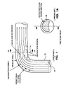
- Figure 1 is an illustration of the actual flow streamline as viewed through experimental photographs of real flows of pipes with dye injections.
- Figure 1A is a cross sectional view of the pipe shown in Figure 1.
- Figure 2A is an illustration of pressure distribution and secondary flow in a 90° turn elbow and its pressure distribution at the outer wall of the elbow and the inner wall of the elbow to indicate the cause of induced secondary flow in the separation.
- Figure 2B is a cross sectional view of the pipe shown in Figure 2A.
- Figure 3 is an illustration of sub-cooled water feed pumps through an elbow that go through a vapor phase cavitation and recovery cycle in accordance with Figure 2.
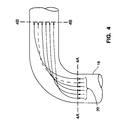
- Figure 4 is an illustration of equal streamline length flow desired to achieve rotational transformation mathematically.
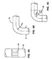
- Figure 5A is a partial side view of a pre-rotator in an embodiment of the present invention.
- Figure 5B is a partial side view of a pipe elbow in an embodiment of the present invention.
- Figure 5C is another partial side view of a pipe elbow in an embodiement of the present invention.
- Figure 6A illustrates a side view of a pre-rotator according to a rotational transformed solution that totally compensates the rotation induced by elbow flows.
- Figure 6B is a cross sectional view of the pre-rotator depicted in Figure 6A.
- Figures 7A and 7B are side sectional views of pipe elbows illustrating the comparison between an elbow with a rotational turning vane and an elbow without a rotational turning vane as experimentally determined employing an embodiment of the present invention.
- Figure 8A is a partial sectional view of a turning vane at its maximum turning angle in an embodiment of the present invention.
- Figure 8B sets forth formulas giving the relationship between the turning vane angle and the radius of the turning vane relating to the diameter of the particulate size of steam droplet size and the flow velocity such that the particle will not be separated from the main flow.
- Figure 1 illustrates the streamlines inside a pipe with an elbow.
- the streamline shape was photographed through a movie picture, and the streamlines were injected with colored dyes in a transparent Lucite pipe 10.
- the streamlines are bunched together at 12.
- the cross section of the pipe 14 downstream of the elbow is depicted as cross section 1A.
- Cross section 1A is the smallest area the flow has contracted to.
- the cross sectional view of the pipe is shown separately in Figure 1A.
- the shaded area 16 is shaped like a half moon.
- the contraction is similar to an orifice plate, and the streamline pulling from the outside wall of the pipe had never been observed by anyone prior to our experiment.
- the reason the streamline is pulling away from the outside wall is because the contraction due to acceleration of the fluid through a smaller area has to follow a certain streamline pattern, and the acceleration to the small area causes the fluid to separate from the outside wall.
- This separation region also causes accumulation of droplets and particulates, and is damaging to pipes.
- the separation of the inside wall of the elbow generates turbulence, cavitation, stress and noise downstream of the elbow.
- Figure 2A further illustrates the pressure measurement across the inner and outer wall of an elbow through a liquid fluid at a relatively high speed.
- the elbow pressure is measured at the locations on the inside wall labeled 1, 2, 3, 4, 5; and on the outside wall labeled as 1, A and 5.
- B coincides with position 3.
- the cross section 2B is shown in Figure 2B.
- the pressure distribution measured was a classical case; for instance, the outside of the pipe on the upper part of the curve, which is normalized by the kinetic head and pressure head, starts at 1, and increases to a higher level at point A. This is due to the stagnation and the centrifugal force, which then accelerates the fluid from A to position 5; therefore, the pressure drops dramatically. This acceleration is due to the contraction of the fluid after the elbow.
- the water pressure is high; therefore, it's called subcooled water below the boiling temperature of the fluid.
- the pressure and the boiling temperature curve is shown as a curve separating the points 1, 2, 3, 4, 5.
- the points 1, 2, 3, 4, 5 correspond to the points 1, 2, 3, 4, 5 in Figure 2A.
- the pressure is dropped from point 1 to point 2, which reaches the boiling temperature of the water under a lower pressure, the water is ready to be flashed into steam, which will continue to drop the pressure to point 3, which is clearly the vapor and steam phase. This is known as cavitation. It could happen not necessarily in a heated water situation. It is also caused by dissolved gas in water.
- the pressure is then recovered from point 3 to reach the condensation point under a lower temperature at point 4, then point 2.
- the elbow system 18 would require a different streamline pattern as depicted by 20.
- the streamline would require the same length starting from cross section 4A, and would reach cross section 4B at the same time and at the same velocity by designing a pre-rotational flow according to the rotational transformation formula.
- the streamline is more complicated than this; however, this illustrates a typical 90 degree turn elbow only.
- a feature of the pre-rotator under the rotational transformation rule is that the streamline started on the outermost wall of the pipe, after going through the elbow, reaches the innermost wall of the elbow, and the streamline on the innermost wall of the elbow will reach the outermost position after going through the elbow.
- the inside streamlines generally have no change in position; in other words, no rotation occurs at the center lines.
- the fluid stops rotation all by itself, and the fluid in the pipe is going straight beyond that point.
- turbulence is not generated through the elbow, and cavitation on the inside and outside is totally eliminated.
- the velocity of the fluid going through the elbow maintains a constant pace without acceleration or deceleration, which is the main cause of the droplets carried by the fluid to be separated from the main bodies.
- Figures 5A, 5B and 5C are illustrations of the pre-rotator and its relationship to the elbow turns.
- the pre-rotator 26 is located in the pipe ahead of the elbow 24.
- the relationship of the turning angle will be shown later; however, the relationship relates to the geometry of the elbow 22 according to the diameter of the elbow D and the turning radius R 10 .
- 28 is the center of the rotation of the elbow.
- Figures 6A and 6B illustrate the results of a typical geometry viewed in the direction of the fluid flow, and also on the side.
- the turning vane has a compound curvature that is a result of the rotation in the axial direction and also in the A direction.
- the angle is called a Theta
- R 30 we can see the fluid goes into the turning vane without any angle of attack, coming out with a maximum angle of turn, Theta max, and the radius for the fluid to reach the Theta max is called R 30 .
- the Theta max is equal to one quarter the pipe diameter divided by the radius of the turn (R 10 ) times the total inclusion angle of the turn (Phi)
- Rhi the total inclusion angle of the turn
- Theta 1 For any angle in between the center line to the outer edge (Theta 1), simply substitute the pipe diameter with the appropriate diameter (D1).
- the projected view would have a compound curve, as shown in cross section 6B.
- the radius of curvature R 30 is arbitrary if no two-phase flow problem is considered. It is also a critical design parameter when wet steam is flowing through the turning vane.
- Separate droplets or particles will be carried by the stream under a relatively small velocity to the stream, called a slip stream, such that the centrifugal force should be smaller than the slip stream so the particles will be rotating with the fluid instead of separating from the streamline and hitting the wall.
- the radius (R 30 ) relates to the maximum diameter of the particle the stream is carrying.
- Figures 7A and 7B are a set of actual experimental measurements of the same elbow with and without rotational transformed turning vanes ahead of the elbow.
- 7A shows the pressure distribution measured on the inside and outside wall of the elbow. The pressure is measured by pressure taps and manometer boards. It can be shown that the pressure distribution is very uniform from the inside and outside of the pipe flows, in contrast to Figure 7B, where the pressure is increased on the outside wall and is also creating almost a suction on the inside wall. This is the classical case as depicted in Figures 2A and 3.
- the pipe elbow shown in 7A there is no deviation in pressure through the elbow.
- the pressure loss of flow in an elbow is usually measured in the industry in terms of the equivalent pipe length for the same pressure loss according to the diameter of the pipe.
- Figure 8A shows the section of a turning vane 30 at the maximum turning angle.
- the turning radius is R 30 .
- the velocity of the flow stream is V f
- the diameter of the largest particle or droplets carried by the stream is d.
- the relative velocity going across the streamline is V v .
- the radius R 30 is designed such that the largest particle carried by the stream will not hit the wall, or at least will minimize the percentage of the largest droplet carried by the fluid to hit the turning vane wall.
- the reason the particle can be carried by the bulk of the stream is that the relative velocity of the particle and the stream is very small.
- the viscous force which is the reason that the particles are carried by the fluid stream, can be quantified through the drag coefficient, as measured by the Reynolds number, based on the relative streams and the diameter of the particles.
- the larger the Reynolds number the smaller the drag forces.
- the Reynolds number is a function of the density, the velocity and the particle diameter divided by the viscosity of the fluid. Therefore, the basic formula as given in Figure 8B is that the drag coefficient in the region allows particles to be carried by the stream, called Stoke's flow regime.
- the drag coefficient (C o ) is equal to 30 divided by the Reynolds number (R ed ).
- the drag force is equal to 15 times the density of the fluid ( ⁇ f ), the main velocity of the stream (V f 2 ) times Pi, times the diameter (d) of the particulates squared, divided by the Reynolds number (R ed ) Basically, this sets up a very unstable situation such that the larger the Reynolds number, the smaller will be the drag forces.
- the particulate can be carried by the stream as long as the relative velocity of the particles with respect to the fluid is small.
- the relative velocity becomes increased, and the Reynolds number also is increased. This in turn reduces the drag forces to hold onto the particle, which can cause an unstable runaway situation.
- the centrifugal force, however, caused by the turning vane can be shown in the equation as F c.f. equals the density of the particulates ( ⁇ s ) times 4 Pi divided by 3, the diameter cubed times the relative velocity squared divided by the radius of curvature of the turning vane (R 30 ). If the Reynolds number chosen still has a relatively large viscous force to retain the particles, then we can determine the relationship between the diameter and the turning radius of the vane designs. If we equate the viscous force drag and the centrifugal force to obtain a Reynolds number, we will find the equation as shown should be less than 100 to retain the relatively high viscous forces within the Stoke's flow regime.
- This Reynolds number is independent of the flow stream velocity, but is equal to the density of the solid to the density of fluid ratio, and the particulate size divided by the turning radius (R 30 ). This will be the criteria I use to design the turning vanes for two-phase flow.
- the rotational transformed turning vane is a geometrical effect independent of the velocity of flow through the pipe system; therefore, the turning angle does not have to be changed in various operations of higher or lower velocities within the same pipe system.
- the turning vane design is not an arbitrary design such that just rotating some fluid flow with certain plates would make the whole system work. The system has been tested in water tunnels extensively with a velocity range varied to a factor of 100. It definitely shows that the separation region of the elbow has been totally removed and the turbulence induced by the pipe flow has been removed.
- the maximum turning angle can be less than what I have shown in the formula. If the fluid is highly viscous or of very high velocity, then a careful trade-off between the pressure loss induced by the turning vane versus pressure reduction due to the turning vane would have to occur. It is also shown that the turning vane design is a compound surface whereby the fluid is rotated about the axis, and in the meantime, rotating perpendicular to the axis. The entrance into the rotation perpendicular to the axis will depend on the droplet size criteria, so a gentle entrance curve is recommended.
- the summary of my invention is the discovery under the fundamental fluid dynamic principle that under the rotational transformation calculation of Curl function, that a turning vane can be designed to compensate the forced rotation of fluid through an elbow.
- the geometrical relationship of the turn in terms of the diameter of the pipe and the turning radius therefore relating to the turning vane design has been an important discovery, and verification experimentally has borne the theory out.
- the scope of the invention is trying to eliminate cavitation, turbulence induced by the elbow flow, erosion due to these phenomena in pipe flows, and application to two-phase flows that the fluid can carry droplets or particulates in its streams.
- the scope of the invention is not only to reduce the pressure loss and increase the energy efficiency of pipe systems, but also to reduce noise generated and the weight of the piping systems, and enhance the safety of such systems.
Landscapes
- Engineering & Computer Science (AREA)
- General Engineering & Computer Science (AREA)
- Mechanical Engineering (AREA)
- Physics & Mathematics (AREA)
- Fluid Mechanics (AREA)
- Pipe Accessories (AREA)
- Branch Pipes, Bends, And The Like (AREA)
- Jet Pumps And Other Pumps (AREA)
- Paper (AREA)
- Cyclones (AREA)
- Physical Or Chemical Processes And Apparatus (AREA)
- Sink And Installation For Waste Water (AREA)
Claims (12)
- Ein Verfahren zum Reduzieren von Fluidturbulenz in einem gekrümmten Leitungsabschnitt (18, 22), wobei das Verfahren aufweist:Installieren eines Vor-Rotator-Umlenkblechs (26) vor dem gekrümmten Leitungsabschnitt;Strömen von Fluid an dem Vor-Rotator-Umlenkblech vorbei; undAuferlegen einer Rotation dem Fluid vor seinem Eintreten in den gekrümmten Leitungsabschnitt, um Separation und Turbulenz des Fluidstroms durch den gekrümmten Leitungsabschnitt zu reduzieren;wobei die Rotation, die dem strömenden Fluid durch das Vor-Rotator-Umlenkblech auferlegt wird, die Separation des Fluids von der Innenseite und der Außenseite des gekrümmten Abschnitts des gekrümmten Leitungsabschnitts minimiert, ein Strömungsprofil des genannten Fluids durch den gekrümmten Leitungsabschnitt mit im wesentlichen gleichförmiger Geschwindigkeit liefert und im wesentlichen nach Austritt aus dem gekrümmten Leitungabschnitt beendet wird.
- Ein Verfahren nach Anspruch 1, bei welchem die dem Fluid vor seinem Eintreten in den gekrümmten Abschnitt (18, 22) auferlegte Rotation eine Zweikomponenten-Vektor-Rotation des Fluids vor dem Eintreten in den gekrümmten Leitungsabschnitt ergibt, um die Wirbelfunktion des Fluids in dem gekrümmten Leitungsabschnitt im wesentlichen zu überwinden.
- Ein Verfahren nach Anspruch 1 oder 2, bei welchem die Fluidrotation mit Hilfe einer Mehrzahl von festen, im allgemeinen symmetrischen Umlenkblechen (26) in einem geraden Leitungsabschnitt genau vor dem gekrümmten Leitungsabschnitt (18, 22) vorgesehen wird.
- Ein Verfahren nach Anspruch 3, bei welchem der Winkel der Umlenkbleche (26) in Bezug auf die Wand des geraden Leitungsabschnitts einen maximalen Winkel aufweist, der im wesentlichen gleich 1/4 des Durchmessers (D) des geraden Leitungsabschnitts multipliziert mit dem Inklusionswinkel (R10) des gekrümmten Leitungsabschnitts und geteilt durch den Radius des gekrümmten Leitungsabschnitts ist.
- Ein Verfahren nach einem der vorhergehenden Ansprüche, bei welchem das Fluid ein Zweiphasenfluid mit Tröpfchen oder Teilchen in dem genannten Fluid aufweist.
- Ein Verfahren nach einem der Ansprüche 1 bis 4, bei welchem das Fluid einen Flüssig-Gas-Fluidstrom aufweist.
- Ein Verfahren nach Anspruch 5 oder 6, bei welchem das transportierte Fluid eine relative Reynoldsche' Zahl aufweist, welche auf Hauptstromeigenschaften in der Dichte, der Viskosität, dem maximalen Teilchendurchmesser und dem Teilchenverlust relativ zu dem Hauptstrom beruht, derart, daß 4/45-mal das Verhältnis von Teilchendichte zu Fluiddichte mal Teilchendurchmesser geteilt durch den minimalen Umlenkblech-Krümmungsradius kleiner als 100 ist.
- Ein Verfahren nach einem der vorhergehenden Ansprüche, bei welchem die Effektivität der Rotation des Fluids durch Messen des Druckdifferentials des Fluids zwischen der Innenwand und der Außenwand des gekrümmten Leitungsabschnitts überwacht wird.
- Eine Leitung mit einem im wesentlichen geraden Abschnitt, auf welchen ein gekrümmter Abschnitt (18, 22) folgt, für den Strom eines Fluids hierdurch, wobei eine Fluidrotations-Auferlegungseinrichtung (26) mit Umlenkblechen, von denen jedes einen vorderen Rand und einen hinteren Rand aufweist, innerhalb des geraden Leitungsabschnitts vorgesehen ist, um dem Fluid eine Rotation um die Achse des geraden Leitungsabschnitts aufzuerlegen, damit der Strom des Fluids während seiner Passage durch den gekrümmten Leitungsabschnitt beruhigt wird, wobei die Fluidrotations-Auferlegungseinrichtung eine Mehrzahl von Umlenkblechen aufweisen, von denen jedes eine Krümmung aufweist, wobei die Umlenkbleche im wesentlichen symmetrisch um die Mittelachse des geraden Leitungsabschnitts herum positioniert sind und wobei jedes Umlenkblech einen vorderen Rand mit keinem Anstellwinkel relativ zu dem Fluidströmungsweg und eine Krümmung in der Richtung des Fluidströmungswegs aufweist, dadurch gekennzeichnet, daß, wenn der Winkel des Umlenkblechs gegenüber der Wand des geraden Leitungsabschnitts ist, der maximale Winkel von für die Umlenkbleche im wesentlichen gleich 1/4 des Durchmessers (D) des geraden Leitungsabschnitts, multipliziert mit dem Inklusionswinkel (Φ) des gekrümmten Leitungsabschnitts (18, 22) und dividiert durch den mittleren Radius (R10) des gekrümmten Leitungsabschnitts ist, so daß die Rotationseinrichtung dazu befähigt ist, eine ausreichende Rotation dem Fluid vor dem Eintreten in den gekrümmten Leitungsabschnitt aufzuerlegen, um die Fluidturbulenz in dem gekrümmten Leitungsabschnitt zu minimieren, während vorgesehen ist, daß die Fluidrotation des Fluids im wesentlichen nach Austritt aus dem gekrümmten Leitungsabschnitt beendet ist.
- Eine Leitung nach Anspruch 9, bei welcher die Fluidrotations-Auferlegungseinrichtung (26) dazu befähigt ist, eine Zweikomponenten-Vektor-Rotation des Fluids vor dem Eintreten in den gekrümmten Leitungsabschnitt zu ergeben, um die Wirbelfunktion des Fluids in dem gekrümmten Leitungsabschnitt im wesentlichen zu überwinden.
- Ein Verfahren nach einem der Ansprüche 1 bis 8 oder eine Leitung nach Anspruch 9 oder 10, wobei bei diesem Verfahren oder bei dieser Leitung die Leitung von einem kreisförmigen Querschnitt ist.
- Ein Verfahren oder eine Leitung nach Anspruch 11, wobei bei diesem Verfahren oder bei dieser Leitung der gekrümmte Leitungsabschnitt (18, 22) um im wesentlichen 90° gekrümmt ist.
Applications Claiming Priority (3)
| Application Number | Priority Date | Filing Date | Title |
|---|---|---|---|
| US07/534,146 US5197509A (en) | 1990-06-06 | 1990-06-06 | Laminar flow elbow system and method |
| US534146 | 1990-06-06 | ||
| PCT/US1991/003865 WO1991019180A1 (en) | 1990-06-06 | 1991-05-31 | Laminar flow elbow system |
Publications (3)
| Publication Number | Publication Date |
|---|---|
| EP0532697A1 EP0532697A1 (de) | 1993-03-24 |
| EP0532697A4 EP0532697A4 (en) | 1993-08-04 |
| EP0532697B1 true EP0532697B1 (de) | 1998-03-04 |
Family
ID=24128866
Family Applications (1)
| Application Number | Title | Priority Date | Filing Date |
|---|---|---|---|
| EP19910913881 Expired - Lifetime EP0532697B1 (de) | 1990-06-06 | 1991-05-31 | Ellbogensystem mit laminarer strömung |
Country Status (10)
| Country | Link |
|---|---|
| US (2) | US5197509A (de) |
| EP (1) | EP0532697B1 (de) |
| JP (1) | JP2517507B2 (de) |
| AT (1) | ATE163760T1 (de) |
| AU (1) | AU660934B2 (de) |
| CA (1) | CA2084682A1 (de) |
| DE (1) | DE69129024T2 (de) |
| IE (1) | IE911822A1 (de) |
| IL (1) | IL98317A0 (de) |
| WO (1) | WO1991019180A1 (de) |
Cited By (1)
| Publication number | Priority date | Publication date | Assignee | Title |
|---|---|---|---|---|
| EP3835020B1 (de) | 2019-12-10 | 2024-08-28 | Saint-Gobain Placo | Schlauch |
Families Citing this family (60)
| Publication number | Priority date | Publication date | Assignee | Title |
|---|---|---|---|---|
| US5529084A (en) * | 1994-03-24 | 1996-06-25 | Koch Engineering Company, Inc. | Laminar flow elbow system and method |
| US5662079A (en) * | 1994-06-27 | 1997-09-02 | Snider; John Michael | Manifold flow turning vanes in internal combustion engines |
| US5641915A (en) * | 1995-02-03 | 1997-06-24 | Lockheed Idaho Technologies Company | Device and method for measuring multi-phase fluid flow in a conduit using an elbow flow meter |
| US5905208A (en) * | 1995-02-03 | 1999-05-18 | Lockheed Martin Idhao Technologies Company | System and method measuring fluid flow in a conduit |
| USD386137S (en) * | 1996-03-22 | 1997-11-11 | Camco Manufacturing, Inc. | RV generator exhaust coupler |
| US5839473A (en) * | 1996-06-20 | 1998-11-24 | Camco Manufacturing Inc. | RV generator auxiliary exhaust system and method |
| US5992465A (en) * | 1996-08-02 | 1999-11-30 | Jansen; Robert C. | Flow system for pipes, pipe fittings, ducts and ducting elements |
| DE19733941A1 (de) * | 1997-08-06 | 1999-02-11 | Klein Schanzlin & Becker Ag | Leitvorrichtung für Rohrleitungskrümmer |
| EP0918146A1 (de) | 1997-11-19 | 1999-05-26 | Sulzer Chemtech AG | Einrichtung zum Abbau von Schadstoffen in Abgasen mittels Katalysatoren |
| US6455644B1 (en) | 2000-02-28 | 2002-09-24 | Union Carbide Chemicals & Plastics Technology Corporation | Polyolefin production using condensing mode in fluidized beds, with liquid phase enrichment and bed injection |
| US6815512B2 (en) | 2000-02-28 | 2004-11-09 | Union Carbide Chemicals & Plastics Technology Corporation | Polyolefin production using condensing mode in fluidized beds, with liquid phase enrichment and bed injection |
| GB0009890D0 (en) * | 2000-04-20 | 2000-06-07 | Thames Water Utilities | Flow deflecting device |
| SE522546C2 (sv) * | 2001-02-21 | 2004-02-17 | Volvo Lastvagnar Ab | Anordning för dämpning av resonans i en rörledning |
| US6668580B2 (en) * | 2002-04-16 | 2003-12-30 | Carrier Corporation | Chiller compressor circuit containing turning vanes |
| US6880860B2 (en) * | 2002-10-31 | 2005-04-19 | Maria D. Atwood | Fluid conducting elbow |
| US6973825B2 (en) * | 2003-02-24 | 2005-12-13 | Visteon Global Technologies, Inc. | Hot-wire mass flow sensor with low-loss bypass passage |
| US7347223B2 (en) * | 2003-07-21 | 2008-03-25 | The Metraflex Company | Pipe flow stabilizer |
| US20050035592A1 (en) * | 2003-08-06 | 2005-02-17 | Williams Larry Franklin | Smooth flow pipe connector for lawn sprinkler system |
| US7185548B2 (en) * | 2005-04-18 | 2007-03-06 | Penlerick Delwin T | Apparatus and method for measuring flow between ends of a break in a fluid line |
| US7641720B2 (en) * | 2006-08-07 | 2010-01-05 | Gm Global Technology Operations, Inc. | Flow turning vane assembly with integrated hydrocarbon adsorbent |
| US8124030B2 (en) * | 2007-05-08 | 2012-02-28 | The Regents Of The University Of California | Microfluidic device having regulated fluid transfer between elements located therein |
| US8061117B2 (en) | 2007-06-01 | 2011-11-22 | Cheng Power Systems, Inc. | Dynamic control system to implement homogenous mixing of diluent and fuel to enable gas turbine combustion systems to reach and maintain low emission levels |
| US9079203B2 (en) | 2007-06-15 | 2015-07-14 | Cheng Power Systems, Inc. | Method and apparatus for balancing flow through fuel nozzles |
| US7981377B2 (en) * | 2007-11-06 | 2011-07-19 | Fina Technology, Inc. | Dehydrogenation of alkyl aromatics |
| US20090230674A1 (en) * | 2008-03-14 | 2009-09-17 | Gm Global Technology Operations, Inc. | Fuel Port Elbow Having a Truncated Conductive Insert Tube |
| US8961789B2 (en) * | 2008-10-31 | 2015-02-24 | Baxter International Inc. | Systems and methods for performing hemodialysis |
| US8651800B2 (en) | 2010-06-04 | 2014-02-18 | Gm Global Technology Operations Llp | Induction system with air flow rotation and noise absorber for turbocharger applications |
| CN101900154B (zh) * | 2010-08-04 | 2014-04-09 | 南京工业大学 | 节能防腐型平衡流场扰流子 |
| CN101963171B (zh) * | 2010-10-26 | 2012-02-01 | 西安建筑科技大学 | 一种矩形断面t型分流整流三通 |
| CN101975205B (zh) * | 2010-10-26 | 2012-02-01 | 西安建筑科技大学 | 一种矩形断面z型整流弯管 |
| CN101963172B (zh) * | 2010-10-26 | 2012-02-08 | 西安建筑科技大学 | 一种矩形断面п型180°整流弯管 |
| CN101963169B (zh) * | 2010-10-26 | 2012-02-01 | 西安建筑科技大学 | 一种90°整流矩形弯管 |
| CN101963170B (zh) * | 2010-10-26 | 2012-02-01 | 西安建筑科技大学 | 一种矩形断面十字型分流整流四通 |
| CN101968146B (zh) * | 2010-10-26 | 2012-02-01 | 西安建筑科技大学 | 一种矩形风管y形对称燕尾分流整流三通 |
| CN101975321B (zh) * | 2010-10-26 | 2012-02-01 | 西安建筑科技大学 | 一种矩形风管分隔式合流整流三通 |
| US9399199B2 (en) * | 2013-03-12 | 2016-07-26 | Illinois Tool Works Inc. | Turning vane |
| US9228542B2 (en) * | 2013-05-20 | 2016-01-05 | Steere Enterprises, Inc. | Swirl vane air duct cuff assembly and method of manufacture |
| CA3002521C (en) | 2014-10-20 | 2024-01-02 | Somarakis, Inc. | Helix amplifier pipe fittings |
| KR101647100B1 (ko) * | 2015-03-10 | 2016-08-09 | 주식회사 포스코건설 | 와류 저감형 스크류 베인 |
| CN107091390A (zh) * | 2016-02-18 | 2017-08-25 | 北京福田康明斯发动机有限公司 | 弯管结构、管路和直管结构 |
| AT520617B8 (de) | 2016-07-07 | 2022-09-15 | Nelson Irrigation Corp | Kreisberegnungsbewässerungs-Schwanenhals mit veränderlichen Querschnittsdurchmessern |
| CN107218083A (zh) * | 2017-06-21 | 2017-09-29 | 南京航空航天大学 | 一种用于冷气预旋结构的弯孔预旋喷嘴 |
| US20190234209A1 (en) * | 2018-01-30 | 2019-08-01 | Saudi Arabian Oil Company | Measuring fluid density in a fluid flow |
| PT3852912T (pt) * | 2018-09-20 | 2022-11-25 | Noram Eng And Constructors Ltd | Dispositivo de mistura de fluidos |
| US10876376B2 (en) | 2018-10-29 | 2020-12-29 | Cameron International Corporation | Erosion control system |
| US10669917B1 (en) * | 2019-01-08 | 2020-06-02 | Camco Manufacturing, Inc. | RV generator auxiliary exhaust system and method |
| US11085470B2 (en) | 2019-05-31 | 2021-08-10 | Kalsi Engineering, Inc. | Flow conditioning assembly |
| US11371326B2 (en) | 2020-06-01 | 2022-06-28 | Saudi Arabian Oil Company | Downhole pump with switched reluctance motor |
| US11499563B2 (en) | 2020-08-24 | 2022-11-15 | Saudi Arabian Oil Company | Self-balancing thrust disk |
| US11920469B2 (en) | 2020-09-08 | 2024-03-05 | Saudi Arabian Oil Company | Determining fluid parameters |
| WO2022176662A1 (ja) * | 2021-02-17 | 2022-08-25 | パナソニックIpマネジメント株式会社 | 遠心圧縮機の吸入配管、吸入配管付き遠心圧縮機、及び冷凍装置 |
| US11644351B2 (en) | 2021-03-19 | 2023-05-09 | Saudi Arabian Oil Company | Multiphase flow and salinity meter with dual opposite handed helical resonators |
| US11591899B2 (en) | 2021-04-05 | 2023-02-28 | Saudi Arabian Oil Company | Wellbore density meter using a rotor and diffuser |
| US11913464B2 (en) | 2021-04-15 | 2024-02-27 | Saudi Arabian Oil Company | Lubricating an electric submersible pump |
| US11994016B2 (en) | 2021-12-09 | 2024-05-28 | Saudi Arabian Oil Company | Downhole phase separation in deviated wells |
| US12085687B2 (en) | 2022-01-10 | 2024-09-10 | Saudi Arabian Oil Company | Model-constrained multi-phase virtual flow metering and forecasting with machine learning |
| CN114408585B (zh) * | 2022-01-24 | 2024-11-12 | 润电能源科学技术有限公司 | 一种输送管线气固均匀分布装置 |
| CN116428441B (zh) * | 2023-03-07 | 2026-04-28 | 临海伟星新型建材有限公司 | 一种防爆管专用承压ppr装置 |
| US12577972B2 (en) | 2024-03-06 | 2026-03-17 | United States Of America As Represented By The Secretary Of The Air Force | Coordinated flow pipe elbow |
| CN118375796B (zh) * | 2024-06-21 | 2024-09-06 | 中国空气动力研究与发展中心设备设计与测试技术研究所 | 一种矩形截面气动直角三通设备及其设计方法 |
Family Cites Families (28)
| Publication number | Priority date | Publication date | Assignee | Title |
|---|---|---|---|---|
| US1974109A (en) * | 1931-12-16 | 1934-09-18 | Frank R Higley | Curved conduit |
| US1974110A (en) * | 1932-12-21 | 1934-09-18 | Frank R Higley | Curved conduit |
| GB774033A (en) * | 1955-03-11 | 1957-05-01 | Hughes & Co | Improvements in or relating to metal pipes for conveying liquid, and the cathodic protection of such pipes |
| NL268636A (de) * | 1960-08-25 | 1900-01-01 | ||
| US3724499A (en) * | 1971-06-03 | 1973-04-03 | Fmc Corp | Anti-cavitation system for fluid loading arms |
| US4130173A (en) * | 1971-10-01 | 1978-12-19 | Vought Corporation | Apparatus and method for reducing flow disturbances in a flowing stream of compressible fluid |
| US3827461A (en) * | 1972-11-21 | 1974-08-06 | Worthington Pump Int Inc | Stream filament mixer for pipe flow |
| FR2218494B1 (de) * | 1973-02-21 | 1977-02-04 | Combes Gilles | |
| US3934614A (en) * | 1974-09-23 | 1976-01-27 | Zoltan Elek | Energy dissipator ring |
| US3945402A (en) * | 1974-10-25 | 1976-03-23 | Murphy Peter J | Laminar flow pipe system |
| CH598496A5 (de) * | 1975-09-16 | 1978-04-28 | Escher Wyss Gmbh | |
| US4232710A (en) * | 1979-02-02 | 1980-11-11 | Exxon Research & Engineering Co. | Liquid pipeline extended vane elbow |
| AU536655B2 (en) * | 1979-04-11 | 1984-05-17 | British Petroleum Company Limited, The | m |
| SU887821A1 (ru) * | 1979-06-07 | 1981-12-07 | За витель jVCJuCvi w i lATEriTHU10 Ш ТЕХНЯЧЕСКА БКЛКОТР Попов и А. Н. Харламов | Колено трубопровода |
| US4309146A (en) * | 1980-03-12 | 1982-01-05 | The United States Of America As Represented By The Administrator Of The National Aeronautics And Space Administration | Amplified wind turbine apparatus |
| JPS5729113A (en) * | 1980-07-30 | 1982-02-17 | Hitachi Ltd | Flow rate control system |
| JPS58108689U (ja) * | 1982-01-19 | 1983-07-23 | 三菱重工業株式会社 | スラリ−等の輸送管 |
| EP0096916B1 (de) * | 1982-06-14 | 1985-09-18 | BBC Aktiengesellschaft Brown, Boveri & Cie. | Hochgeschwindigkeits-Wasserabscheider |
| FR2542825B1 (fr) * | 1983-03-15 | 1987-01-16 | Flonic Sa | Appareil tranquilliseur pour regulariser le profil des vitesses d'un fluide en ecoulement |
| US4522058A (en) * | 1983-06-15 | 1985-06-11 | Mks Instruments, Inc. | Laminar-flow channeling in thermal flowmeters and the like |
| CA1199854A (en) * | 1983-08-31 | 1986-01-28 | Majesty (Her) The Queen In Right Of Canada As Represented By The Minister Of National Defence | Laminar flow element |
| HU193674B (en) * | 1984-03-27 | 1987-11-30 | Koezponti Valo Es Hitelbank Rt | Method and mechanism for decreasing streem losses of fluid mechanics machines and apparatuses |
| JPS60143214A (ja) * | 1984-10-24 | 1985-07-29 | Matsushita Electric Ind Co Ltd | 流体流偏向装置 |
| JPS61160614A (ja) * | 1985-01-08 | 1986-07-21 | Matsushita Electric Ind Co Ltd | 流れ方向制御装置 |
| SU1312298A1 (ru) * | 1986-01-03 | 1987-05-23 | Одесский Политехнический Институт | Трубопровод дл газожидкостных потоков |
| US4824614A (en) * | 1987-04-09 | 1989-04-25 | Santa Fe Energy Company | Device for uniformly distributing a two-phase fluid |
| AU623891B2 (en) * | 1988-05-31 | 1992-05-28 | Nicholas Subotsch | Means for reducing passageway wear |
| US4898512A (en) * | 1989-03-27 | 1990-02-06 | Geffs John J | Apparatus and method for reducing effects of draft tube pressure fluctuations |
-
1990
- 1990-06-06 US US07/534,146 patent/US5197509A/en not_active Expired - Lifetime
-
1991
- 1991-05-28 IE IE182291A patent/IE911822A1/en unknown
- 1991-05-31 AU AU82899/91A patent/AU660934B2/en not_active Ceased
- 1991-05-31 DE DE69129024T patent/DE69129024T2/de not_active Expired - Fee Related
- 1991-05-31 WO PCT/US1991/003865 patent/WO1991019180A1/en not_active Ceased
- 1991-05-31 JP JP51287991A patent/JP2517507B2/ja not_active Expired - Fee Related
- 1991-05-31 CA CA 2084682 patent/CA2084682A1/en not_active Abandoned
- 1991-05-31 AT AT91913881T patent/ATE163760T1/de not_active IP Right Cessation
- 1991-05-31 EP EP19910913881 patent/EP0532697B1/de not_active Expired - Lifetime
- 1991-05-31 IL IL98317A patent/IL98317A0/xx unknown
-
1992
- 1992-12-11 US US07/989,355 patent/US5323661A/en not_active Expired - Lifetime
Cited By (1)
| Publication number | Priority date | Publication date | Assignee | Title |
|---|---|---|---|---|
| EP3835020B1 (de) | 2019-12-10 | 2024-08-28 | Saint-Gobain Placo | Schlauch |
Also Published As
| Publication number | Publication date |
|---|---|
| CA2084682A1 (en) | 1991-12-07 |
| WO1991019180A1 (en) | 1991-12-12 |
| JP2517507B2 (ja) | 1996-07-24 |
| EP0532697A4 (en) | 1993-08-04 |
| IL98317A0 (en) | 1992-06-21 |
| AU8289991A (en) | 1991-12-31 |
| US5197509A (en) | 1993-03-30 |
| DE69129024D1 (de) | 1998-04-09 |
| DE69129024T2 (de) | 1999-01-28 |
| EP0532697A1 (de) | 1993-03-24 |
| JPH05507341A (ja) | 1993-10-21 |
| IE911822A1 (en) | 1991-12-18 |
| US5323661A (en) | 1994-06-28 |
| AU660934B2 (en) | 1995-07-13 |
| ATE163760T1 (de) | 1998-03-15 |
Similar Documents
| Publication | Publication Date | Title |
|---|---|---|
| US5197509A (en) | Laminar flow elbow system and method | |
| CZ299842B6 (cs) | Tryska pro nadzvukový tok plynu a inercní separátor | |
| EP3369894A1 (de) | Turbinendüse und radialturbine damit | |
| Hartland et al. | A design method for the profiling of end walls in turbines | |
| Morris et al. | Compressible flowfield characteristics of butterfly valves | |
| RU2528545C2 (ru) | Способ транспортировки газообразных и жидких продуктов по трубопроводам и устройство для его осуществления | |
| US20080163949A1 (en) | System and method for turbulent flow drag reduction | |
| US20200232583A1 (en) | Low Erosion Fluid Conduit with Sharp Section Geometry | |
| Anand et al. | Effect of the turning angle on the flow and performance characteristics of long S-shaped circular diffusers | |
| JP6866187B2 (ja) | タービンノズル及びそれを備えたラジアルタービン | |
| Bücker et al. | The boundary layer on a slightly yawed cylinder | |
| US12577972B2 (en) | Coordinated flow pipe elbow | |
| Liu et al. | Experimental study and analysis on drag reduction mechanisms of reducing pressure drop stick in a cyclone separator | |
| Shimizu et al. | Studies on performance and internal flow of U-shaped and snake-shaped bend diffusers: 2nd report | |
| Yates et al. | Numerical investigation of crossflow separation on a three-caliber tangent ogive cylinder | |
| Escudier et al. | Observations of the oscillatory behavior of a confined ring vortex | |
| JP6867189B2 (ja) | タービンノズル及びそれを備えたラジアルタービン | |
| EP4570432A2 (de) | Einsatz zur verwendung beim trockenstrahlen | |
| Putra et al. | Passive flow control in square duct and 90° elbow with circular turbulator at certain gaps | |
| JPH09210120A (ja) | 円柱構造物の防振構造 | |
| Jiang et al. | Insights into the influence of the drainage hook height of corrugated plate separator on the gas-liquid separation characteristics | |
| Kosinska et al. | Numerical analysis of erosion due to nanoparticles in a pipe elbow | |
| Boswell et al. | Velocity measurements in a pressure-driven three-dimensional compressible turbulent boundary layer | |
| Mahmud et al. | Numerical simulation of flow through pipe with magnitude of valve opening as variant at Re 2× 10⁵ | |
| Yazdabadi et al. | Division of Mechanical Engineering and Energy studies, University of Wales, Cardiff |
Legal Events
| Date | Code | Title | Description |
|---|---|---|---|
| PUAI | Public reference made under article 153(3) epc to a published international application that has entered the european phase |
Free format text: ORIGINAL CODE: 0009012 |
|
| 17P | Request for examination filed |
Effective date: 19921204 |
|
| AK | Designated contracting states |
Kind code of ref document: A1 Designated state(s): AT BE CH DE DK ES FR GB GR IT LI LU NL SE |
|
| A4 | Supplementary search report drawn up and despatched |
Effective date: 19930615 |
|
| AK | Designated contracting states |
Kind code of ref document: A4 Designated state(s): AT BE CH DE DK ES FR GB GR IT LI LU NL SE |
|
| 17Q | First examination report despatched |
Effective date: 19941122 |
|
| GRAG | Despatch of communication of intention to grant |
Free format text: ORIGINAL CODE: EPIDOS AGRA |
|
| GRAG | Despatch of communication of intention to grant |
Free format text: ORIGINAL CODE: EPIDOS AGRA |
|
| GRAG | Despatch of communication of intention to grant |
Free format text: ORIGINAL CODE: EPIDOS AGRA |
|
| GRAH | Despatch of communication of intention to grant a patent |
Free format text: ORIGINAL CODE: EPIDOS IGRA |
|
| GRAH | Despatch of communication of intention to grant a patent |
Free format text: ORIGINAL CODE: EPIDOS IGRA |
|
| GRAA | (expected) grant |
Free format text: ORIGINAL CODE: 0009210 |
|
| AK | Designated contracting states |
Kind code of ref document: B1 Designated state(s): AT BE CH DE DK ES FR GB GR IT LI LU NL SE |
|
| PG25 | Lapsed in a contracting state [announced via postgrant information from national office to epo] |
Ref country code: AT Free format text: LAPSE BECAUSE OF FAILURE TO SUBMIT A TRANSLATION OF THE DESCRIPTION OR TO PAY THE FEE WITHIN THE PRESCRIBED TIME-LIMIT Effective date: 19980304 Ref country code: BE Free format text: LAPSE BECAUSE OF FAILURE TO SUBMIT A TRANSLATION OF THE DESCRIPTION OR TO PAY THE FEE WITHIN THE PRESCRIBED TIME-LIMIT Effective date: 19980304 Ref country code: NL Free format text: LAPSE BECAUSE OF FAILURE TO SUBMIT A TRANSLATION OF THE DESCRIPTION OR TO PAY THE FEE WITHIN THE PRESCRIBED TIME-LIMIT Effective date: 19980304 Ref country code: GR Free format text: LAPSE BECAUSE OF FAILURE TO SUBMIT A TRANSLATION OF THE DESCRIPTION OR TO PAY THE FEE WITHIN THE PRESCRIBED TIME-LIMIT Effective date: 19980304 Ref country code: ES Free format text: THE PATENT HAS BEEN ANNULLED BY A DECISION OF A NATIONAL AUTHORITY Effective date: 19980304 |
|
| REF | Corresponds to: |
Ref document number: 163760 Country of ref document: AT Date of ref document: 19980315 Kind code of ref document: T |
|
| REG | Reference to a national code |
Ref country code: CH Ref legal event code: EP Ref country code: CH Ref legal event code: NV Representative=s name: R. A. EGLI & CO. PATENTANWAELTE |
|
| ITF | It: translation for a ep patent filed | ||
| REF | Corresponds to: |
Ref document number: 69129024 Country of ref document: DE Date of ref document: 19980409 |
|
| ET | Fr: translation filed | ||
| PG25 | Lapsed in a contracting state [announced via postgrant information from national office to epo] |
Ref country code: LU Free format text: LAPSE BECAUSE OF NON-PAYMENT OF DUE FEES Effective date: 19980531 |
|
| PG25 | Lapsed in a contracting state [announced via postgrant information from national office to epo] |
Ref country code: SE Free format text: LAPSE BECAUSE OF FAILURE TO SUBMIT A TRANSLATION OF THE DESCRIPTION OR TO PAY THE FEE WITHIN THE PRESCRIBED TIME-LIMIT Effective date: 19980604 Ref country code: DK Free format text: LAPSE BECAUSE OF FAILURE TO SUBMIT A TRANSLATION OF THE DESCRIPTION OR TO PAY THE FEE WITHIN THE PRESCRIBED TIME-LIMIT Effective date: 19980604 |
|
| NLV1 | Nl: lapsed or annulled due to failure to fulfill the requirements of art. 29p and 29m of the patents act | ||
| PLBE | No opposition filed within time limit |
Free format text: ORIGINAL CODE: 0009261 |
|
| STAA | Information on the status of an ep patent application or granted ep patent |
Free format text: STATUS: NO OPPOSITION FILED WITHIN TIME LIMIT |
|
| 26N | No opposition filed | ||
| REG | Reference to a national code |
Ref country code: GB Ref legal event code: IF02 |
|
| PGFP | Annual fee paid to national office [announced via postgrant information from national office to epo] |
Ref country code: DE Payment date: 20070524 Year of fee payment: 17 |
|
| PGFP | Annual fee paid to national office [announced via postgrant information from national office to epo] |
Ref country code: CH Payment date: 20070530 Year of fee payment: 17 |
|
| PGFP | Annual fee paid to national office [announced via postgrant information from national office to epo] |
Ref country code: IT Payment date: 20070529 Year of fee payment: 17 |
|
| PGFP | Annual fee paid to national office [announced via postgrant information from national office to epo] |
Ref country code: FR Payment date: 20070510 Year of fee payment: 17 |
|
| REG | Reference to a national code |
Ref country code: CH Ref legal event code: PL |
|
| PG25 | Lapsed in a contracting state [announced via postgrant information from national office to epo] |
Ref country code: LI Free format text: LAPSE BECAUSE OF NON-PAYMENT OF DUE FEES Effective date: 20080531 Ref country code: CH Free format text: LAPSE BECAUSE OF NON-PAYMENT OF DUE FEES Effective date: 20080531 |
|
| REG | Reference to a national code |
Ref country code: FR Ref legal event code: ST Effective date: 20090119 |
|
| PG25 | Lapsed in a contracting state [announced via postgrant information from national office to epo] |
Ref country code: FR Free format text: LAPSE BECAUSE OF NON-PAYMENT OF DUE FEES Effective date: 20080602 Ref country code: DE Free format text: LAPSE BECAUSE OF NON-PAYMENT OF DUE FEES Effective date: 20081202 |
|
| PG25 | Lapsed in a contracting state [announced via postgrant information from national office to epo] |
Ref country code: IT Free format text: LAPSE BECAUSE OF NON-PAYMENT OF DUE FEES Effective date: 20080531 |
|
| PGFP | Annual fee paid to national office [announced via postgrant information from national office to epo] |
Ref country code: GB Payment date: 20090603 Year of fee payment: 19 |
|
| GBPC | Gb: european patent ceased through non-payment of renewal fee |
Effective date: 20100531 |
|
| PG25 | Lapsed in a contracting state [announced via postgrant information from national office to epo] |
Ref country code: GB Free format text: LAPSE BECAUSE OF NON-PAYMENT OF DUE FEES Effective date: 20100531 |