EP4570432A2 - Einsatz zur verwendung beim trockenstrahlen - Google Patents
Einsatz zur verwendung beim trockenstrahlen Download PDFInfo
- Publication number
- EP4570432A2 EP4570432A2 EP25167474.3A EP25167474A EP4570432A2 EP 4570432 A2 EP4570432 A2 EP 4570432A2 EP 25167474 A EP25167474 A EP 25167474A EP 4570432 A2 EP4570432 A2 EP 4570432A2
- Authority
- EP
- European Patent Office
- Prior art keywords
- insert
- fluid
- helical channel
- body portion
- conduit
- Prior art date
- Legal status (The legal status is an assumption and is not a legal conclusion. Google has not performed a legal analysis and makes no representation as to the accuracy of the status listed.)
- Pending
Links
Images







Classifications
-
- B—PERFORMING OPERATIONS; TRANSPORTING
- B05—SPRAYING OR ATOMISING IN GENERAL; APPLYING FLUENT MATERIALS TO SURFACES, IN GENERAL
- B05B—SPRAYING APPARATUS; ATOMISING APPARATUS; NOZZLES
- B05B1/00—Nozzles, spray heads or other outlets, with or without auxiliary devices such as valves, heating means
- B05B1/34—Nozzles, spray heads or other outlets, with or without auxiliary devices such as valves, heating means designed to influence the nature of flow of the liquid or other fluent material, e.g. to produce swirl
- B05B1/3402—Nozzles, spray heads or other outlets, with or without auxiliary devices such as valves, heating means designed to influence the nature of flow of the liquid or other fluent material, e.g. to produce swirl to avoid or reduce turbulence, e.g. with fluid flow straightening means
-
- B—PERFORMING OPERATIONS; TRANSPORTING
- B05—SPRAYING OR ATOMISING IN GENERAL; APPLYING FLUENT MATERIALS TO SURFACES, IN GENERAL
- B05B—SPRAYING APPARATUS; ATOMISING APPARATUS; NOZZLES
- B05B7/00—Spraying apparatus for discharge of liquids or other fluent materials from two or more sources, e.g. of liquid and air, of powder and gas
- B05B7/14—Spraying apparatus for discharge of liquids or other fluent materials from two or more sources, e.g. of liquid and air, of powder and gas designed for spraying particulate materials
- B05B7/1481—Spray pistols or apparatus for discharging particulate material
- B05B7/1486—Spray pistols or apparatus for discharging particulate material for spraying particulate material in dry state
-
- B—PERFORMING OPERATIONS; TRANSPORTING
- B24—GRINDING; POLISHING
- B24C—ABRASIVE OR RELATED BLASTING WITH PARTICULATE MATERIAL
- B24C5/00—Devices or accessories for generating abrasive blasts
- B24C5/02—Blast guns, e.g. for generating high velocity abrasive fluid jets for cutting materials
-
- B—PERFORMING OPERATIONS; TRANSPORTING
- B24—GRINDING; POLISHING
- B24C—ABRASIVE OR RELATED BLASTING WITH PARTICULATE MATERIAL
- B24C7/00—Equipment for feeding abrasive material; Controlling the flowability, constitution, or other physical characteristics of abrasive blasts
- B24C7/0007—Equipment for feeding abrasive material; Controlling the flowability, constitution, or other physical characteristics of abrasive blasts the abrasive material being fed in a liquid carrier
- B24C7/0015—Equipment for feeding abrasive material; Controlling the flowability, constitution, or other physical characteristics of abrasive blasts the abrasive material being fed in a liquid carrier with control of feed parameters, e.g. feed rate of abrasive material or carrier
-
- B—PERFORMING OPERATIONS; TRANSPORTING
- B24—GRINDING; POLISHING
- B24C—ABRASIVE OR RELATED BLASTING WITH PARTICULATE MATERIAL
- B24C7/00—Equipment for feeding abrasive material; Controlling the flowability, constitution, or other physical characteristics of abrasive blasts
- B24C7/0046—Equipment for feeding abrasive material; Controlling the flowability, constitution, or other physical characteristics of abrasive blasts the abrasive material being fed in a gaseous carrier
-
- B—PERFORMING OPERATIONS; TRANSPORTING
- B24—GRINDING; POLISHING
- B24C—ABRASIVE OR RELATED BLASTING WITH PARTICULATE MATERIAL
- B24C7/00—Equipment for feeding abrasive material; Controlling the flowability, constitution, or other physical characteristics of abrasive blasts
- B24C7/0046—Equipment for feeding abrasive material; Controlling the flowability, constitution, or other physical characteristics of abrasive blasts the abrasive material being fed in a gaseous carrier
- B24C7/0053—Equipment for feeding abrasive material; Controlling the flowability, constitution, or other physical characteristics of abrasive blasts the abrasive material being fed in a gaseous carrier with control of feed parameters, e.g. feed rate of abrasive material or carrier
-
- F—MECHANICAL ENGINEERING; LIGHTING; HEATING; WEAPONS; BLASTING
- F15—FLUID-PRESSURE ACTUATORS; HYDRAULICS OR PNEUMATICS IN GENERAL
- F15D—FLUID DYNAMICS, i.e. METHODS OR MEANS FOR INFLUENCING THE FLOW OF GASES OR LIQUIDS
- F15D1/00—Influencing flow of fluids
- F15D1/02—Influencing flow of fluids in pipes or conduits
-
- Y—GENERAL TAGGING OF NEW TECHNOLOGICAL DEVELOPMENTS; GENERAL TAGGING OF CROSS-SECTIONAL TECHNOLOGIES SPANNING OVER SEVERAL SECTIONS OF THE IPC; TECHNICAL SUBJECTS COVERED BY FORMER USPC CROSS-REFERENCE ART COLLECTIONS [XRACs] AND DIGESTS
- Y02—TECHNOLOGIES OR APPLICATIONS FOR MITIGATION OR ADAPTATION AGAINST CLIMATE CHANGE
- Y02P—CLIMATE CHANGE MITIGATION TECHNOLOGIES IN THE PRODUCTION OR PROCESSING OF GOODS
- Y02P70/00—Climate change mitigation technologies in the production process for final industrial or consumer products
- Y02P70/10—Greenhouse gas [GHG] capture, material saving, heat recovery or other energy efficient measures, e.g. motor control, characterised by manufacturing processes, e.g. for rolling metal or metal working
Definitions
- the present invention relates to an insert which improves the efficiency when dry-blasting a surface to remove surface coatings or the like.
- the insert is inserted into the flow-line of pressurised fluid, usually air, which can carry a solid blast medium and impacts said medium against the surface. Inserts in accordance with the invention, can however also be utilised in other technical situations where the flow of fluid is important.
- blasting is an important process used in the restoration and reclamation of materials and also simply to clean objects to bring them back to an earlier state. So, for example, steel structures are cleaned to remove rust or an older protective coating in order to repair and/or provide a new protective coating such as a paint. Also, buildings and items of furniture can be cleaned to remove surface layers which build up over time.
- a carrier fluid to impact a particulate material, usually referred to as a medium, against the surface.
- the fluid In 'wet blasting', the fluid is a liquid, almost invariably water.
- dry blasting which is the concern of the present invention, the fluid is a gas, almost invariably air. The technique has been utilised since the late 19 th century, but continues to evolve.
- One problem to be solved is the transfer of energy from the carrier fluid to the medium and also to minimise loss of energy before the target surface is impacted. Additionally, loss of velocity of the medium and a solid, which has a direct relationship with the kinetic energy is also an important factor.
- the problems associated with the fluid flow movement which are associated with said movement can be, for example, to maximise the mass flow, reduce the abrasion between different particles within the flow or substituent members of the material in question, to minimise the energy required to move the material etc.
- the flow of the material within a conduit is important. Interactions between individual constituents of the material and also between the material and the wall of the conduit can lead to energy losses, not least because of turbulent flow occurring. If the turbulence can be reduced therefore, then the reduction of momentum of the material is lessened, flow is faster and the energy required to transport the material decreased.
- the present invention seeks to address the above problems and provide a more cost effective means of improving the flow of materials within a conduit and also to improve the flow as the material exits the conduit, for example from certain types of nozzles.
- the speed with which a material flows can therefore, for example, be increased or ordered thus saving transport energy.
- the time required when using nozzles to clean a particular surface is reduced which represents a cost saving in terms of labour and blast media, along with wear and tear to the nozzle.
- an insert the insert being securable within the fluid pathway of a hose, the insert including a body portion having a fluid inlet and a fluid outlet, said body portion comprising an internal helical channel, the axis of said helical channel being offset from the insert axis.
- the offset provides a more efficient amendment of fluid flow within a conduit when the insert is included in the fluid flow path of said conduit.
- the body portion is cylindrical.
- the helical channel is parallel to the insert axis to reduce chaotic fluid flow within the insert.
- At least one end of the insert has a chamfered surface to aid insertion into a hose or the like.
- At least one end of the insert has a threaded portion surface to aid insertion into a hose or the like.
- the helical channel has a constant width to maintain a smooth air flow.
- the helical channel is tapered, being wider at the fluid inflow end to accelerate air flow.
- the ratio of the channel diameter to the offset of the axis is from 0.5 - 1.3, and further preferably the ratio is from 0.7 - 1.3 to improve flow performance.
- the ratio of the channel diameter to the offset of the axis is y*7.5/5.75, where y is the diameter of the pipe in mm to which the fluid outlet of the insert is connected to improve flow performance.
- the body portion includes a flange about the fluid inlet to enable connection and prevent an insert from being inserted to far into a hose or the like.
- a frusto- conical section connects the flange to the body portion, the frusto-conical section tapering in the direction of the fluid outlet to reduce the risk of an insert spinning during use.
- an insert is secured within a housing which housing is secured to a hose or the like to reduce the chance of the insert spinning whilst in use.
- a second aspect of the invention there is provided method of improving fluid flow, the method comprising the steps of selecting an insert, the insert having an internal helical channel, and positioning the insert onto the end of a hose such that the axis of the helical channel is offset from the hose axis, to alter the fluid flow of a fluid exiting the hose.
- the invention as described herein relates to an insert which when inserted into the flow of a fluid acts to change the flow patterns of the fluid and reduce undesired energy loss from the fluid which loss primarily, but without being bound to theory is believed to be due to conversion to thermal energy loss.
- the insert can find wide application within industry, wherever fluid flow occurs, the uses illustrated herein with respect to dry blasting technology are used to remove coatings from a surface.
- a source of pressurised fluid usually compressed air is forced along a conduit such as a flexible hosepipe.
- a blast medium is introduced into the flow and is then carried along with the fluid, taking up momentum energy from the fluid.
- a nozzle At the end of the hose, there is usually a nozzle which an operator will direct towards the surface to be cleaned by impact of the transported medium against the surface.
- One of the major sources of energy loss from the system is friction, such as that between the fluid and medium and the wall of the conduit. This converts momentum energy into thermal energy, so lessening the impact of the medium against the surface.
- Another source is chaotic flow within the conduit.
- the present invention acts to improve the flow characteristics, so reducing the losses and improving the cleaning process: both in terms of time required and also the amount of blast medium required.
- the invention provides an insert, to be incorporated into the conduit which alters the flow characteristics of the fluid prior to introduction of the medium.
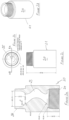
- FIGS 1a - I1 these illustrate a first embodiment of an insert, generally referenced 10.
- the insert is intended to be formed of a plastics material, although other materials suitable and known in the art can be utilised.
- the insert has a cylindrical body 11 of diameter 47mm and height 42.81mm, which in use is inserted into the hose of a blast machine.
- a flange 12, of thickness 3.88mm and diameter 63.5mm, at a first end of the cylindrical body 11, prevents the insert from being pushed too far into the hose and also facilitates the removal of an insert when not required or for replacement.
- the second end of the cylindrical body 11 has a chamfered surface 14 to facilitate insertion into the hose.
- the insert 10 is utilised such that the flow of fluid within the hose is from the first end towards the second end of the cylindrical body 11.
- the internal volume of the cylindrical body 11 is primarily solid, with a helical passage 13 of diameter 32mm is formed within the cylindrical body 11 which passage 13 acts to alter the fluid flow.
- Helical configurations and formations are known in the art and are believed to have primarily a rifling effect on the flow.
- the use of the phenomenon in blasting is confined it is believed to 1 phase systems.
- the positioning and the characteristics of the helix are here however such as to unexpectedly improve the performance.
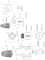
- insert 20 shown in Figures 2a - 2d again has a cylindrical body 21 in which a helical passage 23 is formed.
- a first end of the insert 20 has a first, internal, thread 24 and at the second end a second, external, thread 26.
- the threads 24, 26 allow for connection to a holder (described below) which is inserted into the hose.
- the diameter of the cylindrical body 21 can be chosen to suit the task but diameters of from 46 - 52 mm have been found to be suitable.
- the helical passage 23 is so formed as to provide a cylindrical channel 25 through from the first to the second ends of the insert 20.
- the insert 20 is intended in this embodiment to be utilised to link to an exit pipe of 31.75mm diameter. It has been found that the size of this channel and the offset of the channel axis from the main cylindrical axis of the cylindrical body has an important effect on the cleaning characteristics. In the exemplified second embodiment, 4 values for each of these parameters were chosen. In a first experiment a channel diameter of 10mm and an offset of 4.5mm were chosen. In a second experiment, a channel diameter of 7.5mm and an offset of 5.75mm were chosen.
- a channel diameter of 5mm and an offset of 7mm were chosen and in a fourth experiment, a channel diameter of 2.5mm and an offset of 8.25mm were chosen.
- cleaning experiments of removing a coating from a surface it was found that the third experiment yielded improved cleaning compared to the other experiments and that the second experiment, yielded improved cleaning over the first experiment.
- the structure of the insert 30 is as for the above second embodiment in that screw threads 31, 32 are provided for attachment to a holder inserted into a hose.
- the body 33 is increased in thickness in one region 34 to accommodate the machine to which the insert 30 is to be attached.
- two versions were provided in which in the first version, a channel diameter of 0.26" and offset of 0.12" were provided and a second version in which a channel diameter of 0.2" and an offset of 0.15" were provided.
- a fourth embodiment of insert is disclosed.
- the insert 40 is similar to that shown in Figures 1 , but includes a frusto-conical section 41 interposed between the flange 42 and the cylindrical body 43.
- the frusto-conical section 41 facilitates insertion of the insert 40 into a hose.
- the frusto-conical section 41 due to the resilient nature of the plastics material from which the insert is formed, frictionally engages the hose into which it is inserted and acts to prevent the insert 40 from spinning during use.
- a groove notch arrangement can be utilised to prevent spinning from occurring.
- the fourth embodiment includes a channel of non-constant width.
- the diameter of the helical channel 45 at the location indicated at 46 is 19mm.
- the channel has a diameter of 9mm. The narrowing of the helical passage 45 again affects the flow of fluid along the hose into which the air flows from the outlet 47, providing acceleration to the air-flow and reducing energy loss.
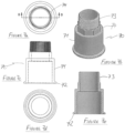
- FIGS 5a - 5f illustrate a fifth embodiment of insert 50.
- the internal helical structure of the insert 50 is as for the previous embodiments. Externally however, this embodiment includes an externally deployed screw-thread 51 to enable the fitment into a hose or into a holder as described below.
- the sixth embodiment of insert 60 shown in Figures 6a - 6c has an internal helical structure as described for the above embodiments. Externally however, this embodiment includes an externally deployed structure comprising nested frusto-conical sections 61 which facilitate the insert 60 being pushed into a hose, but act to resist the removal of the insert so that the insert 60 does not fall out of the hose during use.
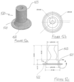
- a seventh embodiment of insert 120 is disclosed.
- the seventh embodiment includes, as does the fourth embodiment, a frusto-conical section 121 interposed between the flange 122 and the cylindrical body 123.
- the channel in this embodiment has a constant diameter of 19mm along its length.
- Figures 7a - 7e illustrate an insert holder for use, particularly in conjunction with a first embodiment of insert, for example shown in Figures 1 .
- the use of a holder facilitates attachment and removal of an insert, to for example replace a worn insert or to change inserts to provide a different flow pattern.
- a holder also acts to prevent an insert from spinning about its axis during use.
- Figures 7 has a generally cylindrical hollow body 71 to receive an insert.
- the flange 72 acts as a stop to prevent the insert from being pushed too far into the holder 70 and aids in correct alignment of the insert.
- Extending from one end of the cylindrical body 71 is a connector 73 having an outer thread.
- the connector 73 enables the holder 70 to be screwed into position within a conduit and the holder is profiled to a hexagonal form 74 to facilitate attachment using conventional tools.
- Figures 8a -8f illustrate a second embodiment of a holder 80.
- the holder 80 has a generally cylindrical hollow body 81 to receive an insert and a flange 82 to aid in correct alignment of the insert.
- the cylindrical body 81 has a plurality of throughapertures 83 in regular array about the circumference of the cylindrical body 81.
- the series of nested frusto-conical sections 84 provide a fitment means as for the previous embodiment.
- connection piece 90 of Figures 9a - 9d has a fitment means 91 formed of frusto-conical sections 91 as for the abovedescribed holder 80.
- the body of the connection piece 90 is however shorter than in the embodiment of Figures 8 and can be utilised where no return regulator is present in a compressor as shown in Figure 11 .
- the holder 100 of Figures 10 combines features from the abovedescribed embodiments.
- the holder 100 has a cylindrical hollow body 101 having a plurality of throughapertures 102 in regular array about the circumference of the body 101. Extending from one end of the cylindrical body 101 is a connector 103 having an outer thread 104.
- the connector 103 enables the holder 100 to be screwed into position within a conduit and the holder is profiled to a hexagonal form 105 to facilitate attachment using conventional tools.
- Figure 11 illustrates the process of fitting an insert 110 into position when using a compressor having a return regulator (upper row of illustration) and when no return regulator is present (lower row).
- the holder 80 In the upper row the holder 80 is push-fit into a free end of a blast hose.
- An insert 110 is inserted into the holder 80 as shown by the arrow A.
- a connection piece 90 is inserted into a further section of a hose in fluid connection with a compressor supplying pressurised fluid.
- the connection piece 90 and the holder 80 are then connected together co-operating to retain the insert 110 aligned in the correct position.
- a holder 100 as described in relation to Figures 10 is secured to the end of a hose by means of the screw-thread 104.
- the insert 110 is inserted into the holder 100 as shown by the arrow B.
- the fluid connection to the compressor is then secured to the free end of the insert 110.
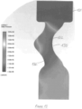
- FIG 13 illustrates the pressure within a flow stream having an insert 130 within the flow stream.
- the pressure is a uniform 6 bar.
- the pressure drops in the region 132.
- the pressure drops again.
- the velocity rises as it enters the insert at 141 and also stratifies around the middle of the helical flow path 142.
- the current invention acts to improve energy usage in that, although a shock wave takes place it takes place outside the nozzle and often after the fluid flow has impacted the surface to be cleaned.
- the fluid therefore has higher momentum at the point of impact than would be the case without the insert. This action is facilitated by the relatively short length of the insert in which the circular flow about the insert axis is generated in a short period of time.
Landscapes
- Engineering & Computer Science (AREA)
- Mechanical Engineering (AREA)
- Physics & Mathematics (AREA)
- Fluid Mechanics (AREA)
- General Engineering & Computer Science (AREA)
- Quick-Acting Or Multi-Walled Pipe Joints (AREA)
- Cleaning In General (AREA)
- Joints That Cut Off Fluids, And Hose Joints (AREA)
- Injection Moulding Of Plastics Or The Like (AREA)
- Rigid Pipes And Flexible Pipes (AREA)
- Nozzles (AREA)
Applications Claiming Priority (3)
| Application Number | Priority Date | Filing Date | Title |
|---|---|---|---|
| US202063085329P | 2020-09-30 | 2020-09-30 | |
| PCT/IB2021/059005 WO2022070133A1 (en) | 2020-09-30 | 2021-09-30 | An insert for use in dry blasting |
| EP21801622.8A EP4221899A1 (de) | 2020-09-30 | 2021-09-30 | Einsatz zur verwendung beim trockenstrahlen |
Related Parent Applications (1)
| Application Number | Title | Priority Date | Filing Date |
|---|---|---|---|
| EP21801622.8A Division EP4221899A1 (de) | 2020-09-30 | 2021-09-30 | Einsatz zur verwendung beim trockenstrahlen |
Publications (2)
| Publication Number | Publication Date |
|---|---|
| EP4570432A2 true EP4570432A2 (de) | 2025-06-18 |
| EP4570432A3 EP4570432A3 (de) | 2025-09-10 |
Family
ID=78483418
Family Applications (2)
| Application Number | Title | Priority Date | Filing Date |
|---|---|---|---|
| EP21801622.8A Withdrawn EP4221899A1 (de) | 2020-09-30 | 2021-09-30 | Einsatz zur verwendung beim trockenstrahlen |
| EP25167474.3A Pending EP4570432A3 (de) | 2020-09-30 | 2021-09-30 | Einsatz zur verwendung beim trockenstrahlen |
Family Applications Before (1)
| Application Number | Title | Priority Date | Filing Date |
|---|---|---|---|
| EP21801622.8A Withdrawn EP4221899A1 (de) | 2020-09-30 | 2021-09-30 | Einsatz zur verwendung beim trockenstrahlen |
Country Status (10)
| Country | Link |
|---|---|
| US (1) | US20230364741A1 (de) |
| EP (2) | EP4221899A1 (de) |
| JP (1) | JP2023545685A (de) |
| KR (1) | KR20230095965A (de) |
| CN (1) | CN116981517A (de) |
| AU (1) | AU2021354968A1 (de) |
| CA (1) | CA3194014A1 (de) |
| CL (1) | CL2023000863A1 (de) |
| MX (1) | MX2023003710A (de) |
| WO (1) | WO2022070133A1 (de) |
Family Cites Families (11)
| Publication number | Priority date | Publication date | Assignee | Title |
|---|---|---|---|---|
| US1966368A (en) * | 1932-06-13 | 1934-07-10 | Wil Bro Corp | Hose coupling and method of using the same |
| GB1603090A (en) * | 1978-05-25 | 1981-11-18 | Hughes & Co | Jetting apparatus |
| AU8025082A (en) * | 1981-02-06 | 1982-08-12 | Eaton Corporation | Swageable hose fitting |
| EP0633417B1 (de) * | 1993-07-05 | 1998-01-14 | J.M. Voith GmbH | Vorrichtung und Verfahren zur Drosselung einer Stoffsuspensionsströmung einer Papiermaschine |
| GB0822949D0 (en) * | 2008-12-16 | 2009-01-21 | Heliswirl Technologies Ltd | Pipe liner |
| IT1401044B1 (it) * | 2010-07-15 | 2013-07-12 | Ibix Srl | Pistola ad aria. |
| ES2536848T3 (es) * | 2010-11-12 | 2015-05-29 | Dental Care Innovation Gmbh | Sistema de limpieza dental |
| WO2014188223A1 (en) * | 2013-05-24 | 2014-11-27 | Nigel Richard Farrow | Improvement to material flow |
| CN107695895B (zh) * | 2017-11-22 | 2024-01-05 | 河南理工大学 | 一种利用旋转磨料射流减少喷嘴磨损的装置及方法 |
| CN108188939A (zh) * | 2017-12-25 | 2018-06-22 | 宁波高新区若水智创科技有限公司 | 一种高速旋转水砂切割喷头 |
| KR102148996B1 (ko) * | 2018-10-17 | 2020-08-28 | 한국철도기술연구원 | 구조물 내부 파우더 제거 장치 |
-
2021
- 2021-09-30 EP EP21801622.8A patent/EP4221899A1/de not_active Withdrawn
- 2021-09-30 JP JP2023520023A patent/JP2023545685A/ja active Pending
- 2021-09-30 CA CA3194014A patent/CA3194014A1/en active Pending
- 2021-09-30 WO PCT/IB2021/059005 patent/WO2022070133A1/en not_active Ceased
- 2021-09-30 CN CN202180076043.6A patent/CN116981517A/zh active Pending
- 2021-09-30 AU AU2021354968A patent/AU2021354968A1/en active Pending
- 2021-09-30 EP EP25167474.3A patent/EP4570432A3/de active Pending
- 2021-09-30 MX MX2023003710A patent/MX2023003710A/es unknown
- 2021-09-30 KR KR1020237014642A patent/KR20230095965A/ko active Pending
- 2021-09-30 US US18/029,310 patent/US20230364741A1/en active Pending
-
2023
- 2023-03-24 CL CL2023000863A patent/CL2023000863A1/es unknown
Also Published As
| Publication number | Publication date |
|---|---|
| US20230364741A1 (en) | 2023-11-16 |
| EP4221899A1 (de) | 2023-08-09 |
| KR20230095965A (ko) | 2023-06-29 |
| EP4570432A3 (de) | 2025-09-10 |
| CL2023000863A1 (es) | 2024-05-17 |
| WO2022070133A1 (en) | 2022-04-07 |
| AU2021354968A1 (en) | 2023-06-08 |
| MX2023003710A (es) | 2023-04-21 |
| JP2023545685A (ja) | 2023-10-31 |
| CA3194014A1 (en) | 2022-04-07 |
| CN116981517A (zh) | 2023-10-31 |
Similar Documents
| Publication | Publication Date | Title |
|---|---|---|
| EP0532697B1 (de) | Ellbogensystem mit laminarer strömung | |
| US10302104B2 (en) | Helix amplifier fittings | |
| EP3004708B1 (de) | Verbesserung an einem materialstrom | |
| KR101073842B1 (ko) | 배관내 녹이나 스케일 등 이물질 제거장치 | |
| US20180297050A1 (en) | Nozzle Apparatus | |
| US20210402335A1 (en) | Filter | |
| KR101862888B1 (ko) | 에어 건 | |
| US20210071692A1 (en) | Helix amplifier fittings | |
| EP4221899A1 (de) | Einsatz zur verwendung beim trockenstrahlen | |
| CA2474863A1 (en) | Method for loosening and fragmenting scale from the inside of pipes | |
| RU2355462C2 (ru) | Способ осуществления прямоточной сепарации газовых потоков от твердых и жидких примесей | |
| EP0104610B1 (de) | Vorschub einer Rohrschlange durch eine Rohrleitung mit Kurven | |
| US7090568B2 (en) | Blasting device | |
| Alboudawarej et al. | New design improves performance of gas-pipeline drip separators | |
| JPH05185044A (ja) | 管路内の油性物質排除方法 |
Legal Events
| Date | Code | Title | Description |
|---|---|---|---|
| PUAI | Public reference made under article 153(3) epc to a published international application that has entered the european phase |
Free format text: ORIGINAL CODE: 0009012 |
|
| STAA | Information on the status of an ep patent application or granted ep patent |
Free format text: STATUS: THE APPLICATION HAS BEEN PUBLISHED |
|
| AC | Divisional application: reference to earlier application |
Ref document number: 4221899 Country of ref document: EP Kind code of ref document: P |
|
| AK | Designated contracting states |
Kind code of ref document: A2 Designated state(s): AL AT BE BG CH CY CZ DE DK EE ES FI FR GB GR HR HU IE IS IT LI LT LU LV MC MK MT NL NO PL PT RO RS SE SI SK SM TR |
|
| REG | Reference to a national code |
Ref country code: DE Ref legal event code: R079 Free format text: PREVIOUS MAIN CLASS: B24C0005020000 Ipc: B05B0001340000 |
|
| RAP3 | Party data changed (applicant data changed or rights of an application transferred) |
Owner name: FARROW HOLDINGS GROUP, INC |
|
| PUAL | Search report despatched |
Free format text: ORIGINAL CODE: 0009013 |
|
| AK | Designated contracting states |
Kind code of ref document: A3 Designated state(s): AL AT BE BG CH CY CZ DE DK EE ES FI FR GB GR HR HU IE IS IT LI LT LU LV MC MK MT NL NO PL PT RO RS SE SI SK SM TR |
|
| RIC1 | Information provided on ipc code assigned before grant |
Ipc: B05B 1/34 20060101AFI20250801BHEP Ipc: F15D 1/02 20060101ALI20250801BHEP Ipc: B24C 7/00 20060101ALN20250801BHEP Ipc: B05B 7/14 20060101ALN20250801BHEP Ipc: B24C 5/02 20060101ALN20250801BHEP |
|
| RIN1 | Information on inventor provided before grant (corrected) |
Inventor name: FARROW, NIGEL RICHARD |
|
| RIN1 | Information on inventor provided before grant (corrected) |
Inventor name: FARROW, NIGEL RICHARD |
|
| STAA | Information on the status of an ep patent application or granted ep patent |
Free format text: STATUS: REQUEST FOR EXAMINATION WAS MADE |
|
| 17P | Request for examination filed |
Effective date: 20260310 |