EP0532589B1 - Lit fluidise avec lampes infrarouges immergees - Google Patents
Lit fluidise avec lampes infrarouges immergees Download PDFInfo
- Publication number
- EP0532589B1 EP0532589B1 EP91910746A EP91910746A EP0532589B1 EP 0532589 B1 EP0532589 B1 EP 0532589B1 EP 91910746 A EP91910746 A EP 91910746A EP 91910746 A EP91910746 A EP 91910746A EP 0532589 B1 EP0532589 B1 EP 0532589B1
- Authority
- EP
- European Patent Office
- Prior art keywords
- lamps
- bed
- disposed
- conduits
- volume
- Prior art date
- Legal status (The legal status is an assumption and is not a legal conclusion. Google has not performed a legal analysis and makes no representation as to the accuracy of the status listed.)
- Expired - Lifetime
Links
Images


Classifications
-
- F—MECHANICAL ENGINEERING; LIGHTING; HEATING; WEAPONS; BLASTING
- F27—FURNACES; KILNS; OVENS; RETORTS
- F27B—FURNACES, KILNS, OVENS, OR RETORTS IN GENERAL; OPEN SINTERING OR LIKE APPARATUS
- F27B15/00—Fluidised-bed furnaces; Other furnaces using or treating finely-divided materials in dispersion
- F27B15/02—Details, accessories, or equipment peculiar to furnaces of these types
- F27B15/14—Arrangements of heating devices
-
- B—PERFORMING OPERATIONS; TRANSPORTING
- B01—PHYSICAL OR CHEMICAL PROCESSES OR APPARATUS IN GENERAL
- B01J—CHEMICAL OR PHYSICAL PROCESSES, e.g. CATALYSIS OR COLLOID CHEMISTRY; THEIR RELEVANT APPARATUS
- B01J8/00—Chemical or physical processes in general, conducted in the presence of fluids and solid particles; Apparatus for such processes
- B01J8/18—Chemical or physical processes in general, conducted in the presence of fluids and solid particles; Apparatus for such processes with fluidised particles
- B01J8/24—Chemical or physical processes in general, conducted in the presence of fluids and solid particles; Apparatus for such processes with fluidised particles according to "fluidised-bed" technique
- B01J8/42—Chemical or physical processes in general, conducted in the presence of fluids and solid particles; Apparatus for such processes with fluidised particles according to "fluidised-bed" technique with fluidised bed subjected to electric current or to radiations this sub-group includes the fluidised bed subjected to electric or magnetic fields
-
- C—CHEMISTRY; METALLURGY
- C21—METALLURGY OF IRON
- C21D—MODIFYING THE PHYSICAL STRUCTURE OF FERROUS METALS; GENERAL DEVICES FOR HEAT TREATMENT OF FERROUS OR NON-FERROUS METALS OR ALLOYS; MAKING METAL MALLEABLE, e.g. BY DECARBURISATION OR TEMPERING
- C21D1/00—General methods or devices for heat treatment, e.g. annealing, hardening, quenching or tempering
- C21D1/34—Methods of heating
- C21D1/53—Heating in fluidised beds
-
- H—ELECTRICITY
- H05—ELECTRIC TECHNIQUES NOT OTHERWISE PROVIDED FOR
- H05B—ELECTRIC HEATING; ELECTRIC LIGHT SOURCES NOT OTHERWISE PROVIDED FOR; CIRCUIT ARRANGEMENTS FOR ELECTRIC LIGHT SOURCES, IN GENERAL
- H05B3/00—Ohmic-resistance heating
- H05B3/0033—Heating devices using lamps
- H05B3/0038—Heating devices using lamps for industrial applications
Definitions
- This invention pertains to improvements in the controlled heat treating of products. More particularly, this invention pertains to a fluidized bed heat treatment apparatus with infrared radiation heating sources.
- furnaces for heat treating a product.
- Such furnaces generate an extremely hot bed of fluidizing particles such as aluminum oxide.
- the furnaces can be used for both continuous processing of a product or batch processing of products.
- U.S. Patent No. 4,752,061 (of which the present inventor is a co-inventor) teaches a fluidized bed furnace which uses infrared radiation as the heating source.
- infrared radiation as the heating source is that it permits the use of inert gases to fluidize the particles in the furnace. As a result, a controlled atmosphere can be provided surrounding the product being heat treated in the furnace.
- an apparatus for heat treating a product comprises a bed of fluidizing particles for use in said heat treatment; volume defining means for defining a volume sized to receive said bed of fluidizing particles with said bed selected to exceed a pre-determined elevation within said volume; a plurality of horizontally disposed electrically powered infra-red radiation lamps; and mounting means for mounting said plurality of lamps within said volume beneath said pre-determined elevation; said mounting means including horizontally disposed conduits disposed within said volume beneath said elevation, a said lamp disposed within a said conduit, said conduits formed of material generally transparent to infra-red radiation.
- an apparatus for heat treating a product comprises a bed of fluidizing particles for use in said heat treatment; a retort having walls for defining a volume; said bed of fluidizing particles disposed within said volume; a plurality of electrically powered infra-red radiation lamps; mounting means for mounting said plurality of said lamps submerged within said bed; said mounting means including conduits disposed submerged within said bed, a said lamp disposed within a said conduit, said conduits formed of material generally transparent to infra-red radiation.
- the furnace 10 includes a retort 12, which is preferably formed of R330 stainless steel or the like.
- the retort 12 includes a bottom wall 14, end walls 15, 16 and side walls 17, 18. Walls 14 - 18 cooperate to define a retort interior 20.
- a cover (not shown in the Figures) may be provided to cover the top of the retort 12.
- the furnace 10 also includes an outer shell 22 shown best in Figs. 5 and 6.
- Outer shell 22 includes a first outer shell wall 24 covering wall 17, and a second outer shell wall 26 covering wall 18.
- a central portion of shell wall 24 has been removed to expose wall 17.
- Wall 24 and wall 17 cooperate to define an exhaust plenum 28.
- Walls 26 and 18 cooperate to define an inlet plenum 30.
- interior divider walls 31 and 32 are provided within the interior 20.
- Walls 31, 32 extend between side walls 17 and 18 and are parallel to end walls 15 and 16.
- the divider walls 31, 32 extend from floor 14 partially toward the top of the retort 12.
- Walls 31, 32 divide retort interior 20 into a fluidizing chamber 20a, a first overflow chamber 20b, and a second overflow chamber 20c (see Fig. 4).
- a plurality of quartz tubes 36 are plurality extending between and through walls 17 and 18. As shown, the tubes 36 are disposed in parallel alignment, generally perpendicular to side walls 17, 18 and parallel to the floor 14 of the retort 12. The tubes 36 are disposed within the fluidizing portion 20a of interior 20, and are located beneath a predetermined elevation 38 (see Fig. 4) of fluidizing particles to be retained within the chamber 20a.
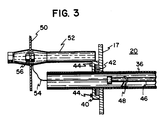
- Fig. 3 shows attachment of the tube 36 to side wall 17.
- the quartz tube 36 is similarly attached to side wall 18.
- the tube 36 extends through side wall 17, and is connected to the side wall 17 by a steel mounting clamp 40.
- the clamp 40 houses a plurality of ceramic washers 42.
- the clamp 40 is attached to side wall 17 by bolts 44.
- An infrared lamp 46 is disposed within each of tubes 36, as best shown in Figs. 2, 3, 5 and 6, (for clarity, lamps are not shown within the tubes 36 in Figs. 1 and 4).
- the lamp 46 is completely contained between walls 17, 18, and is retained in coaxial alignment within tube 36 by a mounting clip 48.
- bus bar plates 50 are provided. (For clarity bus bar plates are not shown in Figs. 1 and 4.) As shown in Fig. 2, nine bus bar plates are provided for each side 17, 18 of the retort 12. In the schematic representation of Fig. 6, eight bus bar plates are shown on each side.
- the bus bar plates 50 are electrically conductive plates of metal. Each plate 50 is connected to a separately controllable source (not shown) of electrical power to energize the plate 50.
- the plates 50 are secured to the walls 17, 18 by bus bar plate mounts 52 (see Fig. 3), which are preferably ceramic.
- a lead 54 connects the infrared lamp 46 to the bus bar plate 50.
- the lead 54 is connected to the bus bar plate 50 by a nut and bolt combination 56.
- a plurality of lamps 46 are covered by any given bus bar plate 50.
- each of the bus bar plates 50 is removed from covering the lamps 46 and tubes 36.
- the positioning of the bus bar plates 50 over the lamps 46 in Fig. 2 is shown in phantom lines.
- the length of the fluidizing chamber 20a can be divided into a plurality of zones.
- Each bus bar plate 50 with its associated lamps 46 constitutes a given zone.
- the intensity of the lamps connected to each bus bar plate 50 can be separately controlled. As a result, a temperature gradient can be created across the length of the chamber 20a.
- a stainless steel screen 60 is placed above the lamps 46 and quartz tubes 36.
- the screen 60 prevents a product that is being heat treated from falling onto the quartz tubes 36 and possibly damaging them.
- Fluidizing tubes 62 are provided disposed between the floor 14 and the quartz tubes 36.
- the tubes 62 are connected via conduit 64 to a source (not shown) of a fluidizing gas.
- the fluidizing gas may be air or any inert gas such as nitrogen.
- the fluidizing tubes 62 may be such as those shown and described in U.S. Patent No. 4,752,061 and indicated by reference numerals 98 in Fig. of that patent.
- a coolant mechanism is provided to pass a cooling fluid (preferably air) through the tubes 36 to cool the infrared lamps 46.
- a blower 70 is provided connected to inlet plenum 30.
- An exhaust fan (not shown) may be connected through an exhaust conduit 72 to exhaust plenum 28. As a result, cooling air may be forced from plenum 30 through each of tubes 36 into plenum 28 and out exhaust conduit 72.
- a bed of fluidizing particles (preferably granular aluminum oxide) is provided within the retort 12.
- a first layer 80 of coarse particle (preferably of 12 grit size) is provided covering the fluidizing tubes 62 and terminating beneath the quartz tubes 36.
- Finer aluminum oxide sand (preferably of 100 grit size) rests on top of the coarser sand 80, and terminates at level 38. The coarser sand 80 diffuses the fluidizing gas from the fluidizing tubes 62, and distributes it evenly to the quartz tubes 36.
- the infrared lamps 46 may heat from 0°-4000°F.
- the aluminum oxide will heat from 0°-2100°F.
- a controller 100 (schematically shown in Fig. 2) is connected through control lines 102 to each of bus plates 50. Through operation of controller 100, the potential on each of bus plates 50 may be separately controlled. Accordingly, the plurality of infrared lamps 46 are divided into a plurality of separately controllable zones.
- the lamps 46 heat the aluminum oxide.
- the fluidizing gas from tubes 62 fluidizes the aluminum oxide.
- the divider walls 31, 32 capture within chambers 20b and 20c any aluminum oxide which spills out of the fluidizing chamber 20a.
Abstract
Claims (9)
- Appareil de traitement thermique d'un produit, cet appareil comportant un lit de particules fluidisantes (80) pour utilisation dans ledit traitement thermique ;
des moyens de définition du volume (12), chargés de définir un volume dimensionné de manière à pouvoir recevoir ledit lit de particules fluidisantes (80), ledit lit étant choisi de manière à dépasser une hauteur prédéfinie (38) à l'intérieur dudit volume ;
une multiplicité de lampes à rayonnement infrarouge (46) disposées horizontalement et à alimentation électrique ; et
des moyens de montage (36) permettant de monter ladite multiplicité de lampes (46) à l'intérieur dudit volume au-dessous de ladite hauteur prédéfinie (38) ;
lesdits moyens de montage (36) incluant des conduites disposées à l'horizontale (36) et placées à l'intérieur dudit volume au-dessous de ladite hauteur (38), ladite lampe (46) étant installée à l'intérieur de ladite conduite (36), lesdites conduites (36) étant en un matériau généralement transparent au rayonnement infrarouge. - Appareil conçu pour le traitement thermique d'un produit qui comporte un lit de particules fluidisantes (8) pour utilisation dans ledit traitement thermique ;
une cornue (12) comportant des parois (14, 15, 16, 17, 18) afin de définir un volume ;
ledit lit de particules fluidisantes (80) étant disposé dans ledit volume ;
une multiplicité de lampes à rayonnement infrarouge (46) alimentées en électricité ;
des moyens de montage (36) permettant de monter ladite multiplicité desdites lampes (46), immergées dans ledit lit (80) ;
lesdits moyens de montage comprenant des conduites disposées dans ledit lit, de manière à être immergées, ladite lampe étant disposée dans ladite conduite, lesdites conduites étant en un matériau généralement transparent au rayonnement infrarouge. - Appareil selon les revendications 1 ou 2, comportant des moyens d'admission du gaz pour l'admission d'un gaz fluidisant dans ledit volume placé au-dessous desdites lampes (46).
- Appareil selon l'une quelconque des revendications précédentes, et dans lequel lesdits moyens de montage comportent une multiplicité de conduites (36) disposées dans ledit lit (80) où elles sont immergées, avec au moins l'une des lampes (46) qui est placée à l'intérieur de chacune desdites conduites (36).
- Appareil selon la revendication 4, dans lequel lesdites conduites (36) sont disposées les unes par rapport aux autres de manière à ce qu'un lit fluidisé (80) puisse s'écouler autour desdites conduites (36), et entre celles-ci.
- Appareil selon l'une quelconque des revendications précédentes, dans laquelle ladite conduite (36) est en quartz.
- Appareil selon l'une quelconque des revendications précédentes, dans lequel ladite multiplicité de lampes à rayonnement infrarouge (46) alimentées en courant électrique sont divisées en une multiplicité de zones pouvant être contrôlées séparément, chacun de celles-ci contenant au moins une lampe à rayonnement infrarouge (46).
- Appareil selon l'une quelconque des revendications précédentes, dans lequel lesdites conduites (36) et lesdites lampes (46) sont dimensionnées les unes et les autres afin que les surfaces desdites lampes (46) et desdites conduites (36) qui sont placées face à face puissent définir une multiplicité de passages permettant à l'air de s'écouler et entourant lesdites lampes (46), et des moyens de refroidissement (70) conçus pour fournir un flux de liquide réfrigérant auxdits passages.
- Appareil selon l'une quelconque des revendications précédentes, dans lequel ledit lit comprend au moins deux couches, dont une première couche (80) de particules grossières et une seconde couche de particules fines, ladite couche grossière (80) étant placée en-dessous desdites lampes (46).
Applications Claiming Priority (3)
| Application Number | Priority Date | Filing Date | Title |
|---|---|---|---|
| US53546890A | 1990-06-08 | 1990-06-08 | |
| US535468 | 1990-06-08 | ||
| PCT/US1991/004105 WO1991019148A1 (fr) | 1990-06-08 | 1991-06-07 | Lit fluidise avec lampes infrarouges immergees |
Publications (2)
| Publication Number | Publication Date |
|---|---|
| EP0532589A1 EP0532589A1 (fr) | 1993-03-24 |
| EP0532589B1 true EP0532589B1 (fr) | 1994-10-26 |
Family
ID=24134372
Family Applications (1)
| Application Number | Title | Priority Date | Filing Date |
|---|---|---|---|
| EP91910746A Expired - Lifetime EP0532589B1 (fr) | 1990-06-08 | 1991-06-07 | Lit fluidise avec lampes infrarouges immergees |
Country Status (6)
| Country | Link |
|---|---|
| US (1) | US5294095A (fr) |
| EP (1) | EP0532589B1 (fr) |
| AU (1) | AU648091B2 (fr) |
| CA (1) | CA2085365C (fr) |
| DE (1) | DE69104833D1 (fr) |
| WO (1) | WO1991019148A1 (fr) |
Families Citing this family (8)
| Publication number | Priority date | Publication date | Assignee | Title |
|---|---|---|---|---|
| US5189813A (en) * | 1991-02-22 | 1993-03-02 | Samuel Strapping Systems Ltd. | Fluidized bed and method of processing material |
| CA2053394A1 (fr) * | 1991-10-11 | 1993-04-12 | James E. Heath | Elements chauffants emettant des radiations et structure |
| US5490517A (en) * | 1994-04-12 | 1996-02-13 | The United States Of America As Represented By The Secretary Of The Navy | Occupant reach and mobility apparatus |
| US5893217A (en) * | 1997-10-28 | 1999-04-13 | Cat-Tec Industries, Inc. | Agitated bed infrared drying apparatus |
| US6042369A (en) * | 1998-03-26 | 2000-03-28 | Technomics, Inc. | Fluidized-bed heat-treatment process and apparatus for use in a manufacturing line |
| DE19940845C1 (de) * | 1999-08-27 | 2000-12-21 | Graf & Co Ag | Verfahren und Vorrichtung zum Herstellen von Feindraht |
| US20040081577A1 (en) * | 2002-10-29 | 2004-04-29 | Macaluso Virgil J. | Method of treating comestible material for disinfestation, enzyme denaturation and microorganism control |
| US20110083593A1 (en) * | 2009-10-12 | 2011-04-14 | AirClean Technologies, Inc. | Fluidized combustor |
Family Cites Families (22)
| Publication number | Priority date | Publication date | Assignee | Title |
|---|---|---|---|---|
| CA868257A (en) * | 1971-04-13 | R And I-Ramtite (Canada) Limited | Shell sand treating apparatus and method | |
| US3404874A (en) * | 1964-09-25 | 1968-10-08 | Lectromeit Corp | Vacuum furnace |
| US3546431A (en) * | 1969-04-25 | 1970-12-08 | Erich L Gibbs | Immersion heater and method of making the same |
| GB1293187A (en) * | 1969-11-24 | 1972-10-18 | Upper Canada Mfg Ltd | Improvements relating to the treatment of granular material |
| US3685165A (en) * | 1970-10-12 | 1972-08-22 | Combustion Eng | Thermal sand reclamation unit |
| JPS5641044A (en) * | 1979-09-10 | 1981-04-17 | Dependable Fordath Inc | Method of casting sheel mold |
| JPS5745335A (en) * | 1980-09-02 | 1982-03-15 | Mitsui Eng & Shipbuild Co Ltd | Heating fluidized bed reactor |
| EP0132493B1 (fr) * | 1980-12-16 | 1988-06-15 | Cosworth Research And Development Limited | Appareil et procédé pour la régénération de sable de fonderie usé |
| DE3103030C2 (de) * | 1981-01-30 | 1984-05-03 | Klöckner-Humboldt-Deutz AG, 5000 Köln | Verfahren zur Gewinnung von Gießereisand aus gebrauchtem Gießereisand |
| US4399984A (en) * | 1982-02-08 | 1983-08-23 | Midland-Ross Corporation | Automatic installation for the heat treatment of workpieces in fluidized beds |
| DE3242298A1 (de) * | 1982-11-16 | 1984-05-17 | Rivi Establishment, 9490 Vaduz | Verfahren und vorrichtung zum erhitzen von fluessigen medien |
| GB2137114B (en) * | 1983-03-09 | 1986-12-17 | Cosworth Res & Dev Ltd | Casting metal and reclaiming foundry sand |
| DE3400648A1 (de) * | 1984-01-11 | 1985-07-18 | Delta Engineering Beratung und Vermittlung Gesellschaft mbH, Irdning | Vorrichtung und verfahren zur regeneration von giesserei-schuttsand |
| AU576071B2 (en) * | 1985-02-22 | 1988-08-11 | Brian Harding | Sparge pipe assembly for fluidised bed |
| GB8511622D0 (en) * | 1985-05-08 | 1985-06-12 | Richards Structural Steel Co L | Thermal reclamation of industrial sand |
| DE3688422T2 (de) * | 1985-08-07 | 1993-08-26 | Samuel Strapping Systems Ltd | Beheizung eines fliessbettofens. |
| DE3622668C1 (en) * | 1986-07-05 | 1988-02-11 | Ewald Schwing | Fluidised bed kiln for the heat treatment of metallic objects |
| US4818849A (en) * | 1987-07-13 | 1989-04-04 | Matlen Abraham J | Shielded lamp unit |
| FR2618539B1 (fr) * | 1987-07-21 | 1989-09-22 | Electricite De France | Procede et dispositif de deshydratation a chauffage electrique |
| US4885454A (en) * | 1988-04-29 | 1989-12-05 | Centorr Associates, Inc. | High temperature furnace for oxidizing atmospheres |
| US4978076A (en) * | 1990-03-28 | 1990-12-18 | Gmd Engineered Systems, Inc. | Method for separating hazardous substances in waste foundry sands |
| US5189813A (en) * | 1991-02-22 | 1993-03-02 | Samuel Strapping Systems Ltd. | Fluidized bed and method of processing material |
-
1991
- 1991-06-07 AU AU80887/91A patent/AU648091B2/en not_active Ceased
- 1991-06-07 WO PCT/US1991/004105 patent/WO1991019148A1/fr active IP Right Grant
- 1991-06-07 DE DE69104833T patent/DE69104833D1/de not_active Expired - Lifetime
- 1991-06-07 CA CA002085365A patent/CA2085365C/fr not_active Expired - Fee Related
- 1991-06-07 EP EP91910746A patent/EP0532589B1/fr not_active Expired - Lifetime
-
1992
- 1992-08-03 US US07/924,399 patent/US5294095A/en not_active Expired - Fee Related
Also Published As
| Publication number | Publication date |
|---|---|
| US5294095A (en) | 1994-03-15 |
| AU648091B2 (en) | 1994-04-14 |
| EP0532589A1 (fr) | 1993-03-24 |
| AU8088791A (en) | 1991-12-31 |
| CA2085365C (fr) | 1996-03-12 |
| CA2085365A1 (fr) | 1991-12-09 |
| WO1991019148A1 (fr) | 1991-12-12 |
| DE69104833D1 (de) | 1994-12-01 |
Similar Documents
| Publication | Publication Date | Title |
|---|---|---|
| US5340089A (en) | Coolant controlled IR heat treat apparatus | |
| EP0224320B1 (fr) | Chauffage de four à lit fluidisé | |
| US6437292B1 (en) | Rapid infrared heating of a surface | |
| EP0532589B1 (fr) | Lit fluidise avec lampes infrarouges immergees | |
| JPH05506299A (ja) | 高い強さの赤外線熱処理装置 | |
| WO1988007096A3 (fr) | Installation d'application de couches epitaxiales | |
| US4665626A (en) | Process and device for drying of coated work pieces through infrared radiation | |
| US4327665A (en) | Method and apparatus for coating composition on can seams | |
| US5332139A (en) | Fluidized bed apparatus and method using same | |
| WO1992006780A1 (fr) | Appareil de thermotraitement par rayonnement infrarouge modulable a l'aide d'un refrigerant | |
| US3841240A (en) | Continuous fluid bed wire burn-off apparatus and method | |
| US3686034A (en) | Gravity flow sand reclamation process | |
| EP0553243B1 (fr) | Appareil a lit fluidise et procede d'utilisation | |
| US5202080A (en) | Fluidized bed apparatus | |
| CN114535742A (zh) | 真空系统的操作方法和真空系统 | |
| EP0572460B1 (fr) | Lit fluidifie et procede de traitement de materiaux | |
| JPH03194923A (ja) | 熱処理炉 | |
| JPS60117082A (ja) | 金属および非金属物体を流動床処理する装置 | |
| SU918733A1 (ru) | Способ тепломассообмена | |
| CA1236291A (fr) | Four a lit fluidise chauffant aux infrarouges | |
| US2973192A (en) | Apparatus for rapid heating of one side only of work | |
| JPS6284290A (ja) | 流動層炉における加熱装置及び方法 | |
| JPS6415330A (en) | Bluing treatment of steel products | |
| CA2080858A1 (fr) | Elements chauffants a rayonnement et construction | |
| WO1993006920A1 (fr) | Elements de chauffage radiants ameliores et structure |
Legal Events
| Date | Code | Title | Description |
|---|---|---|---|
| PUAI | Public reference made under article 153(3) epc to a published international application that has entered the european phase |
Free format text: ORIGINAL CODE: 0009012 |
|
| AK | Designated contracting states |
Kind code of ref document: A1 Designated state(s): DE ES FR GB SE |
|
| 17P | Request for examination filed |
Effective date: 19930107 |
|
| 17Q | First examination report despatched |
Effective date: 19931227 |
|
| GRAA | (expected) grant |
Free format text: ORIGINAL CODE: 0009210 |
|
| AK | Designated contracting states |
Kind code of ref document: B1 Designated state(s): DE ES FR GB SE |
|
| PG25 | Lapsed in a contracting state [announced via postgrant information from national office to epo] |
Ref country code: ES Free format text: THE PATENT HAS BEEN ANNULLED BY A DECISION OF A NATIONAL AUTHORITY Effective date: 19941026 |
|
| REF | Corresponds to: |
Ref document number: 69104833 Country of ref document: DE Date of ref document: 19941201 |
|
| ET | Fr: translation filed | ||
| PG25 | Lapsed in a contracting state [announced via postgrant information from national office to epo] |
Ref country code: SE Effective date: 19950126 |
|
| PG25 | Lapsed in a contracting state [announced via postgrant information from national office to epo] |
Ref country code: DE Effective date: 19950127 |
|
| PLBE | No opposition filed within time limit |
Free format text: ORIGINAL CODE: 0009261 |
|
| STAA | Information on the status of an ep patent application or granted ep patent |
Free format text: STATUS: NO OPPOSITION FILED WITHIN TIME LIMIT |
|
| 26N | No opposition filed | ||
| PGFP | Annual fee paid to national office [announced via postgrant information from national office to epo] |
Ref country code: FR Payment date: 19960515 Year of fee payment: 6 |
|
| PGFP | Annual fee paid to national office [announced via postgrant information from national office to epo] |
Ref country code: GB Payment date: 19960529 Year of fee payment: 6 |
|
| PG25 | Lapsed in a contracting state [announced via postgrant information from national office to epo] |
Ref country code: GB Free format text: LAPSE BECAUSE OF NON-PAYMENT OF DUE FEES Effective date: 19970607 |
|
| GBPC | Gb: european patent ceased through non-payment of renewal fee |
Effective date: 19970607 |
|
| PG25 | Lapsed in a contracting state [announced via postgrant information from national office to epo] |
Ref country code: FR Free format text: LAPSE BECAUSE OF NON-PAYMENT OF DUE FEES Effective date: 19980227 |
|
| REG | Reference to a national code |
Ref country code: FR Ref legal event code: ST |
|
| REG | Reference to a national code |
Ref country code: FR Ref legal event code: ST |