EP0531536A1 - Method of molding preform having inner walls and synthetic resin vessel having inner walls - Google Patents
Method of molding preform having inner walls and synthetic resin vessel having inner walls Download PDFInfo
- Publication number
- EP0531536A1 EP0531536A1 EP92904405A EP92904405A EP0531536A1 EP 0531536 A1 EP0531536 A1 EP 0531536A1 EP 92904405 A EP92904405 A EP 92904405A EP 92904405 A EP92904405 A EP 92904405A EP 0531536 A1 EP0531536 A1 EP 0531536A1
- Authority
- EP
- European Patent Office
- Prior art keywords
- partition wall
- internal partition
- preform
- wall
- thickness
- Prior art date
- Legal status (The legal status is an assumption and is not a legal conclusion. Google has not performed a legal analysis and makes no representation as to the accuracy of the status listed.)
- Granted
Links
Images


Classifications
-
- B—PERFORMING OPERATIONS; TRANSPORTING
- B65—CONVEYING; PACKING; STORING; HANDLING THIN OR FILAMENTARY MATERIAL
- B65D—CONTAINERS FOR STORAGE OR TRANSPORT OF ARTICLES OR MATERIALS, e.g. BAGS, BARRELS, BOTTLES, BOXES, CANS, CARTONS, CRATES, DRUMS, JARS, TANKS, HOPPERS, FORWARDING CONTAINERS; ACCESSORIES, CLOSURES, OR FITTINGS THEREFOR; PACKAGING ELEMENTS; PACKAGES
- B65D1/00—Containers having bodies formed in one piece, e.g. by casting metallic material, by moulding plastics, by blowing vitreous material, by throwing ceramic material, by moulding pulped fibrous material, by deep-drawing operations performed on sheet material
- B65D1/02—Bottles or similar containers with necks or like restricted apertures, designed for pouring contents
- B65D1/04—Multi-cavity bottles
-
- B—PERFORMING OPERATIONS; TRANSPORTING
- B29—WORKING OF PLASTICS; WORKING OF SUBSTANCES IN A PLASTIC STATE IN GENERAL
- B29B—PREPARATION OR PRETREATMENT OF THE MATERIAL TO BE SHAPED; MAKING GRANULES OR PREFORMS; RECOVERY OF PLASTICS OR OTHER CONSTITUENTS OF WASTE MATERIAL CONTAINING PLASTICS
- B29B11/00—Making preforms
- B29B11/06—Making preforms by moulding the material
- B29B11/08—Injection moulding
-
- B—PERFORMING OPERATIONS; TRANSPORTING
- B29—WORKING OF PLASTICS; WORKING OF SUBSTANCES IN A PLASTIC STATE IN GENERAL
- B29B—PREPARATION OR PRETREATMENT OF THE MATERIAL TO BE SHAPED; MAKING GRANULES OR PREFORMS; RECOVERY OF PLASTICS OR OTHER CONSTITUENTS OF WASTE MATERIAL CONTAINING PLASTICS
- B29B11/00—Making preforms
- B29B11/14—Making preforms characterised by structure or composition
-
- B—PERFORMING OPERATIONS; TRANSPORTING
- B29—WORKING OF PLASTICS; WORKING OF SUBSTANCES IN A PLASTIC STATE IN GENERAL
- B29C—SHAPING OR JOINING OF PLASTICS; SHAPING OF MATERIAL IN A PLASTIC STATE, NOT OTHERWISE PROVIDED FOR; AFTER-TREATMENT OF THE SHAPED PRODUCTS, e.g. REPAIRING
- B29C49/00—Blow-moulding, i.e. blowing a preform or parison to a desired shape within a mould; Apparatus therefor
- B29C49/071—Preforms or parisons characterised by their configuration, e.g. geometry, dimensions or physical properties
-
- B—PERFORMING OPERATIONS; TRANSPORTING
- B29—WORKING OF PLASTICS; WORKING OF SUBSTANCES IN A PLASTIC STATE IN GENERAL
- B29C—SHAPING OR JOINING OF PLASTICS; SHAPING OF MATERIAL IN A PLASTIC STATE, NOT OTHERWISE PROVIDED FOR; AFTER-TREATMENT OF THE SHAPED PRODUCTS, e.g. REPAIRING
- B29C49/00—Blow-moulding, i.e. blowing a preform or parison to a desired shape within a mould; Apparatus therefor
- B29C49/08—Biaxial stretching during blow-moulding
- B29C49/10—Biaxial stretching during blow-moulding using mechanical means for prestretching
- B29C49/12—Stretching rods
-
- B—PERFORMING OPERATIONS; TRANSPORTING
- B29—WORKING OF PLASTICS; WORKING OF SUBSTANCES IN A PLASTIC STATE IN GENERAL
- B29C—SHAPING OR JOINING OF PLASTICS; SHAPING OF MATERIAL IN A PLASTIC STATE, NOT OTHERWISE PROVIDED FOR; AFTER-TREATMENT OF THE SHAPED PRODUCTS, e.g. REPAIRING
- B29C49/00—Blow-moulding, i.e. blowing a preform or parison to a desired shape within a mould; Apparatus therefor
- B29C49/42—Component parts, details or accessories; Auxiliary operations
- B29C49/64—Heating or cooling preforms, parisons or blown articles
- B29C49/6409—Thermal conditioning of preforms
- B29C49/6463—Thermal conditioning of preforms by contact heating or cooling, e.g. mandrels or cores specially adapted for heating or cooling preforms
-
- B—PERFORMING OPERATIONS; TRANSPORTING
- B29—WORKING OF PLASTICS; WORKING OF SUBSTANCES IN A PLASTIC STATE IN GENERAL
- B29C—SHAPING OR JOINING OF PLASTICS; SHAPING OF MATERIAL IN A PLASTIC STATE, NOT OTHERWISE PROVIDED FOR; AFTER-TREATMENT OF THE SHAPED PRODUCTS, e.g. REPAIRING
- B29C2949/00—Indexing scheme relating to blow-moulding
- B29C2949/07—Preforms or parisons characterised by their configuration
- B29C2949/0715—Preforms or parisons characterised by their configuration the preform having one end closed
-
- B—PERFORMING OPERATIONS; TRANSPORTING
- B29—WORKING OF PLASTICS; WORKING OF SUBSTANCES IN A PLASTIC STATE IN GENERAL
- B29C—SHAPING OR JOINING OF PLASTICS; SHAPING OF MATERIAL IN A PLASTIC STATE, NOT OTHERWISE PROVIDED FOR; AFTER-TREATMENT OF THE SHAPED PRODUCTS, e.g. REPAIRING
- B29C2949/00—Indexing scheme relating to blow-moulding
- B29C2949/07—Preforms or parisons characterised by their configuration
- B29C2949/072—Preforms or parisons characterised by their configuration having variable wall thickness
-
- B—PERFORMING OPERATIONS; TRANSPORTING
- B29—WORKING OF PLASTICS; WORKING OF SUBSTANCES IN A PLASTIC STATE IN GENERAL
- B29C—SHAPING OR JOINING OF PLASTICS; SHAPING OF MATERIAL IN A PLASTIC STATE, NOT OTHERWISE PROVIDED FOR; AFTER-TREATMENT OF THE SHAPED PRODUCTS, e.g. REPAIRING
- B29C2949/00—Indexing scheme relating to blow-moulding
- B29C2949/07—Preforms or parisons characterised by their configuration
- B29C2949/073—Preforms or parisons characterised by their configuration having variable diameter
- B29C2949/0733—Preforms or parisons characterised by their configuration having variable diameter at body portion
-
- B—PERFORMING OPERATIONS; TRANSPORTING
- B29—WORKING OF PLASTICS; WORKING OF SUBSTANCES IN A PLASTIC STATE IN GENERAL
- B29C—SHAPING OR JOINING OF PLASTICS; SHAPING OF MATERIAL IN A PLASTIC STATE, NOT OTHERWISE PROVIDED FOR; AFTER-TREATMENT OF THE SHAPED PRODUCTS, e.g. REPAIRING
- B29C2949/00—Indexing scheme relating to blow-moulding
- B29C2949/07—Preforms or parisons characterised by their configuration
- B29C2949/074—Preforms or parisons characterised by their configuration having ribs or protrusions
-
- B—PERFORMING OPERATIONS; TRANSPORTING
- B29—WORKING OF PLASTICS; WORKING OF SUBSTANCES IN A PLASTIC STATE IN GENERAL
- B29C—SHAPING OR JOINING OF PLASTICS; SHAPING OF MATERIAL IN A PLASTIC STATE, NOT OTHERWISE PROVIDED FOR; AFTER-TREATMENT OF THE SHAPED PRODUCTS, e.g. REPAIRING
- B29C2949/00—Indexing scheme relating to blow-moulding
- B29C2949/07—Preforms or parisons characterised by their configuration
- B29C2949/075—Preforms or parisons characterised by their configuration having at least one internal separating wall
- B29C2949/0751—Preforms or parisons characterised by their configuration having at least one internal separating wall at neck portion
-
- B—PERFORMING OPERATIONS; TRANSPORTING
- B29—WORKING OF PLASTICS; WORKING OF SUBSTANCES IN A PLASTIC STATE IN GENERAL
- B29C—SHAPING OR JOINING OF PLASTICS; SHAPING OF MATERIAL IN A PLASTIC STATE, NOT OTHERWISE PROVIDED FOR; AFTER-TREATMENT OF THE SHAPED PRODUCTS, e.g. REPAIRING
- B29C2949/00—Indexing scheme relating to blow-moulding
- B29C2949/07—Preforms or parisons characterised by their configuration
- B29C2949/075—Preforms or parisons characterised by their configuration having at least one internal separating wall
- B29C2949/0753—Preforms or parisons characterised by their configuration having at least one internal separating wall at body portion
-
- B—PERFORMING OPERATIONS; TRANSPORTING
- B29—WORKING OF PLASTICS; WORKING OF SUBSTANCES IN A PLASTIC STATE IN GENERAL
- B29C—SHAPING OR JOINING OF PLASTICS; SHAPING OF MATERIAL IN A PLASTIC STATE, NOT OTHERWISE PROVIDED FOR; AFTER-TREATMENT OF THE SHAPED PRODUCTS, e.g. REPAIRING
- B29C2949/00—Indexing scheme relating to blow-moulding
- B29C2949/07—Preforms or parisons characterised by their configuration
- B29C2949/075—Preforms or parisons characterised by their configuration having at least one internal separating wall
- B29C2949/0754—Preforms or parisons characterised by their configuration having at least one internal separating wall at bottom portion
-
- B—PERFORMING OPERATIONS; TRANSPORTING
- B29—WORKING OF PLASTICS; WORKING OF SUBSTANCES IN A PLASTIC STATE IN GENERAL
- B29C—SHAPING OR JOINING OF PLASTICS; SHAPING OF MATERIAL IN A PLASTIC STATE, NOT OTHERWISE PROVIDED FOR; AFTER-TREATMENT OF THE SHAPED PRODUCTS, e.g. REPAIRING
- B29C2949/00—Indexing scheme relating to blow-moulding
- B29C2949/07—Preforms or parisons characterised by their configuration
- B29C2949/076—Preforms or parisons characterised by their configuration characterised by the shape
- B29C2949/0768—Preforms or parisons characterised by their configuration characterised by the shape characterised by the shape of specific parts of preform
- B29C2949/077—Preforms or parisons characterised by their configuration characterised by the shape characterised by the shape of specific parts of preform characterised by the neck
- B29C2949/0771—Wide-mouth
-
- B—PERFORMING OPERATIONS; TRANSPORTING
- B29—WORKING OF PLASTICS; WORKING OF SUBSTANCES IN A PLASTIC STATE IN GENERAL
- B29C—SHAPING OR JOINING OF PLASTICS; SHAPING OF MATERIAL IN A PLASTIC STATE, NOT OTHERWISE PROVIDED FOR; AFTER-TREATMENT OF THE SHAPED PRODUCTS, e.g. REPAIRING
- B29C2949/00—Indexing scheme relating to blow-moulding
- B29C2949/07—Preforms or parisons characterised by their configuration
- B29C2949/076—Preforms or parisons characterised by their configuration characterised by the shape
- B29C2949/0768—Preforms or parisons characterised by their configuration characterised by the shape characterised by the shape of specific parts of preform
- B29C2949/077—Preforms or parisons characterised by their configuration characterised by the shape characterised by the shape of specific parts of preform characterised by the neck
- B29C2949/0772—Closure retaining means
- B29C2949/0773—Threads
-
- B—PERFORMING OPERATIONS; TRANSPORTING
- B29—WORKING OF PLASTICS; WORKING OF SUBSTANCES IN A PLASTIC STATE IN GENERAL
- B29C—SHAPING OR JOINING OF PLASTICS; SHAPING OF MATERIAL IN A PLASTIC STATE, NOT OTHERWISE PROVIDED FOR; AFTER-TREATMENT OF THE SHAPED PRODUCTS, e.g. REPAIRING
- B29C2949/00—Indexing scheme relating to blow-moulding
- B29C2949/20—Preforms or parisons whereby a specific part is made of only one component, e.g. only one layer
- B29C2949/22—Preforms or parisons whereby a specific part is made of only one component, e.g. only one layer at neck portion
-
- B—PERFORMING OPERATIONS; TRANSPORTING
- B29—WORKING OF PLASTICS; WORKING OF SUBSTANCES IN A PLASTIC STATE IN GENERAL
- B29C—SHAPING OR JOINING OF PLASTICS; SHAPING OF MATERIAL IN A PLASTIC STATE, NOT OTHERWISE PROVIDED FOR; AFTER-TREATMENT OF THE SHAPED PRODUCTS, e.g. REPAIRING
- B29C2949/00—Indexing scheme relating to blow-moulding
- B29C2949/20—Preforms or parisons whereby a specific part is made of only one component, e.g. only one layer
- B29C2949/24—Preforms or parisons whereby a specific part is made of only one component, e.g. only one layer at flange portion
-
- B—PERFORMING OPERATIONS; TRANSPORTING
- B29—WORKING OF PLASTICS; WORKING OF SUBSTANCES IN A PLASTIC STATE IN GENERAL
- B29C—SHAPING OR JOINING OF PLASTICS; SHAPING OF MATERIAL IN A PLASTIC STATE, NOT OTHERWISE PROVIDED FOR; AFTER-TREATMENT OF THE SHAPED PRODUCTS, e.g. REPAIRING
- B29C2949/00—Indexing scheme relating to blow-moulding
- B29C2949/20—Preforms or parisons whereby a specific part is made of only one component, e.g. only one layer
- B29C2949/26—Preforms or parisons whereby a specific part is made of only one component, e.g. only one layer at body portion
-
- B—PERFORMING OPERATIONS; TRANSPORTING
- B29—WORKING OF PLASTICS; WORKING OF SUBSTANCES IN A PLASTIC STATE IN GENERAL
- B29C—SHAPING OR JOINING OF PLASTICS; SHAPING OF MATERIAL IN A PLASTIC STATE, NOT OTHERWISE PROVIDED FOR; AFTER-TREATMENT OF THE SHAPED PRODUCTS, e.g. REPAIRING
- B29C2949/00—Indexing scheme relating to blow-moulding
- B29C2949/20—Preforms or parisons whereby a specific part is made of only one component, e.g. only one layer
- B29C2949/28—Preforms or parisons whereby a specific part is made of only one component, e.g. only one layer at bottom portion
-
- B—PERFORMING OPERATIONS; TRANSPORTING
- B29—WORKING OF PLASTICS; WORKING OF SUBSTANCES IN A PLASTIC STATE IN GENERAL
- B29C—SHAPING OR JOINING OF PLASTICS; SHAPING OF MATERIAL IN A PLASTIC STATE, NOT OTHERWISE PROVIDED FOR; AFTER-TREATMENT OF THE SHAPED PRODUCTS, e.g. REPAIRING
- B29C49/00—Blow-moulding, i.e. blowing a preform or parison to a desired shape within a mould; Apparatus therefor
- B29C49/02—Combined blow-moulding and manufacture of the preform or the parison
- B29C49/06—Injection blow-moulding
-
- B—PERFORMING OPERATIONS; TRANSPORTING
- B29—WORKING OF PLASTICS; WORKING OF SUBSTANCES IN A PLASTIC STATE IN GENERAL
- B29C—SHAPING OR JOINING OF PLASTICS; SHAPING OF MATERIAL IN A PLASTIC STATE, NOT OTHERWISE PROVIDED FOR; AFTER-TREATMENT OF THE SHAPED PRODUCTS, e.g. REPAIRING
- B29C49/00—Blow-moulding, i.e. blowing a preform or parison to a desired shape within a mould; Apparatus therefor
- B29C49/08—Biaxial stretching during blow-moulding
- B29C49/10—Biaxial stretching during blow-moulding using mechanical means for prestretching
- B29C49/12—Stretching rods
- B29C49/1206—Stretching rods using at least two stretching rods for stretching different parts of the preform
-
- B—PERFORMING OPERATIONS; TRANSPORTING
- B29—WORKING OF PLASTICS; WORKING OF SUBSTANCES IN A PLASTIC STATE IN GENERAL
- B29C—SHAPING OR JOINING OF PLASTICS; SHAPING OF MATERIAL IN A PLASTIC STATE, NOT OTHERWISE PROVIDED FOR; AFTER-TREATMENT OF THE SHAPED PRODUCTS, e.g. REPAIRING
- B29C49/00—Blow-moulding, i.e. blowing a preform or parison to a desired shape within a mould; Apparatus therefor
- B29C49/08—Biaxial stretching during blow-moulding
- B29C49/10—Biaxial stretching during blow-moulding using mechanical means for prestretching
- B29C49/122—Drive means therefor
- B29C49/123—Electric drives, e.g. linear motors
Landscapes
- Engineering & Computer Science (AREA)
- Mechanical Engineering (AREA)
- Manufacturing & Machinery (AREA)
- Physics & Mathematics (AREA)
- Ceramic Engineering (AREA)
- Thermal Sciences (AREA)
- Geometry (AREA)
- Blow-Moulding Or Thermoforming Of Plastics Or The Like (AREA)
Abstract

Description
- The present invention relates to a preform usable in molding a plastic vessel having an internal partition wall which is capable of resisting an internal pressure from a filled matter, and a process of making such a plastic vessel.
- When a preform is biaxially oriented, it is known in the art to provide a plastic vessel which has an open top portion as part of the preform, a cylindrical barrel portion formed below the top portion and having an internal diameter larger than that of the top portion, a shoulder portion connecting between the top and barrel portions, and a bottom portion formed to close the barrel portion at the end remote from the top portion. Many plastic vessels molded by the prior art generally have increased degrees of stretching in longitudinal and transverse axes and circular cross-sections in their barrel portions. In such plastic vessels, the internal stress from the internal pressure can be uniformly dispersed through the barrel portion in its circumferential direction since the barrel portion is of circular cross-section. Further, any distortion of the barrel portion due to the internal pressure from such as carbon dioxide gas can be fully prevented by the mechanical strength of the barrel portion which has been increased by crystallization from the biaxial orientation.
- In case when a plastic vessel has its barrel portion of triangular or square cross-section or of oval crosssection, however, the internal pressure will concentrate on only a part of the side barrel wall, resulting in distortion of the side barrel wall which is weaker in mechanical strength.
- In a further case of so-called wide-mouthed type plastic vessels in which the difference of internal diameter between the top and barrel portions in a plastic vessel is relatively small, such plastic vessels are inferior in mechanical strength even if they are biaxially oriented for crystallization, because the ratio of transverse stretch is small. Even if a widemouthed type plastic vessel is of circular cross-section, it is probably impossible to prevent certainly the distortion in the barrel portion of such a plastic vessel due to the internal pressure from the contents therein.
- A proposal for increasing a wide-mouthed type plastic vessel in its mechanical strength is made in WO90/05674 which discloses a bottle comprising an internal spider which extends across the interior of the bottle and is biaxially oriented with the side wall of the bottle.
- In the biaxial-stretch blow molding process for such a bottle, the smoothness of its biaxially stretching operation for a preform is obstructed by the presence of the internal spider, unlike the prior art biaxial orientation for cylindrical preforms. Since the internal spider is connected at one end to the inner side wall of the preform, that portion of inner side wall which is connected to the internal spider substantially resists the biaxial stretching step. It has been found that when the preform has been molded into a bottle, the outer side wall of the bottle tends to have a recess formed therein at that portion of the bottle which is connected to the internal spider. Such a recess will very damage the external appearance of the produced bottle.
- In course of the inventors' study, it has been found that it is very difficult to form such an internal spider into a substantially uniform wall thickness when a bottle is molded. Unlike the conventional process for biaxially stretching only the side wall of the preform, the portions of the spider extending in various directions resist to each other on stretching such that the preform will be prevented from being stretched into a uniform wall thickness. In addition, it has been found that when the preform is stretched by a stretching rod along the longitudinal axis and by a blown air in the transverse direction within each of the partitions divided by the internal spider, the internal spider will be bias stretched in a particular orientation.
- It was thus difficult that an actually usable bottle having its internal spider could be molded without various improvements.
- It is therefore an object of the present invention to provide a preform which is optimum in molding a plastic vessel having an internal partition wall.
- Another object of the present invention is to provide a process of molding a plastic vessel having an internal partition wall without damage to the external appearance thereof.
- To this end, the present invention provides a preform to be biaxially stretched and blow molded into a plastic vessel, said preform comprising an open top portion, a cylindrical barrel portion, a bottom portion formed to close the barrel portion at the end opposite to the open top and an internal partition wall formed within said barrel portion to extend from one side to the other side of the inner wall and to extend longitudinally from the bottom portion, said preform being characterized by that said internal partition wall has a thickness profile in the transverse direction relative to the longitudinal axis of the preform in which the wall thickness is maximum at the connection between the internal partition wall and the inner wall of the barrel portion the wall thickness of the internal partition wall is gradually reduced toward the longitudinal center axis of the preform.
- The portion of the internal partition wall having the increased wall thickness adjacent to the inner wall of the barrel portion can be more easily stretched since it has an increased thermal capacity. Thus, the internal partition wall can be fully stretched following the biaxially stretching of the barrel portion at the increased wall thickness of the internal partition wall. The central portion of the internal partition wall is subjected to a relatively weak stretching force and inherently less stretched. Therefore, if the wall thickness of the internal partition wall is set to be relatively thin at and near the central portion thereof and also to be gradually increased toward the outer portion of the internal partition wall having the maximum wall thickness, the internal partition wall can be smoothly stretched in the transverse direction to have a substantially uniform wall thickness after stretched. The wall thickness of the internal partition wall at and near the central portion thereof may be substantially uniform through an extent in the transverse direction.
- It is preferred that the internal partition wall also has a thickness profile in the longitudinal direction of the preform, in which the wall thickness is maximum at the connection between the internal partition wall and the bottom portion, the wall thickness of the internal partition wall is gradually reduced toward the top of the internal partition wall. This is advantageous in that the step of regulating the temperature of the preform do not necessarily require a complicated distribution of temperature in the direction of the longitudinal axis. It may be secured that the internal partition wall of the preform is stretched into a uniform wall thickness even along the longitudinal axis.
- In order to prevent any distortion due to the internal pressure, the top end of the internal partition wall may be formed short of the open top portion of the preform within the barrel portion. It is preferred that the top end portion of the internal partition wall near the longitudinal center axis of the preform is lower than the top end portion of the internal partition wall near the connection between the internal partition wall and the inner barrel wall. This is because such an arrangement can facilitate the stretching near the center of the internal partition wall.
- The internal partition wall may be extended to the open top portion of the preform and preferably to the top edge thereof. In such a case, that portion of the internal partition wall located within the top portion must have a wall thickness smaller than the minimum wall thickness of the internal partition wall within the barrel portion of the preform. Thus, the portion of the internal partition wall located within the top portion is not easily stretched so that the sealing configuration of the top edge can be retained even after the preform has been blow molded into a desired vessel. If a cap is mounted on such a vessel, the inner bottom face of the cap co-operates with the internal partition wall to provide a plurality of separately divided partitions.
- The present invention also provides a process of biaxial-stretch blow molding a plastic vessel, said process being characterized by the steps of injection molding a preform having an open top portion, a cylindrical barrel portion having a closed bottom, and an internal partition wall formed to extend from one side of the inner wall of the barrel portion to the other side of the same and to extend longitudinally from the inner face of the closed bottom, stretchedly driving said bottom portion along the longitudinal axis of said preform by the use of a plurality of stretching rods each arranged for the respective one of partitions divided by the internal partition wall of said preform while at the same time stretching said preform in the transverse direction by introducing a pressurized air into the respective divided partitions, the inner end of each of said stretching rods including a tip member arranged therein at a position offset toward the longitudinal center axis of said preform than the center of the corresponding partition, whereby said internal partition wall can be guided by said tip members when said preform is being stretched along the longitudinal axis thereof.
- In accordance with the present invention, the stretching is carried out by the stretching rod and blown air in each of the partitions of the preform which are separately divided by the internal partition wall. If a stretching rod is positioned substantially at the center of each of the partitions, a deviation out of the longitudinal center axis tends to be created near the longitudinal center axis which is the central junction in the internal partition wall, due to a slight deviation for the rod's position, a difference between the internal pressures of the respective partitions, a temperature dispersion and so on. In order to overcome such a problem, each of the tip members is positioned within the respective one of the separately divided partitions at a position offset toward the longitudinal center axis of the preform. Thus, the internal partition wall can be stretched directly along the longitudinal axis of the preform.
- Fig. 1 is a schematic view, partially broken, of a plastic vessel having an internal partition wall.
- Fig. 2 is a plane view of the vessel shown in Fig. 1.
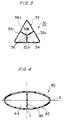
- Fig. 3 is a schematic cross-section of a vessel of triangular cross-section having an internal partition wall.
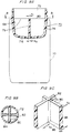
- Fig. 4 is a schematic cross-section of a vessel of oval cross-section having an internal partition wall.
- Fig. 5 is a schematic longitudinal-section of a vessel having an internal partition wall which is flat at the top edge thereof.
- Fig. 6 is a schematic longitudinal-section of a vessel having an internal partition wall which is extended to the same level as the top edge of the top portion of the vessel.
- Fig. 7 is a schematic longitudinal-section of a vessel having an internal partition wall which is formed to have such a height that the top portion of the vessel can be air-tightly sealed by an internal cap.
- Fig. 8A is a schematic longitudinal-section of a modified top configuration of the internal partition wall.
- Fig. 8B is a cross-sectional view of the vessel taken along a line A-A in Fig. 8A.
- Fig. 9A is a schematic longitudinal-section of a preform molded into the vessel shown in Fig. 1.
- Fig. 9B is a cross-sectional view of the preform taken along a line B-B in Fig. 9A.
- Fig. 9C is a perspective view of the internal partition wall shown in Fig. 9A.
- Fig. 10 is a schematic longitudinal-section of an injection molding device for injection molding a preform.
- Fig. 11 is a schematic longitudinal-section of a blow molding device for biaxially stretching and blow molding the preform into a vessel.
- Fig. 12 is a schematic cross-section of the blow molding device shown in Fig. 11, illustrating the plane arrangement of the stretching rods and air ducts.
- Fig. 13 is a cross-sectional view of a preform usable to mold the vessel shown in Fig. 4.
- Fig. 14 is a longitudinal-sectional view of a preform usable to mold the vessel shown in Fig. 6.
- Fig. 15 is a cross-sectional view of a modified preform usable to mold the vessel shown in Fig. 1.
- Fig. 16 is a schematic longitudinal-section of a distribution of uniform wall thickness areas shown in Fig. 15.
- Fig. 17 is a schematic longitudinal-section of the preform shown in Fig. 16, illustrating a step of regulating the temperature of the preform.
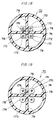
- Figs. 18 and 19 respectively illustrate the arrangements of stretching rods and tip members which are offset toward the longitudinal center axis of the preform.
- Fig. 20 is a schematic longitudinal-section of a preform usable to mold the vessel shown in Fig. 8.
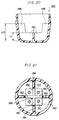
- Figs. 21 and 22 are schematic views respectively illustrating the arrangements of stretching rods and tip members which are usable in the preform shown in Fig. 20.
- Fig. 23 is a schematic longitudinal-section of a preform which is being biaxially stretched and blow molded by the use of the stretching rods shown in Figs. 21 and 22.
- The present invention will now be described in detail mainly with reference to some embodiments of the present invention which are applied to the molding of vessels having square cross-sections and made of polyethylene terephthalate (which will be called simply "PET").
- Referring to Figs. 1 and 2, a
vessel 10 comprises an opentop portion 12 which has an opening having its internal diameter (a) and a threadedportion 12a formed around the outer peripheral wall of the opentop portion 12, acylindrical barrel portion 14 of square cross-section having an internal diameter (b) larger than the internal diameter (a) of the opentop portion 12, acurved shoulder portion 16 smoothly connecting between the open top andbarrel portions bottom portion 18 closing thebarrel portion 14 at the end remote from the opentop portion 12. - The
vessel 10 also comprises aninternal partition wall 20 formed therewithin, which extend from the inner wall of thebottom portion 18 toward thetop portion 12. Theinternal partition wall 20 includes four partition portions which are respectively connected to theinner side walls 14a - 14d of the square-shapedbarrel portion 14 at therespective connections 22 and which intersect each other at thecenter 24 of theinternal partition wall 20 to form a cross-shaped cross-sectional configuration. - In this embodiment, the
top edge 20a of theinternal partition wall 20 is positioned at the upper part of thebarrel portion 14 short of the opentop portion 12 that is, at a position near the lower part of theshoulder portion 16. Thetop edge 20a of theinternal partition wall 20 is formed to have the maximum level at the saidconnections 22 and the minimum level at thecenter 24 of theinternal partition wall 20. The maximum and minimum level portions are connected to each other by a curved configuration having a continuously varying height. - In case of the
vessel 10 of such a square cross-section as shown in Fig. 2, theinternal partition wall 20 has aconnection 22 on the respective one of the fourside walls 14a - 14d at its intermediate location and four partition portions which intersect each other at thecenter 24 of theinternal partition wall 20 and extend directly from innerbottom connecting portion 26. Thus, each of theside walls 14a - 14d of thebarrel portion 14 and thebottom portion 18 are connected with one another through the cross-shapedinternal partition wall 20 to provide a substantially improved mechanical strength in theside walls 14a - 14d andbottom portion 18. - The provision of such an
internal partition wall 20 can not only increase the mechanical strength in theside walls 14a - 14d, but also reduce the total internal pressure acting on each of theside walls 14a - 14d. In other words, the internal pressure acting on each of theside walls 14a - 14d can be reduced by the total internal pressure acting on theinternal partition wall 20, thus being capable of preventing thebarrel portion 14 from being distorted by the internal pressure in the vessel. - The variation of the top edge of the
internal partition wall 20 from the maximum height at theside connection 22 to the minimum height at thecenter 24 as shown in Fig. 1 can best facilitate the molding thereof. - Fig. 3 shows a
vessel 30 of triangle cross-section to which the present invention is applied. Thevessel 30 comprises aninternal partition wall 36 formed therein which includes three partition portions extending longitudinally from thebottom portion 34 and also radially from thecenter 38b to therespective side walls 32a - 32c, each partition portion being connected to the intermediate location of the corresponding one of the threeside walls 32a - 32c at theconnection 38a. The angular spacing between each pair of adjacent side walls is equal to 120 degrees. - Fig. 4 shows a
vessel 40 of oval cross-section which includes aninternal partition wall 46 longitudinally extending from thebottom portion 44 and connecting the side walls of thebarrel portion 42 opposed to each other in the direction of short axis Y. A plurality of suchinternal partition walls 46 may be provided parallel to the short axis Y to more reliably prevent thebarrel portion 42 from being distorted. - Figs. 5 and 6 show modifications with respect to the height of the
internal partition wall 20 shown in Fig. 1. In Fig. 5, thetop edge 20a of theinternal partition wall 20 extends perpendicular to the longitudinal axis thereof. Although theinternal partition walls 20 shown in Figs. 1 and 5 have their top edges terminating at the halfway position of thebarrel portion 14, thetop edge 20a of theinternal partition wall 20 may extend to the same level as thetop edge 12b of the opentop portion 12, as shown in Fig. 6. In such an arrangement as shown in Fig. 6, a cap mounted on thetop portion 12 will have its inner wall sealing between thetop edge 12b of thetop portion 12 and thetop edge 20a of theinternal partition wall 20. Thus, the partitions divided by the cross-shapedinternal partition wall 20 can be sealingly separated from one another and receive different types of contents such as teas, spices and candies without mixture. - Fig. 7 shows a modified embodiment having the same function as that of the embodiment shown in Fig. 6. In the embodiment of Fig. 7, the
top edge 20a of the openinternal partition wall 20 terminates at the midway level of the opentop portion 12 and also extends perpendicular to the longitudinal axis of theinternal partition wall 20. If anexternal cap 50 having aninternal cap 52 as made of plastic is threadedly mounted on thetop portion 12 of the vessel, thebottom face 52a of theinternal cap 52 can seal thetop edge 20a of theinternal partition wall 20. Thus, a vessel may be provided which can receive different types of contents in the respective partitions, as in the embodiment of Fig. 6. - Figs. 8A and 8B show a further modification of the
internal partition wall 20 shown in Fig. 1. Thevessel 10 comprises aninternal partition wall 60 of cross-shaped cross-section which includes a central wing portion having a relatively small height shown by H1 and four side wing portions having a substantially large height shown by H2. Theinternal partition wall 60 is connected at a connectingportion 67 to the inner wall of thebottom portion 18 and at a connectingportion 64 to therespective side walls 14a - 14d. - Such an
internal partition wall 60 can similarly provide a sufficient mechanical strength to thevessel 10 near thebottom portion 18 and at the fourside walls 14a - 14b. Thus, the barrel andbottom portions internal partition wall 60 is very low around the longitudinal center axis of thevessel 10 as shown by H1, the flow of content will be least disturbed by theinternal partition wall 60 when thevessel 10 is tilted for drinking or pouring-out. - One embodiment of a process of molding a vessel according to the present invention will be described with reference to Fig. 9.
- Fig. 9A shows a
preform 70 injection molded into an intermediate product which is usable to mold thevessel 10 shown in Fig. 1. Thepreform 70 comprises an opentop portion 72, abarrel portion 74 of circular cross-section connected to thetop portion 72 and abottom portion 76 formed to close thebarrel portion 74 at the end opposite to the open top, as in the prior art. Thepreform 70 further comprises aninternal partition wall 78 of cross-shaped cross-section connecting each pair of opposed inner side walls to each other and extending from thebottom portion 76 to a predetermined height in the direction of longitudinal axis. Thetop edge 80 of theinternal partition wall 78 extends perpendicular to the longitudinal axis thereof. It is desirable that the wall thickness of theinternal partition wall 78 is set to such sizes as shown in Figs. 9B and 9C at various locations thereof. If it is assumed that the wall thickness of theinternal partition wall 78 is a1 on thelongitudinal center axis 82 at thetop edge 80; a2 in each sidewall connecting end 84 at thetop edge 80; a3 on thelongitudinal center axis 82 at thebottom edge 86; and a4 in each sidewall connecting end 84 at thebottom edge 86, it is desirable that a1<a2<a3<a4. - The setting of the sizes of the
internal partition wall 78 at various locations is made from the viewpoint of providing aninternal partition wall 20 having a uniform wall thickness as a whole when thepreform 70 is molded into such avessel 10 as shown in Fig. 1. This will be described in more detail later. - Fig. 10 shows an injection molding device for the
preform 70, which comprises a top formingmold 90 for molding the opentop portion 72 of thepreform 70, aninjection cavity mold 92 for defining the outer walls of the barrel andbottom portions preform 70, and aninjection core mold 94 for defining the inner walls of the open top, the barrel andbottom portions internal partition wall 78. Theinjection cavity mold 92 includes acentral gate 96 formed therein at the bottom. Molten PET material is charged into abottom molding cavity 98,barrel molding cavity 100 andtop molding cavity 102 in theinjection cavity mold 92 through thegate 96. The molten PET material is also injected into thepartition molding cavity 104 of theinjection core mold 94. In such a manner, thepreform 70 will be injection molded. Theinjection core mold 94 includes coolingportions 106 through which a cooling medium is circulated to cool the resin material, each of the coolingportions 106 being located at a position corresponding to the respective one of four partitions to be divided by theinternal partition wall 78 of thepreform 70. - After injection molded the
preform 70, theinjection core mold 94 is first moved upwardly. Thepreform 70 is then removed from theinjection cavity mold 92 while thetop forming mold 90 holds thepreform 70. Thepreform 70 is then moved to a temperature regulating step (not shown) by the use of the top formingmold 90. At the temperature regulating step, thepreform 70 is heated to an optimum stretching temperature and then moved to a biaxial-stretch blow molding step shown in Fig. 11. - The biaxial-stretch blow molding step utilizes a split
blow cavity mold 110 having a mold cavity substantially in conformance with the outer walls of the barrel, shoulder and bottom portions (14, 16 and 18) of thevessel 10 shown in Fig. 1. Theblow cavity mold 110 includes a bottom mold 112 connected thereto at the open bottom and is also connected at the open top to a vertically movableblow core mold 114. On operation, after thepreform 70 is moved into the biaxial-stretch blow molding step by thetop forming mold 90, the bottom mold 112 is first moved vertically, and then the splitblow cavity mold 110 is closed. Thereafter, theblow core mold 114 is inserted into thetop portion 72 of thepreform 70 through the top formingmold 90. - The
blow core mold 114 is characterized by that in this embodiment, it comprises four stretchingrods 120 each located at a position corresponding to the respective one of four partitions separately divided by theinternal partition wall 78 of thepreform 70 and fourblow air ducts 122 each similarly located at a position corresponding to the respective partition aforementioned. The plane arrangement of these stretching rods and air ducts is as shown in Fig. 12. As will be apparent from Fig. 12, this embodiment includes the four stretchingrods 120 each of which is substantially centrally disposed within the corresponding partition. Each of the fourblow air ducts 122 includes anair discharge port 124 which is offset from the stretchingrod 120 in the same partition. - After the molds have been arranged as aforementioned, the four stretching
rods 120 are then moved downwardly to stretch thepreform 70 along the longitudinal axis thereof. At the same time, the pressurized air is blown into the respective partitions of thepreform 70 through theair discharge ports 124 of theblow air ducts 122 to stretch thepreform 70 in the transverse direction. If the four stretchingrods 120 are driven by the same drive, thepreform 70 can be longitudinally stretched at the same speed with respect to the respective partitions divided by theinternal partition wall 78. Moreover, if the pressurized air is introduced into the four partitions substantially with the same pressure level, thevessel 10 can be blow molded without distortion and uneven wall thickness in theinternal partition wall 20. - The aforementioned values a1 - a4 of wall thickness in the
internal partition wall 78 of thepreform 70 are set for the following reasons. - From experiments, the inventors have found that when the barrel and
bottom portions preform 70 are stretch blow molded in the longitudinal and transverse directions, the sidewall connecting edges 84 of theinternal partition wall 78 are more easily stretched than thecentral portion 82 thereof and also that thebottom connecting edge 86 of theinternal partition wall 78 is more easily stretched than thetop edge 80 thereof. It is believed that the sidewall connecting edges 84 of theinternal partition wall 78 are subjected to a stretching force higher than thecentral portion 82 since the sidewall connecting edges 84 follow thebarrel portion 74 being stretched. If the central andside portions internal partition wall 78 of thepreform 70 have the same wall thickness at the top edge 80 (a1 = a2), thevessel 10 will be biaxially stretch blow molded with thecentral portion 24 of theinternal partition wall 20 having its wall thickness larger than that of each of theside portions 22. This is apparently undesirable in that thevessel 10 has no uniform wall thickness throughout. If thevessel 10 is molded of a transparent resin material such as PET such an uneven wall thickness will very damage the external appearance of thevessel 10. - In addition, if the
internal partition wall 78 of thepreform 70 has a uniform wall thickness in the transverse direction, it will be difficult that theside portions 84 of theinternal partition wall 78 follow the side barrel wall being stretched since thecentral portion 82 of theinternal partition wall 78 is hardly stretched. This results in formation of undesirable recesses in the side wall of the bottle molded. - In order to overcome such problems, the values of wall thickness of the
preform 70 in the transverse direction are set to be a1<a2 and a3<a4. This permits theinternal partition wall 78 to follow the side wall being stretched since the sidewall connecting portion 84 has a larger wall thickness and retains a high temperature. Since on the other hand, thecentral portion 82 of thepreform 70 is subjected to a smaller stretching force, it has been previously set to have a smaller wall thickness. Thus, thevessel 10 will finally have an uniform wall thickness throughout since the final wall thickness of thecentral portion 82 becomes substantially equal to that of theside portion 84 more stretched. - Normally, the top and
bottom portions internal partition wall 78 in thepreform 70 have a draft angle in view of the release properties in theinjection core mold 94. It has been found that any irregularity in wall thickness providing the reduced wall thickness of thebottom portion 26 in theinternal partition wall 20 of the moldedvessel 10 cannot be overcome by a difference in wall thickness as being provided by such a draft angle. However, if the setting of wall thickness to be a1<a3 and a2<a4 is made to provide a differential size which is larger than the normal draft angle but suitably depends on the ratio of longitudinal stretch in thevessel 10, theinternal partition wall 20 of the moldedvessel 10 can have a substantially uniform wall thickness therethrough from the bottom to top ends. Since thepreform 70 more easily has a temperature profile distributed throughout along the longitudinal axis at the temperature regulating step, the aforementioned setting of wall thickness in theinternal partition wall 78 can be made only in the transverse direction. - From experiments, the inventors have found that the moldability can be improved by providing the downwardly curved
top edge 20a of theinternal partition wall 20 of thevessel 10 with theside portions 22 being higher than thecentral portion 24, as shown in Fig. 1. This is because thecentral portion 24 of theinternal partition wall 20 is more stretched by the four stretchingrods 120 in the longitudinal direction, resulting in the height of thecentral portion 24 to be lower than that of thetop edges 20a at the sidewall connecting portions 22. An amount of material saved by forming the curvedtop edge 20a of theinternal partition wall 20 serves to save the total amount of material necessary to mold thepreform 70. It has been also found that such a saving of material will not very reduce the mechanical strength in thebarrel portion 14 of thevessel 10, compared with the flattop edge 20a of theinternal partition wall 20 as shown in Fig. 5. Even in the arrangement of Fig. 1, the height of thetop edge 20a of theinternal partition wall 20 at the sidewall connecting portions 22 is substantially the same as that of the arrangement shown in Fig. 5. If the height of thetop edge 20a of theinternal partition wall 20 at the sidewall connecting portions 22 is ensured to be sufficient, the mechanical strength in thebarrel portion 14 from the bottom portion to that level can be secured to prevent thebarrel portion 14 from being distorted due to the internal pressure from the contents. - If it is desired to locate the
top edge 20a of theinternal partition wall 20 within the opentop portion 12 of thevessel 10 as shown in Figs. 6 and 7, the setting of wall thickness in theinternal partition wall 78 of thepreform 70 must be carefully made in consideration of the following respect: - The open
top portion 12 of the preform will not substantially be stretched during the biaxial-stretch blow molding process. Thus, that portion of theinternal partition wall 78 located within the opentop portion 72 of thepreform 70 must have its wall thickness as thin as possible in view of no stretching therein. - Various preform configurations usable to mold plastic vessels having internal partition walls will be described below.
- Fig. 13 shows a
preform 130 usable to mold the vessel shown in Fig. 4. Thepreform 130 has aninternal partition wall 134 extending across thebarrel portion 132 of circular cross-section from one side to the other and longitudinally from the bottom portion. The wall thickness of theinternal partition wall 134 is set at various locations to be a1<a2 and a1<a3<a4, as shown in Fig. 9C. - Fig. 14 shows a
preform 140 usable to mold the vessel of Fig. 6. Thepreform 140 has aninternal partition wall 148 extending longitudinally from abottom portion 146 to the same level as that of the top edge of an opentop portion 142. The internal partition wall portion 148a present in abarrel portion 144 has the maximum wall thickness a3 at anend portion 148c at which the internal partition wall is connected to thebottom portion 146, with the wall thickness of the internal partition wall portion 148a being gradually reduced toward the upper partition portion having its smaller wall thickness a1 located near the top end of thebarrel portion 144. It is preferred that the internalpartition wall portion 148b present in the opentop portion 142 has a wall thickness a0 equal to or smaller than the wall thickness a1 in thebarrel portion 144 of thepreform 140. This is for such a purpose that the internalpartition wall portion 148b in the opentop portion 142 is not substantially caused to be stretched. It is particularly preferred that the thinner internalpartition wall portion 148b in the opentop portion 142 has been previously regulated into a temperature lower than those of the remaining regions to be stretched at the temperature regulating step prior to the biaxial-stretch blow molding step. - In case where the top edge of the internal partition wall terminates at any level in the open
top portion 12 as in Fig. 7, the internal partition wall portion present in the open top portion of its preform may have a wall thickness set as in Fig. 14. - Fig. 15 shows a
preform 150 usable to mold the vessel of Fig. 1. Thepreform 150 has aninternal partition wall 154 extending across thebarrel portion 152 and having a cross-shaped cross-section. Theinternal partition wall 154 has fouruniform thickness portions 154a having the same wall thickness a1 near the longitudinal center axis thereof. Theinternal partition wall 154 also has four thickness-transition portions 154b each connected between the correspondinguniform thickness portion 154a and theend portion 156 connecting to the inner wall of thebarrel portion 152. Each of the thickness-transition portions 154b has a wall thickness varying from the minimum value a1 to the maximum value a2. The provision of these fouruniform thickness portions 154a is because the central portions of theinternal partition wall 154 are hardly stretched. Thus, the external appearance of the vessel will not be damaged after it has been molded, since any distortion will not be created at theinternal partition wall 154 if theuniform thickness portions 154a have been previously set to have substantially final wall thickness in the molded vessel. In the viewpoint of such a setting, it is desirable that each of theuniform thickness portions 154a extends to form a quadrant near the top edge of theinternal partition wall 154, as shown in Fig. 16. Each of theuniform thickness portions 154a may have its outer easily stretchable side having a relatively large wall thickness. - Fig. 17 illustrates the temperature regulating step for the
preform 150 shown in Fig. 16. Thepreform 150 receives atemperature regulating core 160 havingcooling jackets 162 and is surrounded by atemperature regulating pot 164. The coolingjackets 162 of thetemperature regulating core 160 contains a temperature regulating medium such as hot water or oil which is circulated therethrough to cool the wall of thepreform 150 to an appropriate stretching temperature. In order to promote the stretch in the less stretchableuniform thickness portions 154a to prevent any irregular thickness distribution, thetemperature regulating core 160 is not in contact with theuniform thickness portions 154a. Similarly, thetemperature regulating core 160 is separated from ashoulder 158, that is, the connection between the top and barrel portions which must be sufficiently stretched. Unlike the arrangement of Fig. 17, the temperature regulating core may include a heater for heating the preform. In the latter case, a more efficient radiant heating may be attained if the distance between the temperature regulating core and the uniform thickness and shoulder portions is reduced compared with the remaining regions. - The other reason why the thinner
uniform thickness portions 154a are formed in the internal partition wall near the longitudinal center axis thereof is for preventing the longitudinal center axis from being offset from the proper position when the internal partition wall is biaxially stretched. As described hereinbefore, the stretching is carried out by the stretching rod and blow air for each of the partitions divided by the internal partition wall. The longitudinal center axis of the internal partition wall tends to be offset from the proper position, due to various factors such as a deviation of a stretching rod in each partition from the proper position, a difference of blow pressure between the adjacent partitions, an irregular distribution of temperature in the preform and so on. If the internal partition wall portions near the longitudinal center axis have their relatively thin wall thickness, the heat capacity therein can be reduced to suppress the stretch. This in turn suppresses the creation of offset in the longitudinal center axis of the internal partition wall. From the viewpoint of such a fact, the uniform thinner thickness portions of the internal partition wall are preferably formed to extend along the longitudinal center axis from the top edge to the bottom edge of the internal partition wall, rather than the distribution of Fig. 16. - Figs. 18 and 19 illustrate two different arrangements of stretching rods which are usable at the biaxial-stretch blow molding step. These arrangements of stretching rods are different from that of Fig. 11 in that each of the stretching
rods 170 is offset toward the longitudinal center axis of thepreform 70 in the respective one of the partitions divided by the internal partition wall. Fig. 18 shows the stretchingrods 170 each including atip member 172 of quadrilateral cross-section formed thereon at the bottom end while Fig. 19 shows the stretchingrods 170 each having atip member 174 of circular cross-section formed thereon at the bottom end. Each of thetip members internal partition wall 78, but is disposed at a position near acorner 176 at which each pair of adjacent internal partition wall portions defining one partition intersect each other. Such an arrangement can prevent any deviation in the longitudinal center axis of the cross-shapedinternal partition wall 78 such that the internal partition wall can be guided directly downwardly along the longitudinal center axis thereof. Particularly, thetip members 172 of the stretching rods having their cross-sectional configuration in more conformance with that of therespective corners 176 at the internal partition wall as shown in Fig. 18 can more effectively prevent the deviation in the longitudinal center axis of the internal partition wall. - Fig. 20 shows a
preform 180 usable to mold the vessel shown in Fig. 8A. Thepreform 180 has an internal partition wall of a cross-shaped cross-section which comprises four first orcentral wing portions 182 each having a height H1 near the longitudinal center axis of the internal partition wall and four second orside wing portions 184 connected between the respectivecentral wing portions 182 and the side barrel wall of thepreform 180 and having a height H3 larger than the height H1. The height H1 of thecentral wing portions 182 is substantially equal to the height of the central wing portion of theinternal partition wall 60 in the blow moldedvessel 10. This is enabled from the fact that thecentral wing portions 182 of the internal partition wall will not substantially be stretched as will be described later. - Such a process will be described in connection with Figs. 21 to 23. Referring now to Figs. 21 and 22, there are shown two different arrangements of stretching
rods 190 and theirtip members rods 190 is disposed to be offset toward the longitudinal center axis of the preform in the respective one of four partitions divided by the internal partition wall. Each of thetip members respective stretching rods 190 is in contact with each pair of adjacent first orcentral wing portions 182 so that eachcentral portion 182 will be sandwiched between twotip members tip members 192 has a quadrilateral cross-section which conforms to thecorresponding corner 186 at the intersection of each pair of adjacent central orfirst wing portions 182 of the internal partition wall. Thus, eachtip member 192 is in face contact with two adjacentcentral wing portions 182 in addition to contact with thecorner 186. In the arrangement of Fig. 22, each of thetip members 194 is not in contact with thecorresponding corner 186 since it is of circular cross-section. However, eachtip member 194 is in linear contact with two adjacentcentral wing portions 182 such that onecentral wing portion 182 will be sandwiched between twoadjacent tip members 194. - Fig. 23 illustrates the biaxial-stretch blow molding step in which the stretching rods shown in Figs. 21 and 22 are used. In this figure, the
preform 180 is placed within ablow cavity mold 202 while being held by aneck mold 200. A blowingcore 204 is inserted into the open top of thepreform 180. The blowingcore 204 movably supports four stretchingrods 190. Thus, blow air may be blowed into the interior of the preform through an annular space between each of the stretching rods and the inner wall of a bore through which that stretching rod passes. In any event, each of thefirst wing portions 182 of the internal partition wall is sandwiched between twoadjacent tip members first wing portions 182 will not substantially be stretched in both the longitudinal and transverse directions. On the other hand, the second orside wing portions 184 having their relatively large wall thickness can be more easily stretched with the side wall of the barrel portion. As a result, thevessel 10 will be biaxially stretch blow molded with such aninternal partition wall 60 as shown in Fig. 8. - It is to be understood that the present invention is not limited to the aforementioned embodiments and may be carried out with many changes and modifications without departing from the spirit and scope of the invention as defined in the appendant claims.
- Although the embodiments have been described as to the polygonal and oval cross-sections of the
vessel 10, the present invention may be similarly applied to a vessel of circular cross-section which is biaxial-stretch blow molded with the barrel and bottom portions having a mechanical strength sufficient to prevent any distortion due to the internal pressure from the contents in the vessel. Although the present invention is preferably applied to wide-mouthed bottles subjected to less longitudinal stretch from the viewpoint of strengthening the barrel portions of the molded bottles, the present invention can similarly prevent any distortion due to the internal pressure from the contents therein in many vessels other than the wide-mouthed bottles.
Claims (14)
- A preform to be biaxially stretched and blow molded into a plastic vessel, said preform comprising an open top portion, a cylindrical barrel portion, a bottom portion formed to close the barrel portion at the end opposite to the open top and an internal partition wall formed within said barrel portion to extend from one side to the other side of the inner wall and to extend longitudinally from the bottom portion, said preform being characterized by that said internal partition wall has a thickness profile in the transverse direction relative to the longitudinal axis of the preform in which the wall thickness is maximum at the connection between the internal partition wall and the inner wall of the barrel portion, the wall thickness of the internal partition wall is gradually reduced toward the longitudinal center axis of the preform.
- A preform as defined in claim 1, characterized by that said internal partition wall has a thickness profile in the longitudinal direction in which the wall thickness is maximum at the connection between said internal partition wall and said bottom portion, the wall thickness of said internal partition wall is gradually reduced toward the top edge of said internal partition wall.
- A preform as defined in claim 2, characterized by that said internal partition wall has at least one uniform thickness portion at a position near the longitudinal center axis of said internal partition wall and has a thickness transition portion formed to extend from the maximum wall thickness in the longitudinal and transverse directions to the end of said uniform thickness portion.
- A preform as defined in claim 1, characterized by that the top edge of said internal partition wall is located in said barrel portion at a position short of said top portion.
- A preform as defined in claim 4, characterized by that the top edge of said internal partition wall near the longitudinal center axis of said preform has a height lower than that of the top edge of said internal partition wall near the connection between said internal partition wall and the inner wall of said barrel portion.
- A preform as defined in claim 5, characterized by that the central portion of said internal partition wall having its top edge lower than that of the side portion is a substantially uniform thickness portion in the transverse direction relative to the longitudinal center axis of said preform and that said internal partition wall has a thickness transition portion formed to extend from the maximum wall thickness at the connection between said internal partition wall and the inner wall of said barrel portion to the end of said uniform thickness portion in the transverse direction.
- A preform as defined in claim 1, characterized by that the top edge of said internal partition wall is located at the same level as the top edge of said open top portion and that the portion of said internal partition wall located within said top portion has a wall thickness smaller than the minimum wall thickness of said internal partition wall located within said barrel portion.
- A preform as defined in claim 1, characterized by that the top edge of said internal partition wall is located in said open top portion at a position short of the top edge of said open top portion and formed to be flat in the transverse direction and that the portion of said internal partition wall located within said open top portion has a wall thickness smaller than the minimum wall thickness of said internal partition wall located within said barrel portion.
- A process of biaxial-stretch blow molding a plastic vessel, said process being characterized by the steps of injection molding a preform having an open top portion, a cylindrical barrel portion having a closed bottom, and an internal partition wall formed to extend from one side of the inner wall of the barrel portion to the other side of the same and to extend longitudinally from the inner face of the closed bottom, stretchedly driving said bottom portion along the longitudinal axis of said preform by the use of a plurality of stretching rods each arranged for the respective one of partitions divided by the internal partition wall of said preform while at the substantially same time stretching said preform in the transverse direction by introducing a pressurized air into the respective divided partitions, the inner end of each of said stretching rods including a tip member arranged therein at a position offset toward the longitudinal center axis of said preform than the center of the corresponding partition, whereby said internal partition wall can be guided by said tip members when said preform is being stretched along the longitudinal axis thereof.
- A process as defined in claim 9, characterized by that said internal partition wall includes three or more partition portions radially extending from the longitudinal center axis of said preform, said partition portions being joined together at said longitudinal center axis to form a joint portion and that each of said tip members has an external contour corresponding to the configuration of a corner formed at the intersection between two adjacent partition portions defining one partition, whereby said tip members can guide said joint portion along said longitudinal center axis when said preform is stretched in the longitudinal direction.
- A process as defined in claim 9, characterized by that said injection molding step includes a step of injection molding said preform such that the top edge of said internal partition wall is located within said barrel portion at a position short of said open top portion and the top edge of said internal partition wall at a position near said longitudinal center axis of said preform has a height lower than that of the top edge of said internal partition wall near the connection between said internal partition wall and the inner wall of said barrel portion and that said biaxial-stretch blow molding step includes a step of stretching said internal partition wall in the longitudinal direction with the central portion thereof near the longitudinal center axis being sandwiched by two adjacent tip members which are in contact with the central portion of said internal partition wall.
- A process as defined in claim 11, characterized by that said internal partition wall includes three or more partition portions radially extending from the longitudinal center axis of said preform, said partition portions being joined together at said longitudinal center axis to form a joint portion and that each of said tip members has an external contour capable of contacting a corner formed at the intersection between two adjacent partition portions defining one partition, whereby said internal partition wall sandwiched by said tip members can be stretched along said longitudinal center axis.
- A process as defined in claim 9, characterized by that said process comprises, prior to said biaxial-stretch blow molding step, a step of temperature regulating the inner and outer walls of said barrel portion and the opposite walls of said internal partition wall in said preform into an appropriate stretching temperature, said temperature regulating step including a step of providing a distribution of temperature in said internal partition wall that at least the upper region of said internal partition wall has a temperature higher than that of the lower region of said internal partition wall.
- A process as defined in claim 13, characterized by that said temperature regulating step uses a temperature regulating core for temperature regulating the inner wall of said barrel portion and the opposite sides of said internal partition wall, said temperature regulating core being locally placed adjacent to or in contact with the region of said internal partition wall that should be regulated to a higher temperature.
Applications Claiming Priority (3)
| Application Number | Priority Date | Filing Date | Title |
|---|---|---|---|
| JP39194/91 | 1991-02-09 | ||
| JP3919491 | 1991-02-09 | ||
| PCT/JP1992/000129 WO1992013702A1 (en) | 1991-02-09 | 1992-02-10 | Method of molding preform having inner walls and synthetic resin vessel having inner walls |
Publications (3)
| Publication Number | Publication Date |
|---|---|
| EP0531536A1 true EP0531536A1 (en) | 1993-03-17 |
| EP0531536A4 EP0531536A4 (en) | 1993-07-14 |
| EP0531536B1 EP0531536B1 (en) | 1997-01-15 |
Family
ID=12546313
Family Applications (1)
| Application Number | Title | Priority Date | Filing Date |
|---|---|---|---|
| EP19920904405 Expired - Lifetime EP0531536B1 (en) | 1991-02-09 | 1992-02-10 | Method of molding preform having inner walls and synthetic resin vessel having inner walls |
Country Status (4)
| Country | Link |
|---|---|
| US (1) | US5232108A (en) |
| EP (1) | EP0531536B1 (en) |
| DE (1) | DE69216727T2 (en) |
| WO (1) | WO1992013702A1 (en) |
Cited By (5)
| Publication number | Priority date | Publication date | Assignee | Title |
|---|---|---|---|---|
| EP0622304A1 (en) * | 1993-04-29 | 1994-11-02 | PepsiCo, Inc. | Blow molded plastic container including handgrip |
| EP0623526A1 (en) * | 1993-05-06 | 1994-11-09 | Conditionnement Aseptie Conseils " C.A.C." | Container for transporting and mixing of any product |
| FR2742124A1 (en) * | 1995-12-12 | 1997-06-13 | Sidel Sa | PREFORM FOR THE MANUFACTURE OF CONTAINERS IN THERMOPLASTIC MATERIAL WITH INTERIOR PARTITION |
| WO1998028121A1 (en) * | 1996-12-20 | 1998-07-02 | Colgate-Palmolive Company | Multichamber container with expanded interior walls |
| GB2547767B (en) * | 2014-05-01 | 2019-01-09 | Gr8 Eng Ltd | Apparatus for forming a blow moulded container |
Families Citing this family (33)
| Publication number | Priority date | Publication date | Assignee | Title |
|---|---|---|---|---|
| US5398828A (en) * | 1993-04-29 | 1995-03-21 | Pepsico Inc. | Blow molded plastic containers including internal support and handgrip |
| US5332112A (en) * | 1993-05-19 | 1994-07-26 | Elisha Blocker | Partitioned bottle |
| US5529195A (en) * | 1994-05-13 | 1996-06-25 | Pepsico., Inc. | Blow molded plastic container and method |
| AU689292B2 (en) | 1994-09-21 | 1998-03-26 | Colgate-Palmolive Company, The | Multi-chamber containers |
| US5573143A (en) * | 1994-09-21 | 1996-11-12 | Colgate-Palmolive Company | Blow molded multi-chamber containers with dispenser/doser |
| US5482170A (en) * | 1994-11-15 | 1996-01-09 | Plastic Technologies, Inc. | Multi-chamber containers |
| USD385184S (en) * | 1996-02-26 | 1997-10-21 | Binter Randolph K | Combined multiple part container and cap |
| US5788794A (en) * | 1996-05-23 | 1998-08-04 | Pepsico, Inc. | Method for producing a partitioned bottle |
| US5765725A (en) * | 1996-05-28 | 1998-06-16 | Matt; William | Dual compartment squeezable dispensing container and cap |
| US6536619B2 (en) | 1996-09-09 | 2003-03-25 | Schmalbach-Lubeca Ag | Non-rocking, webbed container for carbonated beverages |
| KR19980026975A (en) * | 1996-10-12 | 1998-07-15 | 조셉 제이. 조이스 | Blow Molded Plastic Container |
| US5954224A (en) | 1996-11-01 | 1999-09-21 | Colgate-Palmolive Company | Injection stretch blow molded tubular containers |
| US5837170A (en) * | 1996-12-20 | 1998-11-17 | Pepsico, Inc. | Process for obtaining blow molded plastic containers |
| US5971197A (en) * | 1997-02-28 | 1999-10-26 | Crown Cork & Seal Technologies Corporation | Multi-chambered container |
| US5928681A (en) | 1997-04-08 | 1999-07-27 | Crown Cork & Seal Technologies Corporation | Multi-chambered container production mold |
| AU1414999A (en) * | 1997-11-17 | 1999-06-07 | Merck & Co., Inc. | Multicompartment container for combination products |
| US6428735B1 (en) | 1999-02-26 | 2002-08-06 | Schmalbach-Lubeca Ag | Method for making a carbonated soft drink bottle with an internal web and hand-grip feature |
| US6355204B1 (en) * | 2000-06-07 | 2002-03-12 | Owens-Brockway Plastic Products Inc. | Method of manufacturing a dual-chamber container |
| WO2006019211A1 (en) * | 2004-08-19 | 2006-02-23 | Jong Suk Oh | Medecine bottle for injection |
| JP5581000B2 (en) * | 2009-03-31 | 2014-08-27 | 株式会社吉野工業所 | Bottle |
| US20110000869A1 (en) * | 2009-07-01 | 2011-01-06 | Kraft Foods Global Brands Llc | Container Neck With Recesses |
| USD614034S1 (en) | 2009-07-01 | 2010-04-20 | Kraft Foods Global Brands Llc | Container dome |
| USD635458S1 (en) | 2009-07-01 | 2011-04-05 | Kraft Foods Global Brands Llc | Container |
| BRMU8902790U2 (en) * | 2009-12-04 | 2011-07-19 | Roseli Swistalski Gimenez | technical provision in packaging |
| US20120100266A1 (en) | 2010-10-20 | 2012-04-26 | Pepsico., Inc. | Control of bubble size in a carbonated liquid |
| DE202010015932U1 (en) * | 2010-11-26 | 2011-02-03 | Azani, Adam | Device for storing and mixing substances |
| US9075039B2 (en) | 2011-11-08 | 2015-07-07 | Becton, Dickinson And Company | Container and cap for a biological specimen |
| WO2014074653A1 (en) * | 2012-11-06 | 2014-05-15 | Dispensing Technologies B.V. | Improved spray/foam dispenser with and without buffers |
| US9237985B2 (en) | 2013-07-18 | 2016-01-19 | Tokitae Llc | Multi-compartment pharmaceutical vials |
| KR101975644B1 (en) * | 2014-06-20 | 2019-05-07 | 닛세이 에이. 에스. 비 기카이 가부시키가이샤 | Manufacturing method and manufacturing apparatus for hollow container |
| US10029822B2 (en) | 2015-10-13 | 2018-07-24 | Christina Kinney | Longitudinally segregated vessel |
| US11492191B2 (en) * | 2016-06-27 | 2022-11-08 | Bonnie Stepleton | Salad dressing preparation and storage devices |
| US11332277B2 (en) * | 2017-12-05 | 2022-05-17 | Gameel Gabriel | Apparatus and method for separation of air from fluids |
Citations (1)
| Publication number | Priority date | Publication date | Assignee | Title |
|---|---|---|---|---|
| WO1990005674A1 (en) * | 1988-11-16 | 1990-05-31 | Whitbread And Company Plc | Plastics bottles and similar containers |
Family Cites Families (6)
| Publication number | Priority date | Publication date | Assignee | Title |
|---|---|---|---|---|
| US3144152A (en) * | 1963-12-30 | 1964-08-11 | Kopp Herman | Individual divisional jar for coffee and other food products |
| US3696919A (en) * | 1970-10-08 | 1972-10-10 | Colgate Palmolive Co | Double container with mixing means |
| IL49795A (en) * | 1975-06-20 | 1979-01-31 | Gleeson Christopher M | Culture bottle |
| AT368463B (en) * | 1978-12-21 | 1982-10-11 | Aigner Weinkellerei | BOTTLE WITH SEPARATE DEPARTMENTS |
| US5160059A (en) * | 1987-04-02 | 1992-11-03 | Continental Pet Technologies, Inc. | Reinforced container base and method of forming same |
| JPH03236932A (en) * | 1990-02-15 | 1991-10-22 | Yoshida Kogyo Kk <Ykk> | Container and method and apparatus for preparing the same |
-
1992
- 1992-02-10 WO PCT/JP1992/000129 patent/WO1992013702A1/en active IP Right Grant
- 1992-02-10 EP EP19920904405 patent/EP0531536B1/en not_active Expired - Lifetime
- 1992-02-10 US US07/930,603 patent/US5232108A/en not_active Expired - Lifetime
- 1992-02-10 DE DE1992616727 patent/DE69216727T2/en not_active Expired - Fee Related
Patent Citations (1)
| Publication number | Priority date | Publication date | Assignee | Title |
|---|---|---|---|---|
| WO1990005674A1 (en) * | 1988-11-16 | 1990-05-31 | Whitbread And Company Plc | Plastics bottles and similar containers |
Non-Patent Citations (1)
| Title |
|---|
| See also references of WO9213702A1 * |
Cited By (12)
| Publication number | Priority date | Publication date | Assignee | Title |
|---|---|---|---|---|
| EP0622304A1 (en) * | 1993-04-29 | 1994-11-02 | PepsiCo, Inc. | Blow molded plastic container including handgrip |
| CN1042817C (en) * | 1993-04-29 | 1999-04-07 | 百事可乐有限公司 | Blow molded plastic container including handgrip |
| EP0623526A1 (en) * | 1993-05-06 | 1994-11-09 | Conditionnement Aseptie Conseils " C.A.C." | Container for transporting and mixing of any product |
| FR2704841A1 (en) * | 1993-05-06 | 1994-11-10 | Cac | Container for transporting and mixing any products. |
| FR2742124A1 (en) * | 1995-12-12 | 1997-06-13 | Sidel Sa | PREFORM FOR THE MANUFACTURE OF CONTAINERS IN THERMOPLASTIC MATERIAL WITH INTERIOR PARTITION |
| WO1997021533A1 (en) * | 1995-12-12 | 1997-06-19 | Sidel | Preform for producing containers with an inner partition from a thermoplastic material |
| US6221449B1 (en) * | 1995-12-12 | 2001-04-24 | Sidel S.A. | Preform for producing containers with an inner partition from a thermoplastic material |
| CN1068273C (en) * | 1995-12-12 | 2001-07-11 | 西德尔公司 | Preform for producing containers with inner partition from thermoplastic material |
| WO1998028121A1 (en) * | 1996-12-20 | 1998-07-02 | Colgate-Palmolive Company | Multichamber container with expanded interior walls |
| US5849241A (en) * | 1996-12-20 | 1998-12-15 | Colgate-Palmolive Company | Multichamber container with expanded interior walls |
| CN1065814C (en) * | 1996-12-20 | 2001-05-16 | 科尔加特·帕尔莫利弗公司 | Multichamber container with expanded interior walls |
| GB2547767B (en) * | 2014-05-01 | 2019-01-09 | Gr8 Eng Ltd | Apparatus for forming a blow moulded container |
Also Published As
| Publication number | Publication date |
|---|---|
| EP0531536A4 (en) | 1993-07-14 |
| DE69216727D1 (en) | 1997-02-27 |
| US5232108A (en) | 1993-08-03 |
| DE69216727T2 (en) | 1997-05-28 |
| WO1992013702A1 (en) | 1992-08-20 |
| EP0531536B1 (en) | 1997-01-15 |
Similar Documents
| Publication | Publication Date | Title |
|---|---|---|
| EP0531536B1 (en) | Method of molding preform having inner walls and synthetic resin vessel having inner walls | |
| US4715504A (en) | Oriented plastic container | |
| US4584158A (en) | Method for producing a biaxially oriented container from a blank of thermoplastic material | |
| US9446551B2 (en) | Method and apparatus for making a light weight container | |
| CA1328832C (en) | Preform for a monobase container | |
| US8794462B2 (en) | Container and method for blowmolding a base in a partial vacuum pressure reduction setup | |
| US4785948A (en) | Blow molded plastic container having a reinforced wall structure and preform therefor | |
| US4264558A (en) | Method of producing plastic containers for storage of goods under pressure | |
| US5398828A (en) | Blow molded plastic containers including internal support and handgrip | |
| US5447766A (en) | Plastic vessel preform and mold for forming the same | |
| KR102103758B1 (en) | Method of manufacturing preform and container | |
| IL109463A (en) | Blow-molded plastic container including handgrip | |
| BR112015018253B1 (en) | ASSEMBLY COMPRISING A PREFORM OR PLASTIC CONTAINER AND A REMOVABLE CLOSURE | |
| EP0503086B1 (en) | Plastic vessel preform and a mold for molding a plastic vessel preform. | |
| US5874141A (en) | Injection/blow molded plastic container and method | |
| IE912584A1 (en) | Container | |
| JPS6073830A (en) | Method of blow molding of container such as flat or rectangular bottle | |
| WO2020158919A1 (en) | Temperature adjustment device and temperature adjustment method for preform and manufacturing device and manufacturing method for resin molding container | |
| JPS62156923A (en) | Injection blow molding method of vessel made of synthetic resin having threaded part on inside of opening part | |
| US11865742B2 (en) | Preform and mold stack | |
| JPS60229730A (en) | Manufacture of three-layer synthetic resin cylinder | |
| JPH11171157A (en) | Synthetic resin bottle | |
| JPH04505592A (en) | Blow molding of multi-walled articles | |
| JPH0677960B2 (en) | Molding method for hollow container with handle | |
| JPS6394814A (en) | Base cup for carbonated deverage container |
Legal Events
| Date | Code | Title | Description |
|---|---|---|---|
| PUAI | Public reference made under article 153(3) epc to a published international application that has entered the european phase |
Free format text: ORIGINAL CODE: 0009012 |
|
| 17P | Request for examination filed |
Effective date: 19921106 |
|
| AK | Designated contracting states |
Kind code of ref document: A1 Designated state(s): DE FR GB IT |
|
| A4 | Supplementary search report drawn up and despatched |
Effective date: 19930527 |
|
| AK | Designated contracting states |
Kind code of ref document: A4 Designated state(s): DE FR GB IT |
|
| 17Q | First examination report despatched |
Effective date: 19951016 |
|
| GRAG | Despatch of communication of intention to grant |
Free format text: ORIGINAL CODE: EPIDOS AGRA |
|
| GRAH | Despatch of communication of intention to grant a patent |
Free format text: ORIGINAL CODE: EPIDOS IGRA |
|
| GRAH | Despatch of communication of intention to grant a patent |
Free format text: ORIGINAL CODE: EPIDOS IGRA |
|
| GRAA | (expected) grant |
Free format text: ORIGINAL CODE: 0009210 |
|
| AK | Designated contracting states |
Kind code of ref document: B1 Designated state(s): DE FR GB IT |
|
| ET | Fr: translation filed | ||
| REF | Corresponds to: |
Ref document number: 69216727 Country of ref document: DE Date of ref document: 19970227 |
|
| ITF | It: translation for a ep patent filed |
Owner name: 0414;07MIFSTUDIO JAUMANN |
|
| PLBE | No opposition filed within time limit |
Free format text: ORIGINAL CODE: 0009261 |
|
| STAA | Information on the status of an ep patent application or granted ep patent |
Free format text: STATUS: NO OPPOSITION FILED WITHIN TIME LIMIT |
|
| 26N | No opposition filed | ||
| REG | Reference to a national code |
Ref country code: GB Ref legal event code: IF02 |
|
| PGFP | Annual fee paid to national office [announced via postgrant information from national office to epo] |
Ref country code: IT Payment date: 20080226 Year of fee payment: 17 Ref country code: GB Payment date: 20080206 Year of fee payment: 17 Ref country code: DE Payment date: 20080207 Year of fee payment: 17 |
|
| PGFP | Annual fee paid to national office [announced via postgrant information from national office to epo] |
Ref country code: FR Payment date: 20080208 Year of fee payment: 17 |
|
| GBPC | Gb: european patent ceased through non-payment of renewal fee |
Effective date: 20090210 |
|
| REG | Reference to a national code |
Ref country code: FR Ref legal event code: ST Effective date: 20091030 |
|
| PG25 | Lapsed in a contracting state [announced via postgrant information from national office to epo] |
Ref country code: DE Free format text: LAPSE BECAUSE OF NON-PAYMENT OF DUE FEES Effective date: 20090901 |
|
| PG25 | Lapsed in a contracting state [announced via postgrant information from national office to epo] |
Ref country code: GB Free format text: LAPSE BECAUSE OF NON-PAYMENT OF DUE FEES Effective date: 20090210 Ref country code: FR Free format text: LAPSE BECAUSE OF NON-PAYMENT OF DUE FEES Effective date: 20090302 |
|
| PG25 | Lapsed in a contracting state [announced via postgrant information from national office to epo] |
Ref country code: IT Free format text: LAPSE BECAUSE OF NON-PAYMENT OF DUE FEES Effective date: 20090210 |