EP0530244B1 - Injection unit for a hydraulic die-casting machine, provided with a device for the elimination of pressure peaks at injection - Google Patents
Injection unit for a hydraulic die-casting machine, provided with a device for the elimination of pressure peaks at injection Download PDFInfo
- Publication number
- EP0530244B1 EP0530244B1 EP91909466A EP91909466A EP0530244B1 EP 0530244 B1 EP0530244 B1 EP 0530244B1 EP 91909466 A EP91909466 A EP 91909466A EP 91909466 A EP91909466 A EP 91909466A EP 0530244 B1 EP0530244 B1 EP 0530244B1
- Authority
- EP
- European Patent Office
- Prior art keywords
- piston
- injection
- auxiliary
- cylinder
- accumulator
- Prior art date
- Legal status (The legal status is an assumption and is not a legal conclusion. Google has not performed a legal analysis and makes no representation as to the accuracy of the status listed.)
- Expired - Lifetime
Links
Images


Classifications
-
- B—PERFORMING OPERATIONS; TRANSPORTING
- B22—CASTING; POWDER METALLURGY
- B22D—CASTING OF METALS; CASTING OF OTHER SUBSTANCES BY THE SAME PROCESSES OR DEVICES
- B22D17/00—Pressure die casting or injection die casting, i.e. casting in which the metal is forced into a mould under high pressure
- B22D17/20—Accessories: Details
- B22D17/2015—Means for forcing the molten metal into the die
Definitions
- the present invention relates to an injection unit for a hydraulic die-casting machine, provided with a device for the elimination of pressure peaks at injection.
- such injection units comprise an injection cylinder, an injection piston slidably housed in the cylinder and valve means suitable for sequentially placing in communication with the cylinder first a fluid supply pump for a possible slow advancement stage of the injection piston and subsequently a fluid accumulator for a second fast advancement stage of the injection piston.
- Such units also comprise a pressure multiplier which has the function of subsequently raising the pressure of the fluid acting on the injection piston for a third short advancement stage at slow speed and high pressure. The latter stage allows the molten metal to reach and fill with adequate compactness the most distant and difficult interstices of the casting cavity.
- DE-C-3 123 498 discloses an injection unit of this kind, further including an auxiliary cylinder/piston unit associated to the injection cylinder to dampen the pressure peaks caused by the pressure multiplier.
- the object of the present invention is to overcome this drawback by accomplishing an injection unit in which such pressure peak is eliminated.
- an injection unit for a hydraulic die-casting machine comprising an injection cylinder, a hydraulically-operated injection piston, a fluid accumulator for the operation at high speed of the injection piston during the injection stroke, a pressure multiplier for the operation at low speed and high pressure of the piston at the end of the injection stroke of the piston and an auxiliary cylinder/piston unit, characterized in that said auxiliary unit is interposed between the injection piston and the accumulator to allow the advancement of the auxiliary piston under the action of the accumulator and the advancement of said injection piston in accordance with that of said auxiliary piston, the cross-section of said auxiliary cylinder being larger than the cross-section of said injection cylinder.
- the difference between the cross-sections of the injection piston and of the auxiliary piston is such that the auxiliary piston moves at a speed that is lower than that of the injection piston and reaches the end of the stroke in a controlled manner so as to avoid the creation of pressure peaks on the injected metal.
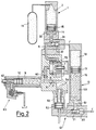
- the injection unit comprises a high-speed accumulator 1 consisting of a cylindrical chamber 14 in which a piston 15 slides.
- the upper part of the cylindrical chamber 14 is filled with nitrogen 2 under pressure from a cylinder 19, while the lower part is filled with fluid 30 which, pushed by the piston 15, through a connecting conduit 5, under the action of valve means constituted by a valve shell 31 and by a variable-action breech 32, causes the advancement of a piston 7 of an auxiliary cylinder/piston unit 6, 7 provided with a linear speed transducer 71.
- the cylindrical chamber 6 is filled in the front with fluid 40 which, pushed in a conduit 8 provided with a unidirectional valve 60 by the movement of the piston 7, causes the advancement of an injection piston 10 into a corresponding injection cylinder 9 provided with a rapid discharge valve 65 (of a type known in itself).
- a pressure multiplier 12 With the injection cylinder/piston unit 9, 10, provided with an injection stem 42, there is connected through a line 11, provided with a unidirectional valve 61, a pressure multiplier 12.
- the latter comprises an accumulator 13 consisting of a cylinder/piston 16, 17.
- the upper part of the cylindrical chamber 16 is filled with nitrogen under pressure 18 which causes the sliding action of the piston 17, while the lower part of the chamber 16 is filled with fluid 50 which, pushed by the piston 17, through the line 51 under the action of valve means constituted by a valve shell 20 and a variable-action breech 21, causes the advancement of a cylinder/piston pair 53, 52 which in turn with fluid 54 causes the sliding action of the injection piston 10 in the corresponding cylinder 9.
- the molten mass present in the injection cylinder 9 is compressed by the stem 42 in the proximity of the injection mouth (not shown).
- the larger diameter of the auxiliary cylinder 6 with respect to the injection cylinder 9 causes the speed of the auxiliary piston 7 during its stroke to be lower than that of the injection piston 10 and thus easily controllable.
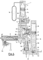
- the action of the pressure multiplier 12 then follows in a controlled manner. As illustrated in Fig. 3, in this stage the piston 17, pushed by the nitrogen under pressure 18 present in the upper part of the cylinder 16, starts its stroke and pushes the fluid 50 into the line 51 under the action of the valve means 20, 21 and, through the cylinder/piston pair 53, 52 and the corresponding control fluid 54, causing the sliding action with the multiplication of the pressure of the injection piston 10 in the corresponding cylinder 9.
- auxiliary piston 7 also operates in the ambit of the pressure multiplier 12.
- the piston 7 has a part with a smaller diameter which co-operates with the cylinder 6 supplied with fluid 30 from the accumulator 1 through a unidirectional valve 85 and communicating with the injection cylinder 9 through a valve 87 with a floating breech 88 and a part with a larger diameter which co-operates with a cylinder 86 supplied with fluid 50 from the accumulator 13 through the valve 20 with controlled breech 21 and communicating with the injection cylinder 9 through the unidirectional valve 61.
- Fig.s 5 - 8 also show two unidirectional valves 91 and 92 destined to the supply of fluid under pressure for recharging the accumulators 1 and 13 and a valve 93 with a floating breech 94 for discharging the fluid sent back by the injection piston 10 during the stages when it returns to the at rest position.
- the movement of opening of the breech 32 causes the supply of fluid 30 through the unidirectional valve 85 into the cylinder 6, where the piston 7 is thus caused to move forward so that, in turn, through the unidirectional valve 61, it causes the advancement of the injection piston 10 inside the injection cylinder 9 (with the valve 65 open) for the stage of injection of the metal into the casting cavity (Fig. 6).
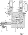
- the breech 21 is caused to open, allowing the transfer of high-pressure fluid from the accumulator 13 to the auxiliary cylinder 86, where the above fluid causes the auxiliary piston 7 to move backward and, due to the difference in area, the consequent creation of a multiplied pressure in the cylinder 6, which opens the valve 87 and goes to supply the injection piston 10 (Fig. 7). This creates the pressure multiplier effect on the molten metal pushed by the piston stem 42.
- valves 31, 32 and 21, 10 close again and thanks to the valve 65 the injection piston 10 is caused to return, thus discharging fluid through the valve 93 (Fig. 8).
Landscapes
- Engineering & Computer Science (AREA)
- Mechanical Engineering (AREA)
- Injection Moulding Of Plastics Or The Like (AREA)
- Moulds For Moulding Plastics Or The Like (AREA)
- Molds, Cores, And Manufacturing Methods Thereof (AREA)
- Fluid-Pressure Circuits (AREA)
Applications Claiming Priority (3)
| Application Number | Priority Date | Filing Date | Title |
|---|---|---|---|
| IT02039490A IT1248476B (it) | 1990-05-22 | 1990-05-22 | Gruppo di iniezione per macchina idraulica per pressofusione, munito di dispositivo per l`eliminazione di picchi di pressione all`iniezione |
| IT2039490 | 1990-05-22 | ||
| PCT/EP1991/000913 WO1991017850A1 (en) | 1990-05-22 | 1991-05-15 | Injection unit for a hydraulic die-casting machine, provided with a device for the elimination of pressure peaks at injection |
Publications (2)
| Publication Number | Publication Date |
|---|---|
| EP0530244A1 EP0530244A1 (en) | 1993-03-10 |
| EP0530244B1 true EP0530244B1 (en) | 1996-01-10 |
Family
ID=11166319
Family Applications (1)
| Application Number | Title | Priority Date | Filing Date |
|---|---|---|---|
| EP91909466A Expired - Lifetime EP0530244B1 (en) | 1990-05-22 | 1991-05-15 | Injection unit for a hydraulic die-casting machine, provided with a device for the elimination of pressure peaks at injection |
Country Status (7)
| Country | Link |
|---|---|
| EP (1) | EP0530244B1 (OSRAM) |
| CN (1) | CN1056643A (OSRAM) |
| AT (1) | ATE132781T1 (OSRAM) |
| DE (1) | DE69116361T2 (OSRAM) |
| ES (1) | ES2080948T3 (OSRAM) |
| IT (1) | IT1248476B (OSRAM) |
| WO (1) | WO1991017850A1 (OSRAM) |
Families Citing this family (4)
| Publication number | Priority date | Publication date | Assignee | Title |
|---|---|---|---|---|
| CN101774005B (zh) * | 2009-01-12 | 2012-05-30 | 深圳领威科技有限公司 | 一种油电混合的冷室压铸机压射系统 |
| CN101774004B (zh) * | 2009-01-12 | 2012-05-23 | 深圳领威科技有限公司 | 一种油电混合的热室压铸机压射系统 |
| CN101530902B (zh) * | 2009-04-16 | 2010-12-08 | 宁海县德科模塑有限公司 | 锌合金压铸模具的稳压装置 |
| CN102451899A (zh) * | 2010-10-25 | 2012-05-16 | 上海一达机械有限公司 | 压铸机液压系统的泵站油泵驱动装置 |
Family Cites Families (3)
| Publication number | Priority date | Publication date | Assignee | Title |
|---|---|---|---|---|
| DE2021539B2 (de) * | 1970-05-02 | 1971-04-22 | Wotan Werke Gmbh | Druckgiessmaschine mit multiplikator |
| DE3014868A1 (de) * | 1979-06-18 | 1981-01-22 | Buehler Ag Geb | Druckgiessmaschine |
| DE3123498C1 (de) * | 1981-06-13 | 1983-02-03 | Maschinenfabrik Müller-Weingarten AG, 7987 Weingarten | Vorrichtung zum beschleunigten Aufbau und zur Regulierung des Nachdruckes an Druckgiessmaschinen |
-
1990
- 1990-05-22 IT IT02039490A patent/IT1248476B/it active IP Right Grant
-
1991
- 1991-05-15 ES ES91909466T patent/ES2080948T3/es not_active Expired - Lifetime
- 1991-05-15 EP EP91909466A patent/EP0530244B1/en not_active Expired - Lifetime
- 1991-05-15 AT AT91909466T patent/ATE132781T1/de active
- 1991-05-15 WO PCT/EP1991/000913 patent/WO1991017850A1/en not_active Ceased
- 1991-05-15 DE DE69116361T patent/DE69116361T2/de not_active Expired - Fee Related
- 1991-05-22 CN CN91103431.5A patent/CN1056643A/zh active Pending
Non-Patent Citations (1)
| Title |
|---|
| BURGESS HILL pages 558 - 561; PF HARRISON: 'Die Casing: The Wotan Multiject injection system ' see column 2, line 27 - column 5, line 7 * |
Also Published As
| Publication number | Publication date |
|---|---|
| WO1991017850A1 (en) | 1991-11-28 |
| CN1056643A (zh) | 1991-12-04 |
| ES2080948T3 (es) | 1996-02-16 |
| IT1248476B (it) | 1995-01-19 |
| ATE132781T1 (de) | 1996-01-15 |
| IT9020394A0 (OSRAM) | 1990-05-22 |
| DE69116361D1 (de) | 1996-02-22 |
| EP0530244A1 (en) | 1993-03-10 |
| DE69116361T2 (de) | 1996-05-30 |
| IT9020394A1 (it) | 1991-11-22 |
Similar Documents
| Publication | Publication Date | Title |
|---|---|---|
| US4208879A (en) | Injection molding machines | |
| CA1109732A (en) | Free piston engine pump with energy rate smoothing | |
| US4022269A (en) | Die cast machines | |
| US4981426A (en) | Clamping mechanism in an injection molding machine | |
| US3891126A (en) | Injection cylinders of die cast machines | |
| JPS6033995B2 (ja) | 内燃機関用の燃料噴射ノズル | |
| EP0530244B1 (en) | Injection unit for a hydraulic die-casting machine, provided with a device for the elimination of pressure peaks at injection | |
| US4152921A (en) | Method and apparatus for the shock pressure shaping | |
| EP0422041A1 (en) | Hydraulic pressing apparatus. | |
| JP3662001B2 (ja) | ダイカストマシンの射出方法 | |
| US4150603A (en) | Fluid operable hammer | |
| US2299686A (en) | Hydraulic press | |
| US7210514B2 (en) | Die casting machine | |
| US4142397A (en) | Counterblowing machine hammer | |
| EP3554745B1 (en) | Injection assembly for pressure die casting systems | |
| US3327474A (en) | Hydraulic driving device for tools or the like, particularly for the movable mold parts of plastic die casting machines | |
| US4227442A (en) | Cylinder control device of hydraulic cylinder apparatus | |
| GB1254324A (en) | Improvements in or relating to pressure casting machines | |
| JP7392523B2 (ja) | ダイカスト成形方法および制御装置 | |
| US5875857A (en) | Accumulator charging system | |
| US4424674A (en) | Die casting machine | |
| JPH0337933Y2 (OSRAM) | ||
| US2862266A (en) | Pressure diecasting machine | |
| CA1121231A (en) | Fluid operable hammer or impactor | |
| SU822963A2 (ru) | Устройство дл подачи смазки вРАбОчую зОНу |
Legal Events
| Date | Code | Title | Description |
|---|---|---|---|
| PUAI | Public reference made under article 153(3) epc to a published international application that has entered the european phase |
Free format text: ORIGINAL CODE: 0009012 |
|
| AK | Designated contracting states |
Kind code of ref document: A1 Designated state(s): AT BE CH DE DK ES FR GB GR IT LI LU NL SE |
|
| 18D | Application deemed to be withdrawn |
Effective date: 19931201 |
|
| 17P | Request for examination filed |
Effective date: 19920220 |
|
| D18D | Application deemed to be withdrawn (deleted) | ||
| 17Q | First examination report despatched |
Effective date: 19950620 |
|
| GRAA | (expected) grant |
Free format text: ORIGINAL CODE: 0009210 |
|
| AK | Designated contracting states |
Kind code of ref document: B1 Designated state(s): AT BE CH DE DK ES FR GB GR IT LI LU NL SE |
|
| PG25 | Lapsed in a contracting state [announced via postgrant information from national office to epo] |
Ref country code: NL Free format text: LAPSE BECAUSE OF FAILURE TO SUBMIT A TRANSLATION OF THE DESCRIPTION OR TO PAY THE FEE WITHIN THE PRESCRIBED TIME-LIMIT Effective date: 19960110 Ref country code: GR Free format text: LAPSE BECAUSE OF FAILURE TO SUBMIT A TRANSLATION OF THE DESCRIPTION OR TO PAY THE FEE WITHIN THE PRESCRIBED TIME-LIMIT Effective date: 19960110 Ref country code: DK Effective date: 19960110 Ref country code: BE Effective date: 19960110 Ref country code: AT Effective date: 19960110 |
|
| REF | Corresponds to: |
Ref document number: 132781 Country of ref document: AT Date of ref document: 19960115 Kind code of ref document: T |
|
| ITF | It: translation for a ep patent filed | ||
| ET | Fr: translation filed | ||
| REG | Reference to a national code |
Ref country code: ES Ref legal event code: FG2A Ref document number: 2080948 Country of ref document: ES Kind code of ref document: T3 |
|
| REF | Corresponds to: |
Ref document number: 69116361 Country of ref document: DE Date of ref document: 19960222 |
|
| REG | Reference to a national code |
Ref country code: CH Ref legal event code: NV Representative=s name: PATENTANWAELTE GEORG ROEMPLER UND ALDO ROEMPLER |
|
| PG25 | Lapsed in a contracting state [announced via postgrant information from national office to epo] |
Ref country code: SE Effective date: 19960410 |
|
| PG25 | Lapsed in a contracting state [announced via postgrant information from national office to epo] |
Ref country code: GB Effective date: 19960515 |
|
| PGFP | Annual fee paid to national office [announced via postgrant information from national office to epo] |
Ref country code: FR Payment date: 19960515 Year of fee payment: 6 |
|
| PG25 | Lapsed in a contracting state [announced via postgrant information from national office to epo] |
Ref country code: LU Free format text: LAPSE BECAUSE OF NON-PAYMENT OF DUE FEES Effective date: 19960531 Ref country code: LI Effective date: 19960531 Ref country code: CH Effective date: 19960531 |
|
| PGFP | Annual fee paid to national office [announced via postgrant information from national office to epo] |
Ref country code: ES Payment date: 19960531 Year of fee payment: 6 |
|
| NLV1 | Nl: lapsed or annulled due to failure to fulfill the requirements of art. 29p and 29m of the patents act | ||
| PLBE | No opposition filed within time limit |
Free format text: ORIGINAL CODE: 0009261 |
|
| STAA | Information on the status of an ep patent application or granted ep patent |
Free format text: STATUS: NO OPPOSITION FILED WITHIN TIME LIMIT |
|
| 26N | No opposition filed | ||
| GBPC | Gb: european patent ceased through non-payment of renewal fee |
Effective date: 19960515 |
|
| REG | Reference to a national code |
Ref country code: CH Ref legal event code: PL |
|
| PG25 | Lapsed in a contracting state [announced via postgrant information from national office to epo] |
Ref country code: ES Free format text: LAPSE BECAUSE OF NON-PAYMENT OF DUE FEES Effective date: 19970516 |
|
| PG25 | Lapsed in a contracting state [announced via postgrant information from national office to epo] |
Ref country code: FR Free format text: LAPSE BECAUSE OF NON-PAYMENT OF DUE FEES Effective date: 19980130 |
|
| REG | Reference to a national code |
Ref country code: FR Ref legal event code: ST |
|
| PGFP | Annual fee paid to national office [announced via postgrant information from national office to epo] |
Ref country code: DE Payment date: 19990528 Year of fee payment: 9 |
|
| REG | Reference to a national code |
Ref country code: ES Ref legal event code: FD2A Effective date: 19990503 |
|
| PG25 | Lapsed in a contracting state [announced via postgrant information from national office to epo] |
Ref country code: DE Free format text: LAPSE BECAUSE OF NON-PAYMENT OF DUE FEES Effective date: 20010301 |
|
| PG25 | Lapsed in a contracting state [announced via postgrant information from national office to epo] |
Ref country code: IT Free format text: LAPSE BECAUSE OF NON-PAYMENT OF DUE FEES;WARNING: LAPSES OF ITALIAN PATENTS WITH EFFECTIVE DATE BEFORE 2007 MAY HAVE OCCURRED AT ANY TIME BEFORE 2007. THE CORRECT EFFECTIVE DATE MAY BE DIFFERENT FROM THE ONE RECORDED. Effective date: 20050515 |