EP0530153A2 - Zwischentrennvorrichtung für Fernsprechleitung - Google Patents
Zwischentrennvorrichtung für Fernsprechleitung Download PDFInfo
- Publication number
- EP0530153A2 EP0530153A2 EP92830280A EP92830280A EP0530153A2 EP 0530153 A2 EP0530153 A2 EP 0530153A2 EP 92830280 A EP92830280 A EP 92830280A EP 92830280 A EP92830280 A EP 92830280A EP 0530153 A2 EP0530153 A2 EP 0530153A2
- Authority
- EP
- European Patent Office
- Prior art keywords
- module
- telephone line
- voltage
- sectioning
- line
- Prior art date
- Legal status (The legal status is an assumption and is not a legal conclusion. Google has not performed a legal analysis and makes no representation as to the accuracy of the status listed.)
- Granted
Links
Images

Classifications
-
- H—ELECTRICITY
- H04—ELECTRIC COMMUNICATION TECHNIQUE
- H04M—TELEPHONIC COMMUNICATION
- H04M3/00—Automatic or semi-automatic exchanges
- H04M3/22—Arrangements for supervision, monitoring or testing
- H04M3/26—Arrangements for supervision, monitoring or testing with means for applying test signals or for measuring
- H04M3/28—Automatic routine testing ; Fault testing; Installation testing; Test methods, test equipment or test arrangements therefor
- H04M3/30—Automatic routine testing ; Fault testing; Installation testing; Test methods, test equipment or test arrangements therefor for subscriber's lines, for the local loop
- H04M3/301—Circuit arrangements at the subscriber's side of the line
Definitions
- the present invention relates to an intermediate telephone line sectioning device for trouble shooting in the telephone line sections.
- the diagnosis of the telephone line conditions is carried out by equipment located in the work center of the telephone exchange socalled A.C.L. by SIP, the Italian Telephone Company.
- A.C.L. by SIP, the Italian Telephone Company.
- the electrical parameters of the telephone line from the exchange to the user's telephone set through the telephone network can be monitored.
- such parameters are: low insulation between line wires and to the ground (zero potential), short circuits, breaks and foreign voltages on the line.
- Such parameters reflect the internal and external conditions (i.e. relative to the user's line) of the low frequency telephone system.
- Such method of the previous state of art requires, however, the intervention of a technician by the user so as to personally establish whether the trouble is to be ascribed to the user's line; the sectioning of the line is manually carried out by the technician himself so as to detect to what section of the telephone line the trouble is to be ascribed, i.e. either the user's line or the tie line.
- the main problem of such method is the labor and traveling cost.
- Another problem is the time of diagnosis which should be abbreviated.
- the present invention is aiming at avoiding the above mentioned problems.
- Another purpose of the present invention is of providing a device which is adapted to detect the sectioning and the re-make of the line by a signal fed to the telephone exchange.
- the invention such as claimed and illustrated in detail by a particular embodiment solves the problem of providing an almost immediate diagnosis of the line conditions and of establishing on the base of such a diagnosis whether the trouble is to be ascribed to the user's line or not.
- Such object is achieved by providing the intermediate line disconnecting switch between the user's line and the distribution telephone cable so as to effectively separate the two systems: internal (user) line and external line.
- the advantages of the invention consist in that the line diagnosis and trouble shooting time are reduced to the minimum due to the fact that the disconnecting switch of the invention is transparent to the measurement carried out by the control center.
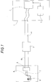
- telephone exchange 1 includes a module 3 generating an alternate voltage of 70 volts rms at a frequency of 50 Hz and a measuring instrument 2 for the line parameters which in the Italian Telephon Company SIP is called A.C.L.
- the main telephone line 4a connects telephone exchange 1 to distribution cabinet 5, and the telephone distribution line 4b connects the latter to the external user's line 7 ending in the jack 8 of telephone set 9.
- the intermediate line disconnecting switch 6 is placed between telephone distribution line 4b and external user's line 7.
- module 3 When module 3 generates a voltage of 70 volts rms at 50 Hz with a current limited to 80 mA during 2.5 seconds, the intermediate line disconnecting switch 6 opens the contacts sectioning the telephone line of the user's system.
- the intermediate line disconnecting switch 6 generates a signal at 90 Hz on the telephone lines 4a, 4b. Such signal is detected and coded by module 3. By generating during 4 seconds the same alternate voltage through module 3, the intermediate line disconnecting switch 6 closes the contacts sectioning the telephone line after the test of the same, as described thereafter.
- the signal at 90 Hz fed to the telephone line 4a, 4b is detected by a receiver included in the measuring device 2 and fed through an electronic interface system to the monitors of the operators in the measurement control center, thus signalling that the telephone line is sectioned.
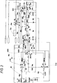
- Fig. 2 there are shown fourteen modules (or components) of the intermediate line disconnecting switch of the present invention, the circuit diagram of which is shown in detail in Fig. 3. The d.c.
- Module MD2 which is formed of a resistance R11 of 4700 ohms, an electrolytic capacitor C4 of 100 microfarads, and a Zener diode D5 of 12 volts levels through capacitor C11 and stabilizes to 12 volts through Zener diode D5 the pulsating voltage from module MD1.
- the charging voltage of capacitor C3 is applied to pin 5 of the integrated circuit U2B of the type LM 2904 (forming a half section of the integrated circuit U2 of the type LM 2904).
- the charging voltage of capacitor C3 is applied to pin 3 of integrated circuit U2A of the type LM 2904 included in module MD7, said integrated circuit comparing such voltage with a reference voltage V1 which is generated by module MD5 formed of the resistance R2 of 22 kohms and diodes D1, D2, D3 and is applied to pin 2 of the same integrated circuit.
- Diodes D1, D2, D3 are of the type 1N 4148.
- integrated circuit U2A When the voltage at pin 3 overcomes the reference voltage V1, integrated circuit U2A switches its output at pin 1 from “0" to “1” and together with resistances R3 of 1 kohm, R4 of 10 kohms and a tantalium capacitor C1 of 0.47 microfarad, which components are included in module MD7, supplies the base of a transistor Q1 of the type 2N 2222 included in module MD10 with a positive pulse of short duration, thus causing one of the two coils of a 3 V relay K1 (included in module MD12) to be shortly energized and then the opening of the two contacts of the relay so as to cause the telephone line to be sectioned.
- an operational amplifier U2B of the type LM 2904 included in module MD11 supplies the Hartley oscillator formed of components R9 of 47 ohm, R10 of 39 kohm, C7 of 1 microfarad, C8 of 4700 pF, coil L1, and transistor Q4 of the type 2N 2222, where Rx indicate resistances and Cx capacitors. All of such components are included in module MD11.
- the characteristics of coil L1 are shown in Table 1.
- Hartley oscillator generates a sinusoidal wave having a frequency of 90 kHz ⁇ 5 kHz and peak to peak voltage of 5 volts which is fed together with the sectioning voltage of the intermediate disconnecting switch from the control device of the latter mentioned above with reference to Fig.
- Module MD8 is formed of half a section of integrated circuit U1A, i.e. the operational amplifier U1A of the type LM 2904 having components R5, C2, D6 associated thereto and operating so as to set to zero the voltage at the ends of capacitor C3 during the pause between telephone calls.
- Module MD13 is formed of the discharger TRISIL of the type TPA 130A used to protect the intermediate line disconnecting switch from electrical pulse discharges. In particular it is provided for protecting the intermediate line disconnecting switch from atmospheric discharges which could occur on the telephone lines. It is placed in parallel with the contacts of relay K1. The latter, which is included in module MD12, has the function of sectioning and closing again the telephone line according to control signals from modules MD9 and MD10, as described above. Finally module MD14 is formed of resistance R8 of 68 kohm and 1 ⁇ 2 watt and capacitor C6 of 1 microfarad of the polyester type. The function thereof is of providing a voltage drop of about 6 volts a.c.
- the intermediate line disconnecting switch allows for a back-control of the line break at the user side as thoroughly described with reference to Figs. 1, 2 and 3.
- High frequency apparatus of the analogue and digital type (Mx, RSS, WCR, negative impedance amplifier of the "ZN" type) should not operate together.
- An alternate voltage of 70 volts rms and a short circuit current of 80 mA are needed.
- the control voltage of 70 volts rms has a frequency of 50 Hz. Therefore the whole assembly has a high signal to noise ratio.
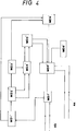
- Fig. 4 there is shown a block diagram of an alternate embodiment of the invention similar to the preceding embodiment except for the particular configuration of the intermediate sectioning block using different operating parameters.
- the operating frequencies are reduced to the typical values of the phonic band.
- it makes use of a lower operating voltage for the sectioning and the re-making of the line which is kept substatially constant between 18 and 20 Volt rms.
- Such intermediate line sectioning device is connected between the telephone line and the user's line as the preceding one. The detection is carried out by supplying the voltage of 18-20 Volt rms at 50-55 Hz from the exchange during a varying time of about 2.5 seconds.
- the intermediate line sectioning device opens the contacts for sectioning the telephone line of the user's installation.
- the sectioning device is resposive to such sectioning operation and generates a signal of varying frequency of 3000 ⁇ 500 Hz which is added to said sectioning voltage of 18-20 Volt at 50-55 Hz.
- Such signal is detected and coded in the control centre of the telephone exchange.
- the re-making of the sectioning contacts is due to an alternate voltage fed from the exchange to the sectioning device during a varying time of about 4 ⁇ 0.5 seconds.
- the frequency response of 3000 Hz fed from the sectioning device to the telephone line is detected by a receiver of the measuring equipment and transferred through an electronic interface to the monitors of the operators in the control and measurement centre.
- module MD1′ has the function of transforming the alternate voltage of the telephone line to a d.c. voltage and to block the d.c. component of the telephone line.
- Module MD2′ generates a main reference voltage of 2.5 volts and two very stable secondary voltages of 1.37 and 1.98 volts.
- Module MD3′ generates the time constant necessary for sectioning and re-making the line.
- Module MD4′ compares the voltage at its input with two reference voltages causing after such comparison the two outputs to be switched from logic 0 to 1 (0-1).
- Module MD5′ has the function of transforming the voltages at its two inputs to one pulse having the length of some milliseconds.
- Module MD6′ has the function of sectioning and re-making the telephone line as a result of two pulses applied at its inputs.
- Module MD7′ has the function of blocking the sectioning voltage preventing it from being fed to the user and of protecting the whole apparatus.
- Module MD8′ includes a buffer oscillator provided with current amplifier capable to generate a sinusoidal signal.
- Module MD9′ has the function of resetting the sectioning device and to re-make the telephone line when the user receives a phone call.
- module MD7′ which prevents such voltage from reaching the user
- module MD1′ which rectifies it to a d.c. voltage which is applied to module MD2′ thereby generating three reference voltages, two of which are applied to module MD4′ and the third to module MD3′.
- Module MD4′ compares in turn the voltage from module MD3′ with the previously described reference voltages. As a result of such comparison the two outputs of module MD4′ are switched from logic level 0 to 1, the first output after 2.5 seconds, and the second outputs after 3 seconds.
- Such outputs reach module MD5′ which convertes them into two pulses (one for each output) having the length of some milliseconds, which are applied to module MD6′ which in turn operates the sectioning of the telephone line by the first pulse and re-makes it by the second pulse.
- module MD6′ transfers the alternate control voltage to module MD8 so that such voltage is supplied to a sinusoidal buffer oscillator having a frequency of 3000 Hz ⁇ 500 Hz and a peak-to-peak amplitude of 3 volts which generates a signal fed through modules MD6′ and MD7′ to telephone line 4b.
- the control voltage is taken from module MD1′ and applied to module MD9′ which compares it with a reference voltage.
- this embodiment of the intermediate telephone line sectioning device of the present invention has all of advantages of the preceding embodiment such as the high sensitivity, the high signal-to-noise ratio, the independence of the inner electric parameters of the user's line, a. s. o.
- the device according to the invention operates independently of the electrical parameters of the internal user's line, i.e. short circuit between wires a-b, low insulation between the latter, foreign voltages on the telephone pair, psophometric noise and pulse noise.
Landscapes
- Engineering & Computer Science (AREA)
- Signal Processing (AREA)
- Sub-Exchange Stations And Push- Button Telephones (AREA)
- Solid-Sorbent Or Filter-Aiding Compositions (AREA)
- Electric Cable Installation (AREA)
- Telephone Function (AREA)
- Telephonic Communication Services (AREA)
- Monitoring And Testing Of Exchanges (AREA)
Applications Claiming Priority (4)
| Application Number | Priority Date | Filing Date | Title |
|---|---|---|---|
| ITRM910642 | 1991-08-29 | ||
| ITRM910642A IT1250085B (it) | 1991-08-29 | 1991-08-29 | Dispositivo di sezionamento intermedio di linea telefonica. |
| ITRM920230 | 1992-04-01 | ||
| ITRM920230A IT1253971B (it) | 1992-04-01 | 1992-04-01 | Dispositivo di sezionamento intermedio di linea telefonica e metodo dirilevamento del sezionamento. |
Publications (3)
| Publication Number | Publication Date |
|---|---|
| EP0530153A2 true EP0530153A2 (de) | 1993-03-03 |
| EP0530153A3 EP0530153A3 (de) | 1994-01-05 |
| EP0530153B1 EP0530153B1 (de) | 1998-08-05 |
Family
ID=26332002
Family Applications (1)
| Application Number | Title | Priority Date | Filing Date |
|---|---|---|---|
| EP92830280A Expired - Lifetime EP0530153B1 (de) | 1991-08-29 | 1992-05-29 | Zwischentrennvorrichtung für Fernsprechleitung |
Country Status (3)
| Country | Link |
|---|---|
| EP (1) | EP0530153B1 (de) |
| AT (1) | ATE169438T1 (de) |
| DE (1) | DE69226483T2 (de) |
Cited By (1)
| Publication number | Priority date | Publication date | Assignee | Title |
|---|---|---|---|---|
| FR2835382A1 (fr) * | 2002-01-31 | 2003-08-01 | Electricite De France | Dispositif de controle a distance d'une ligne filaire de telecommunication |
Citations (5)
| Publication number | Priority date | Publication date | Assignee | Title |
|---|---|---|---|---|
| US3843848A (en) * | 1973-01-12 | 1974-10-22 | Magnetic Controls Co | Telephone looptest system |
| EP0072721A1 (de) * | 1981-08-14 | 1983-02-23 | Michel Gadonna | System zur Lokalisierung von Kreisen und Unterbrechungen in einer Zweidrahtleitung |
| EP0144072A2 (de) * | 1983-11-29 | 1985-06-12 | Fujitsu Limited | Funkteilnehmerkonzentrationssystem |
| US4550225A (en) * | 1983-10-31 | 1985-10-29 | Keptel, Inc. | AC Signal-activated switching apparatus |
| DE3444872A1 (de) * | 1984-12-08 | 1986-06-12 | Vierling, Oskar, Prof. Dr.Phil.Habil., 8553 Ebermannstadt | Anordnung zum pruefen von teilnehmer-anschlussleitungen |
-
1992
- 1992-05-29 EP EP92830280A patent/EP0530153B1/de not_active Expired - Lifetime
- 1992-05-29 DE DE69226483T patent/DE69226483T2/de not_active Expired - Fee Related
- 1992-05-29 AT AT92830280T patent/ATE169438T1/de not_active IP Right Cessation
Patent Citations (5)
| Publication number | Priority date | Publication date | Assignee | Title |
|---|---|---|---|---|
| US3843848A (en) * | 1973-01-12 | 1974-10-22 | Magnetic Controls Co | Telephone looptest system |
| EP0072721A1 (de) * | 1981-08-14 | 1983-02-23 | Michel Gadonna | System zur Lokalisierung von Kreisen und Unterbrechungen in einer Zweidrahtleitung |
| US4550225A (en) * | 1983-10-31 | 1985-10-29 | Keptel, Inc. | AC Signal-activated switching apparatus |
| EP0144072A2 (de) * | 1983-11-29 | 1985-06-12 | Fujitsu Limited | Funkteilnehmerkonzentrationssystem |
| DE3444872A1 (de) * | 1984-12-08 | 1986-06-12 | Vierling, Oskar, Prof. Dr.Phil.Habil., 8553 Ebermannstadt | Anordnung zum pruefen von teilnehmer-anschlussleitungen |
Cited By (1)
| Publication number | Priority date | Publication date | Assignee | Title |
|---|---|---|---|---|
| FR2835382A1 (fr) * | 2002-01-31 | 2003-08-01 | Electricite De France | Dispositif de controle a distance d'une ligne filaire de telecommunication |
Also Published As
| Publication number | Publication date |
|---|---|
| EP0530153A3 (de) | 1994-01-05 |
| ATE169438T1 (de) | 1998-08-15 |
| EP0530153B1 (de) | 1998-08-05 |
| DE69226483T2 (de) | 1999-04-29 |
| DE69226483D1 (de) | 1998-09-10 |
Similar Documents
| Publication | Publication Date | Title |
|---|---|---|
| US5073919A (en) | Automatically testing telephone lines | |
| EP0454926B1 (de) | Endgerätleitungstest in Systemen mit Fasern bis zu dem Endgerät | |
| US6058161A (en) | System and method for programmable telephone subscriber line test | |
| US6026159A (en) | Integrated ringer for short telephone lines | |
| US4459437A (en) | Test system for locating breaks and short circuits in a two-lead line | |
| US3912882A (en) | Remote loop-back terminating unit for testing telephone | |
| EP1005209A2 (de) | Signalisierungsverfahren zum Aufrufen eines Testmoduses in einem Netzwerkschnittstellengerät | |
| US6144722A (en) | System and method for programmable telephone subscriber line test in ring mode | |
| US5956386A (en) | Telephone subscriber line diagnostics system and method | |
| US3843848A (en) | Telephone looptest system | |
| CA2101980C (en) | System and method for telephone network testing | |
| EP0287369A2 (de) | Fernunterbrechung und Kurzschlussgerät | |
| KR960011833B1 (ko) | 데이타 회선 단말 장치를 공중 전화 교환망과 로컬 전화기 세트에 접속하기 위한 커플링 장치 및 그를 포함하는 데이타 회선 단말 장치 | |
| US5115462A (en) | Remotely controlled apparatus for conditioning telephone line exclusive of metallic DC bypass pair | |
| EP0530153A2 (de) | Zwischentrennvorrichtung für Fernsprechleitung | |
| US4355209A (en) | Programmable line circuit | |
| US7020248B2 (en) | Apparatus and method for testing subscriber loop interface circuits | |
| US4336422A (en) | Toll restrictor | |
| US4847896A (en) | Monolithically integratable telephone circuit for supplying ringing signals to a subscriber's telephone line and for detecting an off the hook condition during ringing | |
| US4292480A (en) | Method and apparatus for locating telephones | |
| CA1069631A (en) | Method and apparatus for automatically identifying an individual calling party on a multiparty telephone line | |
| US4224476A (en) | Multiparty subscriber loop carrier systems | |
| US4106070A (en) | Hazardous voltage protector for telephone line | |
| US6912269B2 (en) | Test unit for use at a network interface device | |
| US5677941A (en) | Channel test unit |
Legal Events
| Date | Code | Title | Description |
|---|---|---|---|
| PUAI | Public reference made under article 153(3) epc to a published international application that has entered the european phase |
Free format text: ORIGINAL CODE: 0009012 |
|
| AK | Designated contracting states |
Kind code of ref document: A2 Designated state(s): AT BE CH DE DK ES FR GB GR IT LI LU MC NL PT SE |
|
| PUAL | Search report despatched |
Free format text: ORIGINAL CODE: 0009013 |
|
| AK | Designated contracting states |
Kind code of ref document: A3 Designated state(s): AT BE CH DE DK ES FR GB GR IT LI LU MC NL PT SE |
|
| 17P | Request for examination filed |
Effective date: 19940302 |
|
| 17Q | First examination report despatched |
Effective date: 19961122 |
|
| GRAG | Despatch of communication of intention to grant |
Free format text: ORIGINAL CODE: EPIDOS AGRA |
|
| GRAG | Despatch of communication of intention to grant |
Free format text: ORIGINAL CODE: EPIDOS AGRA |
|
| GRAH | Despatch of communication of intention to grant a patent |
Free format text: ORIGINAL CODE: EPIDOS IGRA |
|
| GRAH | Despatch of communication of intention to grant a patent |
Free format text: ORIGINAL CODE: EPIDOS IGRA |
|
| GRAA | (expected) grant |
Free format text: ORIGINAL CODE: 0009210 |
|
| AK | Designated contracting states |
Kind code of ref document: B1 Designated state(s): AT BE CH DE DK ES FR GB GR IT LI LU MC NL PT SE |
|
| PG25 | Lapsed in a contracting state [announced via postgrant information from national office to epo] |
Ref country code: NL Free format text: LAPSE BECAUSE OF FAILURE TO SUBMIT A TRANSLATION OF THE DESCRIPTION OR TO PAY THE FEE WITHIN THE PRESCRIBED TIME-LIMIT Effective date: 19980805 Ref country code: LI Free format text: LAPSE BECAUSE OF FAILURE TO SUBMIT A TRANSLATION OF THE DESCRIPTION OR TO PAY THE FEE WITHIN THE PRESCRIBED TIME-LIMIT Effective date: 19980805 Ref country code: GR Free format text: LAPSE BECAUSE OF NON-PAYMENT OF DUE FEES Effective date: 19980805 Ref country code: ES Free format text: THE PATENT HAS BEEN ANNULLED BY A DECISION OF A NATIONAL AUTHORITY Effective date: 19980805 Ref country code: CH Free format text: LAPSE BECAUSE OF FAILURE TO SUBMIT A TRANSLATION OF THE DESCRIPTION OR TO PAY THE FEE WITHIN THE PRESCRIBED TIME-LIMIT Effective date: 19980805 Ref country code: BE Free format text: LAPSE BECAUSE OF FAILURE TO SUBMIT A TRANSLATION OF THE DESCRIPTION OR TO PAY THE FEE WITHIN THE PRESCRIBED TIME-LIMIT Effective date: 19980805 Ref country code: AT Free format text: LAPSE BECAUSE OF FAILURE TO SUBMIT A TRANSLATION OF THE DESCRIPTION OR TO PAY THE FEE WITHIN THE PRESCRIBED TIME-LIMIT Effective date: 19980805 |
|
| REF | Corresponds to: |
Ref document number: 169438 Country of ref document: AT Date of ref document: 19980815 Kind code of ref document: T |
|
| REG | Reference to a national code |
Ref country code: CH Ref legal event code: EP |
|
| REF | Corresponds to: |
Ref document number: 69226483 Country of ref document: DE Date of ref document: 19980910 |
|
| PG25 | Lapsed in a contracting state [announced via postgrant information from national office to epo] |
Ref country code: SE Free format text: LAPSE BECAUSE OF FAILURE TO SUBMIT A TRANSLATION OF THE DESCRIPTION OR TO PAY THE FEE WITHIN THE PRESCRIBED TIME-LIMIT Effective date: 19981105 Ref country code: PT Free format text: LAPSE BECAUSE OF FAILURE TO SUBMIT A TRANSLATION OF THE DESCRIPTION OR TO PAY THE FEE WITHIN THE PRESCRIBED TIME-LIMIT Effective date: 19981105 Ref country code: DK Free format text: LAPSE BECAUSE OF FAILURE TO SUBMIT A TRANSLATION OF THE DESCRIPTION OR TO PAY THE FEE WITHIN THE PRESCRIBED TIME-LIMIT Effective date: 19981105 |
|
| ET | Fr: translation filed | ||
| NLV1 | Nl: lapsed or annulled due to failure to fulfill the requirements of art. 29p and 29m of the patents act | ||
| ET1 | Fr: translation filed ** revision of the translation of the patent or the claims | ||
| REG | Reference to a national code |
Ref country code: CH Ref legal event code: PL |
|
| K2C3 | Correction of patent specification (complete document) published |
Effective date: 19980805 |
|
| PG25 | Lapsed in a contracting state [announced via postgrant information from national office to epo] |
Ref country code: LU Free format text: LAPSE BECAUSE OF NON-PAYMENT OF DUE FEES Effective date: 19990529 |
|
| PLBE | No opposition filed within time limit |
Free format text: ORIGINAL CODE: 0009261 |
|
| STAA | Information on the status of an ep patent application or granted ep patent |
Free format text: STATUS: NO OPPOSITION FILED WITHIN TIME LIMIT |
|
| 26N | No opposition filed | ||
| PG25 | Lapsed in a contracting state [announced via postgrant information from national office to epo] |
Ref country code: MC Free format text: LAPSE BECAUSE OF NON-PAYMENT OF DUE FEES Effective date: 19991130 |
|
| REG | Reference to a national code |
Ref country code: GB Ref legal event code: IF02 |
|
| PGFP | Annual fee paid to national office [announced via postgrant information from national office to epo] |
Ref country code: GB Payment date: 20020529 Year of fee payment: 11 |
|
| PGFP | Annual fee paid to national office [announced via postgrant information from national office to epo] |
Ref country code: FR Payment date: 20020531 Year of fee payment: 11 |
|
| PGFP | Annual fee paid to national office [announced via postgrant information from national office to epo] |
Ref country code: DE Payment date: 20020712 Year of fee payment: 11 |
|
| PG25 | Lapsed in a contracting state [announced via postgrant information from national office to epo] |
Ref country code: GB Free format text: LAPSE BECAUSE OF NON-PAYMENT OF DUE FEES Effective date: 20030529 |
|
| PG25 | Lapsed in a contracting state [announced via postgrant information from national office to epo] |
Ref country code: DE Free format text: LAPSE BECAUSE OF NON-PAYMENT OF DUE FEES Effective date: 20031202 |
|
| GBPC | Gb: european patent ceased through non-payment of renewal fee |
Effective date: 20030529 |
|
| PG25 | Lapsed in a contracting state [announced via postgrant information from national office to epo] |
Ref country code: FR Free format text: LAPSE BECAUSE OF NON-PAYMENT OF DUE FEES Effective date: 20040130 |
|
| REG | Reference to a national code |
Ref country code: FR Ref legal event code: ST |
|
| PG25 | Lapsed in a contracting state [announced via postgrant information from national office to epo] |
Ref country code: IT Free format text: LAPSE BECAUSE OF NON-PAYMENT OF DUE FEES;WARNING: LAPSES OF ITALIAN PATENTS WITH EFFECTIVE DATE BEFORE 2007 MAY HAVE OCCURRED AT ANY TIME BEFORE 2007. THE CORRECT EFFECTIVE DATE MAY BE DIFFERENT FROM THE ONE RECORDED. Effective date: 20050529 |