EP0529185A1 - Vibratory conveyor - Google Patents
Vibratory conveyor Download PDFInfo
- Publication number
- EP0529185A1 EP0529185A1 EP92102906A EP92102906A EP0529185A1 EP 0529185 A1 EP0529185 A1 EP 0529185A1 EP 92102906 A EP92102906 A EP 92102906A EP 92102906 A EP92102906 A EP 92102906A EP 0529185 A1 EP0529185 A1 EP 0529185A1
- Authority
- EP
- European Patent Office
- Prior art keywords
- mass
- oscillating
- spring
- vibrating
- elements
- Prior art date
- Legal status (The legal status is an assumption and is not a legal conclusion. Google has not performed a legal analysis and makes no representation as to the accuracy of the status listed.)
- Granted
Links
Images


Classifications
-
- B—PERFORMING OPERATIONS; TRANSPORTING
- B65—CONVEYING; PACKING; STORING; HANDLING THIN OR FILAMENTARY MATERIAL
- B65G—TRANSPORT OR STORAGE DEVICES, e.g. CONVEYORS FOR LOADING OR TIPPING, SHOP CONVEYOR SYSTEMS OR PNEUMATIC TUBE CONVEYORS
- B65G27/00—Jigging conveyors
- B65G27/10—Applications of devices for generating or transmitting jigging movements
- B65G27/28—Applications of devices for generating or transmitting jigging movements with provision for dynamic balancing
- B65G27/30—Applications of devices for generating or transmitting jigging movements with provision for dynamic balancing by means of an oppositely-moving mass, e.g. a second conveyor
-
- B—PERFORMING OPERATIONS; TRANSPORTING
- B65—CONVEYING; PACKING; STORING; HANDLING THIN OR FILAMENTARY MATERIAL
- B65G—TRANSPORT OR STORAGE DEVICES, e.g. CONVEYORS FOR LOADING OR TIPPING, SHOP CONVEYOR SYSTEMS OR PNEUMATIC TUBE CONVEYORS
- B65G27/00—Jigging conveyors
- B65G27/08—Supports or mountings for load-carriers, e.g. framework, bases, spring arrangements
Definitions
- the invention relates to a vibration conveyor according to the preamble of claim 1 or 9.
- a conveyor of this type designed as a longitudinal vibratory conveyor is known in principle (DD-PS 257 737).
- Longitudinal vibration conveyors are used in particular in automatic manufacturing processes, i. H. used in manufacturing or assembly machines for the storage and transfer of workpieces or components, especially small components.
- the conveyor element in these longitudinal vibratory conveyors is in most cases a conveyor trough which is then attached to a first oscillating element of the oscillating system which is assigned to the useful mass.
- the longitudinal vibration conveyor of the type mentioned at the outset is also required for the usable mass, an oscillating element forming a counter mass is also provided swinging on a base element.
- the drive which is formed by a magnet coil with a magnetic core and an associated magnet armature that changes in amplitude through its current, causes the two oscillating elements or the useful mass and counterweight to oscillate or vibrate in opposite directions, namely the at least part of the useful mass forming conveyor trough in such a way that it carries out a reciprocating movement with a larger movement component extending in the longitudinal direction of the trough and with a smaller movement component running in the vertical direction.
- the components are moved by this vibration movement in the longitudinal direction of the conveyor trough, ie in the conveying direction will.
- the useful mass is largely formed by the mass of the conveying element, which is adapted to the respective application and the mass of which can therefore vary from application to application.
- the known longitudinal vibratory conveyor requires a corresponding processing of the conveying element, for which it is then necessary to remove the conveying element from the oscillating system, to process it and to mount it again on the oscillating system. Since the longitudinal vibration conveyor and in particular its conveying element cooperate with other elements of a system, it is also necessary to readjust it exactly with respect to the other elements of the system after each new installation of the conveying element. This workload is particularly great when the conveying element has to be dismantled several times, processed and then reassembled until the optimum mass balance has been achieved.
- a vibration conveyor in the form of a vibratory bowl conveyor (DE-OS 39 40 111).
- This known conveyor has the basic advantage that a largely vibration-free arrangement is possible due to the special design of the vibration system, ie vibrations are not transmitted to a machine frame or machine table when the vibration conveyor is switched on, which (vibrations) could disrupt other functional elements of a system, for example an assembly line .
- a disadvantage of this known conveyor is, among other things, that the first vibrating system in particular is an integral part of a pot, so the pot in question cannot be removed from the vibrating system and / or can be exchanged for another pot.
- a very special vibration system is provided for each pot size and shape.
- the object of the invention is to show a vibration conveyor which avoids the aforementioned disadvantages, enables mass balancing or balancing of the moment of inertia easily and without dismantling the conveyor or the conveying element, and more flexible usability.
- a vibration conveyor is designed according to the characterizing part of claim 1 or 9.
- the second vibrating element forms at least one partial area, which is provided perpendicular to the conveying direction to the side of the conveying element and / or from the first vibrating element and on which means for attaching a mass that enters the counter mass are formed.
- an auxiliary mass which can be changed in size is freely accessible in this partial region.
- This auxiliary mass can then be used for mass balancing or mass compensation when using conveyor elements with different masses.
- "Freely accessible" in the sense of the invention means that this auxiliary mass or other elements, which are designated as freely accessible, are provided in such a way that no dismantling of the conveying element or other functional elements for a change, for an adjustment or for a comparison of the vibrating system are necessary, except, of course, those elements that make up the auxiliary mass form. This makes it possible to carry out mass balancing in the case of functional vibratory conveyors, ie in particular when the conveying element is installed.
- the respective auxiliary mass is preferably formed from individual masses, which are either connected to the second oscillating element or removed from it in accordance with the required mass balance.
- the vibratory conveyor according to the invention preferably ensures that the useful mass has as few unnecessary mass elements as possible, and in particular that the first vibrating element has the smallest possible mass. This then results in a relatively small counter mass, so that a predetermined change in the auxiliary mass can bring about a relatively large change in the counter mass as a whole.
- the second oscillating element is designed such that it has at least one partial area on each side of the conveying element for receiving at least one freely accessible auxiliary mass.
- the two oscillating elements are arranged on both sides at a distance from one another from a vertical central plane including the conveying direction.
- the conveying element is fastened to the first vibrating element or to the top thereof, the top of the second vibrating element then forms a freely accessible area for fastening the auxiliary masses.
- mass balancing i.e. The compensation of the different masses of different conveying elements used with the vibration conveyor also takes place in that at least one spring element of the useful mass or an oscillating system including the useful mass can be changed or adjusted such that the resonance or natural frequency of the useful mass is equal to or approximately equal to the natural frequency the counter mass is. So there is a change in the spring constant of at least one spring element of the useful mass and no change in the counter mass or auxiliary mass.
- the counter mass is preferably selected such that it is equal to the useful mass if the one of the different conveying elements intended for use is the one with the greatest mass. This also means that when the conveyor element with the largest mass is used, the spring constants of the spring elements of the useful and counter mass are the same.
- the vibration conveyor is preferably operated so that the resonance or natural frequency of the vibration system, which is a function of the mass or counter-mass and the spring constants generated by the spring elements, is as equal as possible to the frequency of the drive, for example a magnet arrangement operated at mains frequency.
- the spring elements form fixed spring elements which hold the elements of the vibration system together, and additionally removable and / or interchangeable spring elements.
- the vibration conveyor is designed as a spiral conveyor or vibratory spiral conveyor.
- the element forming the conveyor path which is preferably a pot, is again provided on the first oscillating element in a removable or replaceable manner.
- the adjustment necessary to compensate for different sizes of pots etc. takes place by changing the dynamic moment of inertia of the counter-oscillating mass, namely by changing the mass (mass comparison) and / or by changing the distance of a mass element from the central axis of the Vibration system. Auxiliary masses are then again freely accessible for mass balancing.
- the usable mass has as few unnecessary mass elements as possible, in particular also the first oscillating element has the smallest possible mass or has the lowest possible moment of inertia. This then also results in a relatively small counter-vibration mass, so that a certain change in the auxiliary masses can bring about a relatively large change in the counter-vibration mass or the moment of inertia as a whole.
- the different sizes or masses of the pots used are not compensated by mass balancing, but at least in a predetermined range by changing or adjusting the spring characteristics or spring constants of the spring arrangements assigned to the useful mass, such that in each case used pot the natural frequency of the useful mass is equal to the natural frequency of the counter-oscillating mass.
- the dynamic moment of inertia of the counter-oscillating mass is selected in such a way that when using the largest pot provided, i.e. of the pot that brings the greatest dynamic moment of inertia for the useful mass, the dynamic moment of inertia of the useful mass is equal to or greater than the dynamic moment of inertia of the vibrating mass.
- the vibratory bowl feeder is preferably operated so that the resonance or natural frequency of the vibration system, which is a function of the dynamic moment of inertia under spring characteristic in the spring constant is, if possible, equal to the frequency of the drive, for example the mains frequency of a magnet arrangement operated at this frequency.
- An optimal way of working in this sense can be achieved in any case by adjusting or adjusting the spring constants.
- fixed spring elements which hold the elements of the vibration system together, and additionally removable and / or exchangeable spring elements are provided for adapting the spring characteristics or spring constants.
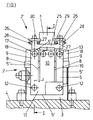
- 1 is a conveyor rail or conveyor trough which forms a straight, essentially horizontal conveyor section of the longitudinal vibration conveyor for small or Small components.
- This conveyor trough 1 is provided on a vibration drive or vibration system 2 of the longitudinal vibratory conveyor.
- the vibration system 2 is in turn attached to a machine frame or machine table 4 of a production machine by means of a base plate 3.
- a vibration movement is exerted on the conveyor trough 1 by the vibration system 2 in such a way that the components move in the direction of arrow A in the longitudinal direction of the conveyor trough.
- a leaf spring assembly formed by three leaf springs 5 arranged one above the other in the manner of lamellae is fastened as a spring element, using two fastening screws 6 and two clamping or holding plates 7, clamp the leaf springs 5 of each leaf spring assembly between them when the fastening screws 6 are tightened and engage in the thread of the base plate 3.
- each leaf spring 5 As shown in particular in FIG. 1, the leaf springs, each of the same shape and made from a suitable spring leaf, each have an essentially rectangular cut.
- the shorter sides of this blank are designated 5 'in FIG. 1 and the longer sides 5''.
- each leaf spring 5 is provided with two slots 8 which run parallel to the longer sides 5''and are each at the same distance from that in FIG. 1 lower, shorter side 5 'of the blank end at a distance which corresponds approximately to the width of the rectangular clamping plates 7.
- the leaf springs 5 are double slotted and form three tongues 9 and 10 separated by the slits 8, which are integrally connected to each other at the closed end of the slits 8 through the non-slotted area 11 of the leaf spring 5 concerned.
- the central tongue 10 has a width in the direction perpendicular to the slots 8, ie in an axial direction parallel to the shorter sides 5 ', which is twice as large as the corresponding width of an outer tongue 9, ie the sum of the widths of the two outer tongues 9 is equal to the width of the middle tongue 10.
- bores 12 for the fastening screws 6 are provided on an axis parallel to the shorter side 5 '.
- the middle tongue 10 has on its free, i.e. H. two bores 13 and the two outer tongues 9 each have a bore 13 at the end remote from section 11. These bores in turn lie on a common line parallel to the shorter sides 5 '.
- each leaf spring assembly is arranged in the same orientation and with respect to the slots 8 and bores 12 and 13 one above the other.
- the middle tongues 10 of the leaf springs 5 of the leaf spring assemblies are each fastened with the aid of fastening screws 14 penetrating through the bores 13 on the front-side, opposite the vertical beveled ends of an oscillating element 15 made of light metal.
- This oscillating element 15 is essentially an elongated cuboid body oriented with its axis in the conveying direction A, which has a rectangular cross section in a cross-sectional plane perpendicular to the conveying direction A (FIG. 4) and in the region of one end with a projection 16 projecting beyond the lower cross-sectional side is provided.
- the free ends of the tongues 9 are each fastened to a holding block 18 with the aid of fastening screws 17 penetrating through the bores 13 there, to be precise on a holding surface 18 which is inclined relative to the vertical surface.
- the holding blocks 18, of which a total of four are provided, are in turn attached to the top of a plate-shaped, that is, a vibrating element 19 designed as a rectangular plate, in such a way that each holding block 18 protrudes beyond the horizontal top of this plate-shaped vibrating element 19.
- the leaf springs 5 or the leaf spring assemblies formed by them By fastening the leaf spring assemblies formed by the leaf springs 5 to a surface inclined with respect to the vertical, both on the base plate 3 and on the oscillating element 15 and the holding blocks 18, the leaf springs 5 or the leaf spring assemblies formed by them have an inclination with respect to the vertical or with respect to a vertical plane running perpendicular to the conveying direction, ie, starting from the upper side 5 ', the leaf springs 5 close an angle of less than 90 ° with the axis of the conveying direction, which opens in the conveying direction, as is necessary for a vibration movement of the components in conveying direction A.
- the plate-shaped oscillating element 19 is arranged at a certain distance below the oscillating element 15 and has in the region of one end face of the oscillating system 2, i.e. H. in the illustration chosen for FIG. 2 in the region of the left end there, a recess 20 open towards this end, through which the projection 16 extends, in such a way that this projection also extends in the region of the recess 20 in the region of all its surfaces is spaced apart from the oscillating element 19 and the projection 16 projects with its free end relatively far beyond the underside of the oscillating element 19, which is essentially in the form of a rectangular plate.
- the projection 16 serving as a magnet armature block 21 made of ferromagnetic material, i. H. made of steel.
- the figures further show that the oscillating element 19 protrudes perpendicularly or transversely to the conveying direction A on both sides via the oscillating element 15 and the retaining blocks 18 are also attached to these protruding areas, in such a way that they are located on both sides of the oscillating element 15, however each at a predetermined distance from the vibrating element 15.
- the vibrating element 19 lies with its longer sides parallel to the conveying direction A and with its shorter sides perpendicular to this conveying direction.
- At the bottom of the vibrating element 19 are made of a ferromagnetic material, for. B. made of steel magnetic core 22 and a magnetic core 23 surrounding this core are provided.
- a U-shaped holding block 24 is attached to this oscillating element, which has a section 25 extending transversely to the conveying direction A, with the underside of the respective holding block 24 is attached to the top of the vibrating element 15.
- the cuboid section 25 is provided in one piece with a projection 26. The two projections 26 and the section 25 form the upwardly open U-shape of the respective bracket 24.
- each bracket 24 which have a distance on their mutually facing sides that is greater than the outer width of the conveyor trough 1, this conveyor trough is held and connected to the vibrating element 15.
- a grub or adjusting screw 27 with lock nut 28 is provided in a thread of each projection 26 such that this adjusting screw 27 with its axis parallel to the longitudinal extent of section 25, i. H. in the horizontal direction and perpendicular to the conveying direction A.
- the lock nut 28 is located on the outside of the respective projection 26 facing away from the guide trough 1. With an end projecting beyond the inside of the respective projection 26 facing the conveyor trough 1, each adjusting screw 27 forms an adjustable stop abutting against a longitudinal side of the conveyor trough 1.
- the position or orientation of the conveying trough 1 with respect to the oscillating element 15 and thus with respect to the oscillating system 2 as a whole can be adjusted.
- the setting once made is determined by tightening the lock nuts 28, so that even after a possible removal of the conveyor trough 1, z. B. for repair purposes or for post-processing, the conveyor trough 1 can be reattached in the correct orientation without the need for readjustment by inserting it into the holding blocks 24 on the oscillating system 2.
- Locking plates 29 provided with elongated holes are used for the final locking, one of which is provided on the upper side of this projection 26, i. H. is held by a fastening screw 30.
- the oscillating element 15 and the conveyor trough 1 and all parts connected to the oscillating element 15 and / or the conveyor trough 1 form the useful mass of the oscillating system 2 and the oscillating element 19 with all parts provided on these elements, in particular with the magnetic core 22 and the relatively heavy magnet coil 23 , but also with the holding blocks 18, the counterweight of the vibration system.
- the useful mass and the counter mass are arranged with their center of gravity on a line which lies essentially in a vertical plane extending in the conveying direction A.
- the two masses are further coordinated so that when the solenoid 23 is switched on, that is to say an alternating current is applied to the solenoid 23, both masses oscillate relative and in opposite directions to one another with elastic deformation of the leaf springs 5 or their tongues 9 and 10 without vibrating movements on the base plate 3 and thus be transferred to the machine table 4.
- This ideal state is achieved in the embodiment shown, in which the spring constant formed by the tongue 10 and two tongues 9 is in each case the same size, when the counter mass and the useful mass are the same size.
- an auxiliary mass 32 which can be changed in size is provided between two holding blocks 18.
- Each of the two auxiliary masses 32 each consists of one or more plate-like individual masses 33 made of metal or steel, which are connected to one another by means of screws 34 to form the auxiliary mass and are held on the oscillating element 19 of the counter mass. Since this vibrating element is on the outside, i. H. is accessible, the two auxiliary masses 32 can be adjusted by removing one or more auxiliary masses 33 or vice versa by adding one or more auxiliary masses 33 so that an optimal adaptation of the useful mass and the counter mass is achieved. In order to achieve an effective adjustment of the counter mass by changing the auxiliary mass, it is also essential in the embodiment shown that the useful mass is kept as small as possible, ie. H.
- the part of the oscillating system 2 which enters the useful mass does not have any unnecessary mass elements and the oscillating element 15 is also made of a material with a low specific weight or specific mass, so that the counter mass can accordingly be kept small.
- the oscillating element 15 is also made of a material with a low specific weight or specific mass, so that the counter mass can accordingly be kept small.
- elements with a high mass in particular the magnetic core 22 and the magnetic coil 23, are fastened to the oscillating element 19 which forms the countermass.
- the individual masses 33 are each of the same design in the illustrated embodiment. In principle, it is of course also possible to provide heavier and lighter individual masses 33 in order to enable the counter mass to be adapted very precisely in small increments to the useful mass which is also mainly determined by the conveyor trough 1 and the functional elements provided there.
- the vibrating element 15 assigned to the useful mass is on the inside and the vibrating element 19 assigned to the counterweight is on the outside, ie the vibrating element 19 assigned to the counterweight is transverse to the conveying direction A on both sides the vibrating element 15 protrudes and the auxiliary masses 32 are provided there, the above-described mass adjustment using the individual masses 33 is possible in particular even with the longitudinal vibratory conveyor mounted on the machine table 4, ie the longitudinal vibratory conveyor does not have to be removed from the machine table 4 for mass adaptation.
- the oscillating element 19 assigned to the counter mass is provided on the outside in the manner described above, it is also possible to use a holding block 35, which is provided on the underside of the oscillating element 19 and carries the magnetic core 22 with the magnetic coil 23, with fastening screws 36 on the oscillating element 19 to attach, each on the laterally projecting beyond the vibrating element 15 areas of the vibrating element 19, d. H. provided in the region of the long sides of this oscillating element and are thus freely accessible from above (after the auxiliary masses 32 have been removed).
- a total of two fastening screws 36 are provided, specifically one fastening screw in the region of each longitudinal side of the oscillating element 19.
- the fastening screws 36 engage through bores 37 of the oscillating element 19 in threaded bores of the holding block 35.
- the bores 37 have one in particular in the conveying direction A.
- Cross section which is larger than the outer diameter of the fastening screws 36, so that an adjustment of the holding block 35 with the magnetic core 22 and the magnetic coil 23 not only relative to the oscillating element 19, but also relative to the oscillating element 15 or to the magnetic armature 21 provided there and thus an adjustment of the magnet or air gap between the magnet armature 21 and the magnet core 22 is freely possible from the outside, again again without the need to dismantle the longitudinal vibration conveyor from the machine table 4.
- An optimal setting of the magnet or air gap between the magnet armature 1 and the magnet core 22 is essential in order on the one hand to have a relative movement between the magnet armature 21 and the magnet core 22 or the opposite movement Swinging movement between the useful mass and counter mass without allowing an impact between the magnet armature 21 and the magnet core 22, and on the other hand to keep the magnet or air gap as small as possible. Too large an air or magnetic gap would mean too little magnetic flux or too little electrical inductance for the magnetic coil 23 and thus too high a current which could possibly destroy the magnetic coil.
- two diaphragms or wall elements 38 are removably attached to the two longitudinal sides of the elongated base plate 3 running parallel to the conveying direction A by means of fastening screws 39.
- Each wall element 38 extends with its upper, substantially parallel to the conveying direction A horizontal side 38 'into the vicinity of the underside of the plate-shaped oscillating element 19, whereby of course a gap allowing the oscillating movement remains between this side 38' and the underside of the oscillating element 19.
- the oscillating element 19 projects slightly with its two longitudinal sides over the outer surface of the respective wall element 38.
- the two wall elements 38 continue to extend to the two end faces of the base plate 3, which support the leaf springs 5.
- the shorter sides 38 ′′ there which are provided at a distance from the respective leaf spring assembly, run obliquely to the vertical, i. H. parallel to the leaf springs of the adjacent leaf spring assembly.
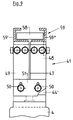
- This vibration conveyor consists of a base plate 40 fastened to the machine table 4 or to another support element or console, which is part of a vibration system 41.
- this vibration system has two vibration elements 41 and 42, which are made of a suitable metal with the lowest possible specific weight, for example of an aluminum alloy, and with regard to Their shape essentially consists of a yoke section 42 'or 43' which extends in the axis of the conveying direction A and which is located at a distance above the base plate 40, as well as a leg 42 '' or from this yoke section which extends vertically downwards .43 ''.
- the two swivel elements 42 and 43 are provided next to one another and at a distance from one another transversely to the conveying direction A, to be precise on both sides of a vertical central plane including the conveying direction A.
- the two oscillating elements 42 and 43 are connected to the base plate 40 via two leaf spring assemblies 45 and 46 each having a plurality of leaf springs 44.
- the horizontal width of the base plate 40 perpendicular to the conveying direction A is approximately equal to the corresponding width of the arrangement formed by the two oscillating elements 42 and 43.
- each leaf spring 44 is each designed in such a way that each leaf spring 44 forms two tongues 48 and 49 which are identical in terms of their shape through a central slot 47 and which are connected to one another in the lower region of the respective leaf spring 44 by a continuous section 44 '.
- the tongue 48 of each leaf spring 44 is attached to the left or right end of the yoke section 42 'in FIG. 5 by means of two fastening tabs 50 and the tongue 49 of each leaf spring 44 is attached to the left or right end in FIG. 5 by means of two screws 50 of the yoke section 43 'attached.
- the leaf springs 44 are fastened to the base plate 40 or to lugs 40' protruding there above by means of screws 50 and washers 51.
- the leaf spring arrangements or packages 45 and 46 each having two leaf springs 44 in the embodiment shown are inclined again with respect to the vertical.
- the leg 42 ′′ is offset in the conveying direction A with respect to the leg 43 ′′, ie the leg 42 ′′ is located at the left end in FIG. 5 and in relation to the conveying direction A Leg 43 ′′ at the right end in FIG. 5, with respect to the conveying direction A, of the end of the oscillating system 41.
- the magnet coil 52 is fastened to the leg 43 ′′ in such a way that this magnet coil is located within the between the two legs 42 ′. 'and 43''formed space is arranged below the yoke sections 42' and 43 '.
- a magnet armature 53 which interacts with the magnet coil 52, is fastened to the leg 42 ′′. Between the iron core of the magnet coil 52 and the magnet armature 53, the magnet gap is again formed with a predetermined width, specifically in a vertical plane running perpendicular to the conveying direction A.
- the vibrating element 42 forms part of the useful mass, i.e. on this vibrating element, the conveyor rail or conveyor trough 1 is fastened, with the aid of a mounting bracket 54, which is screwed with its one horizontal leg 54 'to the underside of the conveyor trough 1 and with its vertical other leg 54' 'into a lateral recess of the Yoke section 42 'engages and is fixed there by means of screws 55.
- the mounting bracket 54 or its leg 54 '' has slots 56 which are open towards the edge of the leg 54 '' which is remote from the leg 54 '.
- the vibrating element 43 forms part of the countermass, ie on the vibrating element 43 or on the top of the yoke section 43 ', the auxiliary mass 57, which in turn consists of several individual masses, is provided on the side of the conveyor groove 1 with the aid of a fastening angle 54.
- Fig. 9 shows, there is basically the possibility, with the promotion of certain, for. B. particularly wide components 58 to use both vibrating elements 42 and 43 for the movement of these components 58.
- a divided conveyor trough 59 is then used instead of the conveyor trough 1, which in the embodiment shown has a substantially C-shaped cross section which is open at the top and consists of the two elements 59 'and 59' '. Each of these elements is suitably attached to the top of a vibrating element 42 or 43.
- the two elements 59 'and 59' 'of the conveying trough or rail 59 then move in opposite directions, corresponding to the oscillating elements 42 and 43, so that overall a conveying effect on the components 58 in the direction of arrow A Fig. 5 is exercised, ie these components 58 move in the conveying direction.
- the mass of the elements 59 'and 59' 'and / or by an additional mass balance it is again ensured that the useful mass and the counter mass are the same or approximately the same, with the same spring constants of the tongues 48 and 49.
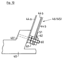
- a leaf spring 44a can be provided, which is in any case firmly connected to the base plate 40 and the oscillating elements 42 and 43, respectively.
- further removable or exchangeable leaf springs 44b are then provided.
- threaded bolts 60 are used, on which the fixed, i.e. non-replaceable leaf springs 44a are fixed with the help of lock nuts 61.
- the nuts 62 serve to fix the exchangeable leaf springs 44b.
- FIG. 11 shows a vibration conveyor in which the vibration system in conveyor troughs 1 with different masses is not compensated for by a corresponding change in the auxiliary mass 57, but by changing the spring constants of the leaf springs assigned to the oscillating element 42, specifically in the form that the natural frequency of the useful mass including the vibrating element 42, the conveyor trough 1, etc. is equal to the natural frequency of the counter mass including the vibrating element 43, the auxiliary mass 57, etc.
- the leaf springs 44 or 44a and 44b forming the tongues 48 and 49
- separate leaf springs are provided for the oscillating elements 42 and 43, i.e. the leaf springs 63 for the oscillating element 42 and the leaf springs 64 for the oscillating element 43.
- the leaf springs 63 and 64 in turn form a plurality of leaf spring assemblies, is particularly with regard to the number of leaf springs 63 and 64 used per spring assembly, the auxiliary mass 57, also taking into account the masses of the oscillating elements 42 and 43 and the masses of the parts of the drive attached to these vibrating elements (solenoid coil with iron core and magnet armature) are optimally matched to that conveyor trough 1 also with respect to the frequency of the drive, the (conveyor trough) the largest within a given selection of conveyor troughs 1 with different masses Has mass.
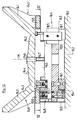
- 140 is the container or pot of a vibration conveyor designed as a spiral conveyor with respect to a vertical central axis TM.
- the pot 140 which is open at the top and flares upwards like a cone or funnel and is made, for example, of a suitable plastic, consists essentially of a peripheral wall 141 and a bottom 142 which is produced in one piece with this peripheral wall a conveying path 143 is formed, which extends helically around the vertical central axis TM of the pot from the inner surface of the bottom 142 to the upper, open edge of the pot 140 or the peripheral wall 141 and on which the inside of the pot 140 is taken up as an unordered quantity Components 144 are moved.
- the pot 140 With the flat underside of the bottom 142, the pot 140 is fastened to the upper side of a holding plate 145, and in the embodiment shown can be replaced interchangeably using a screw-type bolt (not shown) Connection or fastening element which can be screwed through a hole 146 in the bottom 142 into a threaded hole 147 of the holding plate 145.
- the holes 146 and 147 are provided coaxially with the axis TM.
- a leaf spring arrangement 148 is provided in each of three regions distributed uniformly about the axis TM, each of which in the embodiment shown is formed by two leaf spring packages, namely the leaf spring package 149 and the leaf spring package 150.
- Each leaf spring assembly consists of at least two leaf springs arranged one above the other.
- the upper ends of the leaf springs forming the leaf spring assembly 149 are connected to the holding plate 145 by means of a fastening block 151 fastened to the circular disk-shaped holding plate 145 and projecting radially with respect to the axis TM, using a fastening screw 152.
- the lower The ends of the leaf springs forming the leaf spring assembly 149 are connected to a holding block 154 by means of a fastening screw 153.
- the holding plate 145 is concentrically and circumferentially enclosed by a ring 155 on its circumference, the axis of which is coaxial with the axis TM.
- a fastening block 156 projecting beyond the underside of this ring is fastened to the ring 155, on which fastening bolts 157 hold the upper ends of the leaf springs forming the leaf spring assembly 150.
- the lower ends of the leaf springs forming the leaf spring assembly 150 are fastened to the holding block 154 by means of a fastening screw 158.
- each leaf spring assembly 148 the leaf springs are further arranged so that the leaf spring assemblies 149 and 150 are offset from one another in the circumferential direction of the ring 155. Furthermore, the leaf springs of these leaf spring assemblies are oriented in such a way that they lie with their larger surface sides in planes that run obliquely to the vertical, and with their narrow longitudinal sides that run between the upper and the lower end of each leaf spring, with respect to the axis TM, radially inside or radially outside are provided horizontally. As further shown in FIG. 14, the leaf spring assembly 149 is provided parallel to the leaf spring assembly 150 in each leaf spring assembly 148.
- a star-like support which is made in one piece with three arms 160, each of which is provided with its longitudinal extent running radially to the axis TM and being arranged uniformly distributed about this axis.
- the carrier 159 is located at a distance below the holding plate 145 and the ring 155 surrounding this holding plate.
- a holding block 154 is fastened to the free end of each arm 160, namely on the underside there.
- a base 161 preferably made of an elastic material, is fastened to the underside of each arm 160, with which the vibration conveyor can be fastened in a suitable manner to the top of a machine table 162.
- annular end wall 163 concentrically enclosing the axis TM is also fastened, which extends from the top of the machine table 142 to the underside of the ring 155, but both in the direction of the axis TM a distance from the top of the machine table 162 as well as a distance from the underside of the ring 155.
- the radial length of the arms 160 and the diameter of the circular cylindrical end wall 163 are selected so that this end wall with its outer surface is approximately flush with the outer surface of the ring 155 or slightly opposite this outer surface of the ring 155 lies radially inward.
- the end wall 163, which closes the space of the vibration conveyor below the holding plate 145 and the ring 155 to the outside of the leaf spring assemblies 148 as well as further elements to be described, is preferably in several parts, that is to say it consists of several segments and is detachable on the carrier 159 or the arms 160 attached so that the end wall 163 can be removed if necessary.
- Each electromagnetic drive 164 is provided at uniform angular intervals around the axis TM to generate the vibration or oscillation movement.
- Each drive 164 which is adjacent to an arm 160, but is angularly offset relative to the latter by a certain amount about the axis TM, consists of a magnetic core 166 having a magnetic coil 165, which is fastened to the underside of the outer ring 155.
- Each drive 164 provided below the holding plate 145 and below the ring 155 also has a magnet armature 167 which interacts with the magnet 165 or the magnetic core 166 and is fastened to the underside of the holding plate 145.
- the arrangement is such that a flat magnetic gap 168 with a predetermined width is formed between a surface of the magnetic core 166 and an adjacent surface of the magnet armature 167, which is in a plane parallel to the axis TM and to the longitudinal extension of the arm adjacent to the respective drive 164 160 lies.
- the arrangement is also such that the magnet armature 167 is closer to this arm 160 than the magnet core 166 provided with the magnet coil 165.
- the magnet coils 165 of the drives 164 are supplied with a changing current, preferably with a changing control unit (not shown in detail) Alternating current is applied so that each drive 164 exerts a reciprocating vibration force in an axial direction between the holding plate 145 and the ring 155 in a direction perpendicular to the plane of the magnetic gap 168.
- An auxiliary mass 170 consisting of several individual masses 169 is provided on the underside of the ring 155 between each drive 164 adjacent to an arm 160 and a further arm 160.
- these also consist of cuboid or plate-shaped individual masses 169 which are accommodated in the space enclosed by the end wall 163 and which are held by means of threaded bolts 171 projecting beyond the underside of the ring 155 with nuts 172.
- the individual masses are arranged and designed in such a way that their center of mass is as far out as possible with respect to the axis TM.
- auxiliary masses are provided radially on the outside in relation to the axis TM and, moreover, the threaded bolts 171 or their heads on the top of the ring 155 and also the nuts 172 are easily accessible, the end wall 163 or the one forming this end wall must be removed Segments a problem-free adjustment of the auxiliary masses or the moment of inertia of the counter-oscillating mass possible by removing or adding one or more individual masses.
- the auxiliary masses 170 in particular together with the ring 155 and with the other elements fastened to this ring, in particular the magnetic coils 165 and magnetic cores 166, form the counter-oscillating mass or a second oscillating element, while the holding plate 145 and the parts provided on this holding plate, in particular also the pot 141 form a first oscillating element or a useful mass.
- This useful mass and the counter-oscillating mass are coordinated with one another taking into account the spring constants of the leaf spring assemblies 149 and 150 of the leaf spring devices 148 so that when the drives 164 are switched on, practically no vibration forces on the carrier 159 and thus also be transferred to the machine table.
- the leaf spring assemblies 149 and 150 are each identical. This means that the moments of inertia formed by the two aforementioned masses are the same.
- auxiliary masses 170 consisting of the individual masses 169 and the hereby possible adjustment of the moments of inertia make it possible to use pots 140 of different shape, size and thus mass with one and the same vibration conveyor.
- a pot is shown with broken lines at 140 ', the bottom of its base also extending over the ring 155, that is to say covering this ring at the top.
- FIG. 16 shows, in a representation similar to FIG. 14, one of the at least three leaf spring devices 173 of a further possible embodiment of the vibratory spiral conveyor according to the invention.
- the leaf spring device 173 consists of the two leaf spring assemblies 174 and 175, each of which has a leaf spring 176a and a plurality of leaf springs 176b arranged one above the other in a packet or lamella-like manner.
- the leaf springs 176a and 176b of the leaf spring assembly 175 are fastened with their upper ends to the fastening block 151 of the holding plate 145.
- the leaf springs 176a and 176b of the leaf spring assembly 174 are attached with their upper ends to the holding block 176 of the ring 155.
- the leaf springs of the leaf spring assembly 175 are fastened to a holding block 177 and the leaf springs of the leaf spring assembly 174 are fastened to a holding block 178.
- the leaf spring device 173 not only two separate upper holding blocks 151 and 156 are provided, but also two separate lower holding blocks 177 and 178, the latter of which are suitably fastened to an arm 160 of the star-shaped carrier 159, again on the underside thereof Poor, in order to achieve the lowest possible design for the vibration conveyor or its vibration system with a sufficient length of the leaf springs 176a and 176b.
- the use of separate holding blocks 177 and 178 enables, among other things, all holding blocks identical for the lower and upper ends of the leaf springs 176a and 176b, so that the number of different parts required is significantly reduced.
- FIG. 16 shows, for fastening the leaf springs 176a and 176b in the holding blocks 177 and 178, but also in the holding blocks 151 and 156, instead of the fastening screws 152, 153, 157 and 158, threaded bolts 179 are provided.
- threaded bolts and locknuts 180 By means of these threaded bolts and locknuts 180, the leaf spring 176a of each leaf spring assembly 174 or 175 is held with its upper and with its lower end on the corresponding holding blocks, namely directly against these holding blocks.
- the leaf springs 176b of the leaf spring assemblies 174 and 175 are pushed onto the ends of the threaded bolts 179 projecting over the lock nuts 180 and fixed there by means of the nuts 181.
- This configuration offers the possibility of changing the spring constant of one or both leaf spring assemblies 174 and 175 by exchanging the outer leaf springs 176b for suitable leaf springs with other spring constants and / or changing the number of outer leaf springs 176b without the leaf springs 176a being released, i.e. without complete disassembly of the vibration system or without the connection between the individual elements of this vibration system and in particular the connection between the holding plate 145 or the ring 155 with the carrier 149 being lost.
- Fig. 17 shows a ring 155 'are used in place of the ring 155 about the axis TM 180 o offset regions has at least two one segment 182, an embodiment obtained by a freely accessible on the outside of the vibrating conveyor adjusting is adjustable radially to this axis, for example by means of an adjusting screw 183 in a plane perpendicular to the axis TM, in order in this way to achieve a comparison of the dynamic moment of inertia for the second oscillating element or for the counter mass.
- This adjustable segment 182 can be provided in addition to the auxiliary masses 170, so that in this case, by changing the auxiliary masses 170, it is possible to adjust the moment of inertia of the countermass in steps and by adjusting the segment 182 a continuous adjustment of the moment of inertia is possible.
- the counter-oscillating mass or the dynamic moment of inertia formed by this counter-oscillating mass, the useful mass or the dynamic moment of inertia formed by it and the associated spring elements or leaf spring assemblies 174 and 175 are selected so that at least the same natural frequency for both masses the leaf spring assemblies 175 for the largest pot 140 intended for use, ie have a sufficiently high number of leaf springs 176b for the pot 140 having the greatest moment of inertia.
- the adjustment is then carried out by reducing the number of leaf springs 176b in the leaf spring assemblies 175, in such a way that the natural frequency of the useful mass is again the same as the natural frequency of the counter-oscillating mass, despite a smaller pot or a pot with a smaller moment of inertia. At least in an area in which an adjustment is possible by changing the number of leaf springs 176b of the leaf spring assemblies 175, there is no change in the counter-oscillating mass or the associated leaf spring assemblies 174.
- the leaf springs 176b are preferably spaced apart from one another by intermediate plates 184 provided in the area of the threaded bolts 179, so that the leaf springs 176 are prevented from rubbing against one another when they swing. Similar intermediate plates can also be provided for the leaf spring assemblies 149 and 150.
Abstract
Description
Die Erfindung bezieht sich auf einen Vibrationsförderer gemäß Oberbegriff Patentanspruch 1 oder 9.The invention relates to a vibration conveyor according to the preamble of
Ein als Vibrationslängsförderer ausgebildeter Förderer dieser Art ist grundsätzlich bekannt (DD-PS 257 737).A conveyor of this type designed as a longitudinal vibratory conveyor is known in principle (DD-PS 257 737).
Vibrationslängsförderer werden insbesondere bei automatischen Fertigungsprozessen, d. h. bei Fertigungs- oder Montageautomaten für die Speicherung und Weitergabe von Werkstücken oder Bauteilen, insbesondere auch Kleinstbauteilen verwendet. Das Förderelement ist bei diesen Vibrationslängsförderern in den meisten Fällen eine Förderrinne, die dann an einem ersten, der Nutzmasse zugeordneten Schwingelement des Schwingsystems befestigt ist.Longitudinal vibration conveyors are used in particular in automatic manufacturing processes, i. H. used in manufacturing or assembly machines for the storage and transfer of workpieces or components, especially small components. The conveyor element in these longitudinal vibratory conveyors is in most cases a conveyor trough which is then attached to a first oscillating element of the oscillating system which is assigned to the useful mass.
Um eine Übertragung von Vibrationen auf einen Maschinentisch oder ein Maschinengestell, an dem der Vibrationslängsförderer vorgesehen ist, zu vermeiden und damit insbesondere auch Störungen anderer am Maschinentisch bzw. Maschinengestell ebenfalls vorgesehener Systeme durch solche Vibrationen zu vermeiden, ist bei dem Vibrationslängsförderer der eingangs genannten Art zusätzlich zur Nutzmasse ein eine Gegenmasse bildendes Schwingelement ebenfalls schwingend an einem Basiselement vorgesehen.In order to avoid the transmission of vibrations to a machine table or a machine frame on which the longitudinal vibration conveyor is provided, and thus in particular also to avoid disturbances of other systems also provided on the machine table or machine frame by such vibrations, the longitudinal vibration conveyor of the type mentioned at the outset is also required for the usable mass, an oscillating element forming a counter mass is also provided swinging on a base element.
Durch den Antrieb, der von einer von einem sich in der Amplitude ändernden stromdurchflossenen Magnetspule mit Magnetkern und einem zugeordneten Magnetanker gebildet ist, werden die beiden Schwingelemente bzw. die Nutzmasse und Gegenmasse gegenläufig in Schwingung bzw. Vibration versetzt, und zwar die zumindest Teil der Nutzmasse bildende Förderrinne in der Weise, daß sie eine hin- und hergehende Bewegung jausführt mit einer größeren, sich in Längsrichtung der Rinne erstreckenden Bewegungskomponente und mit einer kleineren, in vertikaler Richtung verlaufenden Bewegungskomponente. Die Bauelemente werden durch diese Vibrationsbewegung in Längsrichtung der Förderrinne, d. h. in Förderrichtung bewegt werden. Damit durch die Verwendung der Nutzmasse und Gegenmasse keine Vibrationskräfte auf das Basiselement und über dieses auf den Maschinentisch oder dergleichen Maschinengestell übertragen werden, ist es notwendig, daß (auch unter Berücksichtigung der Federkonstanten der Federeinrichtungen bzw. -elemente) die Nutzmasse und die Gegenmasse hinsichtlich ihres Massengewichtes exakt aufeinander abgestimmt sind (Massenabgleich). Die Nutzmasse ist zu einem Großteil von der Masse des Förderelementes gebildet, welches an den jeweiligen Anwendungsfall angepaßt ist und dessen Masse somit von Anwendungsfall zu Anwendungsfall unterschiedlich sein kann.The drive, which is formed by a magnet coil with a magnetic core and an associated magnet armature that changes in amplitude through its current, causes the two oscillating elements or the useful mass and counterweight to oscillate or vibrate in opposite directions, namely the at least part of the useful mass forming conveyor trough in such a way that it carries out a reciprocating movement with a larger movement component extending in the longitudinal direction of the trough and with a smaller movement component running in the vertical direction. The components are moved by this vibration movement in the longitudinal direction of the conveyor trough, ie in the conveying direction will. So that no vibration forces are transmitted to the base element and through this to the machine table or similar machine frame through the use of the useful mass and counter mass, it is necessary (also taking into account the spring constants of the spring devices or elements) the useful mass and the counter mass with regard to their Mass weight are exactly coordinated (mass comparison). The useful mass is largely formed by the mass of the conveying element, which is adapted to the respective application and the mass of which can therefore vary from application to application.
Für den Massenabgleich zwischen Nutzmasse und Gegenmasse setzt der bekannte Vibrationslängsförderer eine entsprechende Bearbeitung des Förderelementes voraus, wofür es dann erforderlich ist, daß Förderelement vom Schwingsystem abzunehmen, zu bearbeiten und erneut am Schwingsystem zu montieren. Da der Vibrationslängsförderer und insbesondere dessen Förderelement mit weiteren Elementen eines Systems zusammenwirken, ist es auch erforderlich, nach jeder erneuten Montage des Förderelementes dieses wiederum exakt in bezug auf die übrigen Elemente des Systems neu zu justieren. Dieser Arbeitsaufwand ist dann besonders groß, wenn das Förderelement mehrfach demontiert, bearbeitet und anschließend wieder montiert werden muß, bis der optimale Massenabgleich erreicht ist.For the mass comparison between useful mass and counter mass, the known longitudinal vibratory conveyor requires a corresponding processing of the conveying element, for which it is then necessary to remove the conveying element from the oscillating system, to process it and to mount it again on the oscillating system. Since the longitudinal vibration conveyor and in particular its conveying element cooperate with other elements of a system, it is also necessary to readjust it exactly with respect to the other elements of the system after each new installation of the conveying element. This workload is particularly great when the conveying element has to be dismantled several times, processed and then reassembled until the optimum mass balance has been achieved.
Bekannt ist auch ein Vibrationsförderer in Form eines Vibrationswendelförderers (DE-OS 39 40 111). Dieser bekannte Förderer hat den grundsätzlichen Vorteil, daß durch die spezielle Ausbildung des Schwingsystems eine weitestgehende vibrationsfreie Anordnung möglich ist, d.h. bei eingeschaltetem Vibrationsförderer Schwingungen auf einem Maschinengestell oder Maschinentisch nicht übertragen werden, die (Schwingungen) andere Funktionselemente eines Systems, beispielsweise einer Montagestrecke stören könnten.Also known is a vibration conveyor in the form of a vibratory bowl conveyor (DE-OS 39 40 111). This known conveyor has the basic advantage that a largely vibration-free arrangement is possible due to the special design of the vibration system, ie vibrations are not transmitted to a machine frame or machine table when the vibration conveyor is switched on, which (vibrations) could disrupt other functional elements of a system, for example an assembly line .
Nachteilig ist bei diesem bekannten Förderer u.a., daß insbes. das erste Schwingsystem fester Bestandteil eines Topfes ist, der betreffende Topf also nicht vom Schwingsystem abgenommen und/oder gegen einen anderen Topf ausgetauscht werden kann. Im bekannten Fall ist somit für jeden Topf, d.h. insbes. auf jede Topfgröße und Topfform ein ganz spezielles Schwingsystem vorgesehen.A disadvantage of this known conveyor is, among other things, that the first vibrating system in particular is an integral part of a pot, so the pot in question cannot be removed from the vibrating system and / or can be exchanged for another pot. In the known case, for each pot, i.e. In particular, a very special vibration system is provided for each pot size and shape.
Aufgabe der Erfindung ist es, einen Vibrationsförderer aufzuzeigen, der die vorgenannten Nachteile vermeidet, einen Massenabgleich bzw. ein Abgleich des Massenträgheitsmomentes einfach und ohne eine Demontage des Förderers oder des Förderelementes sowie eine flexiblere Verwendbarkeit ermöglicht.The object of the invention is to show a vibration conveyor which avoids the aforementioned disadvantages, enables mass balancing or balancing of the moment of inertia easily and without dismantling the conveyor or the conveying element, and more flexible usability.
Zur Lösung dieser Aufgabe ist ein Vibrationsförderer entsprechend dem kennzeichenden Teil des Patentanspruches 1 oder 9 ausgebildet.To solve this problem, a vibration conveyor is designed according to the characterizing part of
Nach einem Aspekt der Erfindung bildet das zweite Schwingelement wenigstens einen Teilbereich, der senkrecht zur Förderrichtung seitlich von dem Förderelement und/oder von dem ersten Schwingelement vorgesehen ist und an dem Mittel zum Befestigen einer mit in die Gegenmasse eingehenden Masse gebildet sind.According to one aspect of the invention, the second vibrating element forms at least one partial area, which is provided perpendicular to the conveying direction to the side of the conveying element and / or from the first vibrating element and on which means for attaching a mass that enters the counter mass are formed.
Bei einer bevorzugten Ausführungsform der Erfindung ist an diesem Teilbereich eine in ihrer Größe veränderbare Hilfsmasse frei zugänglich vorgesehen. Mit dieser Hilfsmasse kann dann ein Massenabgleich bzw. eine Massenkompensation bei Verwendung von Förderelementen mit unterschiedlicher Masse erfolgen. "Frei zugänglich" im Sinne der Erfindung bedeutet dabei, daß diese Hilfsmasse oder auch andere Elemente, die als frei zugänglich bezeichnet sind, so vorgesehen sind, daß für eine Änderung, für eine Einstellung bzw. für einen Abgleich keine Demontage des Förderelementes oder anderer Funktionselemente des Schwingsystems notwendig sind, ausgenommen selbstverständlich solche Elemente, die die Hilfsmasse bilden. Hiermit ist es möglich, bei funktionsfähigen Vibrationsförderer, d.h. insbesondere bei montiertem Förderelement einen Massenabgleich durchzuführen.In a preferred embodiment of the invention, an auxiliary mass which can be changed in size is freely accessible in this partial region. This auxiliary mass can then be used for mass balancing or mass compensation when using conveyor elements with different masses. "Freely accessible" in the sense of the invention means that this auxiliary mass or other elements, which are designated as freely accessible, are provided in such a way that no dismantling of the conveying element or other functional elements for a change, for an adjustment or for a comparison of the vibrating system are necessary, except, of course, those elements that make up the auxiliary mass form. This makes it possible to carry out mass balancing in the case of functional vibratory conveyors, ie in particular when the conveying element is installed.
Die jeweilige Hilfsmasse wird bei der Erfindung vorzugsweise von Einzelmassen gebildet, die entsprechend dem erforderlichen Massenabgleich entweder mit dem zweiten Schwingelement verbunden oder aber von diesem abgenommen werden. Damit bei einer vorgegebenen Änderung der Größe der Hilfsmasse ein Massenabgleich in einem möglichst großen Bereich erzielbar ist, ist bei dem erfindungsgemäßen Vibrationsförderer vorzugsweise dafür gesorgt, daß die Nutzmasse möglichst keine unnötigen Massenelemente aufweist, insbesondere auch das erste Schwingelement eine möglichst geringe Masse besitzt. Hierdurch ergibt sich dann eine relativ kleine Gegenmasse, so daß eine vorgegebene Änderung der Hilfsmasse eine relativ große Änderung der Gegenmasse insgesamt bewirken kann.In the case of the invention, the respective auxiliary mass is preferably formed from individual masses, which are either connected to the second oscillating element or removed from it in accordance with the required mass balance. So that a mass comparison can be achieved in the largest possible range with a predetermined change in the size of the auxiliary mass, the vibratory conveyor according to the invention preferably ensures that the useful mass has as few unnecessary mass elements as possible, and in particular that the first vibrating element has the smallest possible mass. This then results in a relatively small counter mass, so that a predetermined change in the auxiliary mass can bring about a relatively large change in the counter mass as a whole.
Bei einer Ausführung der Erfindung ist das zweite Schwingelement so ausgebildet, daß es beidseitig von dem Förderelement jeweils wenigstens einen Teilbereich zur Aufnahme jeweils wenigstens einer, frei zugänglichen Hilfsmasse aufweist.In one embodiment of the invention, the second oscillating element is designed such that it has at least one partial area on each side of the conveying element for receiving at least one freely accessible auxiliary mass.
Bei einer weiteren, bevorzugten Ausführungsform der Erfindung sind die beiden Schwingelemente beidseitig von einer die Förderrichtung einschließenden vertikalen Mittelebene voneinander beabstandet angeordnet. Bei an dem ersten Schwingelement bzw. auf dessen Oberseite befestigtem Förderelement bildet dann das zweite Schwingelement mit seiner Oberseite einen frei zugänglichen Bereich zum Befestigen der Hilfsmassen.In a further preferred embodiment of the invention, the two oscillating elements are arranged on both sides at a distance from one another from a vertical central plane including the conveying direction. When the conveying element is fastened to the first vibrating element or to the top thereof, the top of the second vibrating element then forms a freely accessible area for fastening the auxiliary masses.
Bei dieser Auführung ist es auch möglich, daß bei einem geteilten Förderelement, z.B. bei einer geteilten Förderrinne ein Teil dieses Förderelementes an dem ersten Schwingelement und ein anderes Teil dieses Förderelementes an dem zweiten Schwingelement befestigt wird, also das Förderelement selbst, d.h. dessen anderes Teil einen Teil der Hilfs- bzw. Gegenmasse bildet.With this arrangement it is also possible that in the case of a divided conveying element, for example in the case of a divided conveying trough, part of this conveying element on the first vibrating element and another part of this conveying element on the second Vibrating element is attached, that is, the conveying element itself, ie the other part of which forms part of the auxiliary or countermass.
Nach einem anderen Aspekt der Erfindung kann der Massenabgleich, d.h. die Kompensation der unterschiedlichen Masse verschiedener, mit dem Vibrationsförderer verwendeter Förderelemente auch dadurch erfolgen, daß zumindest ein Federelement der Nutzmasse oder eines die Nutzmasse einschließenden Schwingsystems derart veränderbar bzw. einstellbar ist, daß die Resonanz- oder Eigenfrequenz der Nutzmassse gleich oder in etwa gleich der Eigenfrequenz der Gegenmasse ist. Es erfolgt hier also eine Änderung der Federkonstanten wenigstens eines Federelementes der Nutzmasse und keine Änderung der Gegenmasse bzw. Hilfsmasse. Bevorzugt ist bei dieser Ausführung die Gegenmasse so gewählt, daß sie gleich der Nutzmasse dann ist, wenn von den für die Verwendung vorgesehenen unterschiedlichen Förderelementen dasjenige verwendet ist, welches die größte Masse aufweist. Dies bedeutet dann auch, daß bei Verwendung des Förderelementes mit der größten Masse die Federkonstanten der Federelemente der Nutz- und Gegenmasse gleich sind.According to another aspect of the invention, mass balancing, i.e. The compensation of the different masses of different conveying elements used with the vibration conveyor also takes place in that at least one spring element of the useful mass or an oscillating system including the useful mass can be changed or adjusted such that the resonance or natural frequency of the useful mass is equal to or approximately equal to the natural frequency the counter mass is. So there is a change in the spring constant of at least one spring element of the useful mass and no change in the counter mass or auxiliary mass. In this embodiment, the counter mass is preferably selected such that it is equal to the useful mass if the one of the different conveying elements intended for use is the one with the greatest mass. This also means that when the conveyor element with the largest mass is used, the spring constants of the spring elements of the useful and counter mass are the same.
Bevorzugt wird der Vibrationsförderer so betrieben, daß die Resonanz- oder Eigenfrequenz des Schwingungssystems, die eine Funktion der Masse bzw. Gegenmasse und der von den Federelementen erzeugten Federkonstanten ist, möglichst gleich der Frequenz des Antriebs, beispielsweise einer mit Netzfrequenz betriebenen Magnetanordnung ist. Um in diesem Sinne eine optimale Arbeitsweise zu ermöglichen, ist bei einer bevorzugten Ausführungsform der Erfindung auch ein Abgleich bzw. eine Anpassung der Federkonstanten möglich, und zwar ohne daß eine völlige Demontage des Schwingsystems notwendig ist. Hierfür bilden die Federelemente feste, die Elemente des Schwingsystems aneinander haltende Federelemente, sowie zusätzlich entfernbare und/oder austauschbare Federelemente.The vibration conveyor is preferably operated so that the resonance or natural frequency of the vibration system, which is a function of the mass or counter-mass and the spring constants generated by the spring elements, is as equal as possible to the frequency of the drive, for example a magnet arrangement operated at mains frequency. In order to enable an optimal way of working in this sense, in a preferred embodiment of the invention an adjustment or an adjustment of the spring constants is also possible, and without the complete disassembly of the vibration system being necessary. For this purpose, the spring elements form fixed spring elements which hold the elements of the vibration system together, and additionally removable and / or interchangeable spring elements.
In einer weiteren, grundsätzlichen Ausführungsform ist der Vibrationsförderer als Wendelförderer bzw. Vibrationswendelförderer ausgebildet. Bei diesem Förderer ist das die Förderstrecke bildende Element, welches vorzugsweise ein Topf ist, wiederum abnehmbar bzw. austauschbar am ersten Schwingelement vorgesehen. Durch die Änderung des Massenträgheitsmomentes der Gegenschwingmasse und/oder durch die Änderung der Federkonstanten der der Nutzmasse zugeordneten Federanordnungen bzw. deren Federelemente ist die Verwendung von Töpfen oder anderen, die Förderstrecke aufweisenden Elementen in sehr unterschiedlichen Größen, Formen, Massen möglich. Insbesondere ist es bei der erfindungsgemäßen Ausbildung nicht erforderlich, das Schwingsystem auf den jeweiligen Anwendungsfall zugeschnitten bzw. angepaßt gesondert herzustellen.In a further, basic embodiment, the vibration conveyor is designed as a spiral conveyor or vibratory spiral conveyor. In this conveyor, the element forming the conveyor path, which is preferably a pot, is again provided on the first oscillating element in a removable or replaceable manner. By changing the moment of inertia of the counter-oscillating mass and / or by changing the spring constants of the spring arrangements assigned to the useful mass or their spring elements, the use of pots or other elements having the conveying path in very different sizes, shapes, masses is possible. In particular, in the configuration according to the invention, it is not necessary to manufacture or adapt the vibration system to the respective application separately.
Bei dieser Ausführungsform der Erfindung erfolgt der zur Kompensation unterschiedlicher Größen von Töpfen usw. notwendige Abgleich durch eine Änderung des dynamischen Trägheitsmomentes der Gegenschwingmasse, und zwar durch eine Änderung der Masse (Massenabgleich) und/oder durch eine Änderung des Abstandes eines Massenelementes von der Mittelachse des Schwingsystems. Für den Massenabgleich sind dann wiederum Hilfsmassen frei zugänglich vorgesehen.In this embodiment of the invention, the adjustment necessary to compensate for different sizes of pots etc. takes place by changing the dynamic moment of inertia of the counter-oscillating mass, namely by changing the mass (mass comparison) and / or by changing the distance of a mass element from the central axis of the Vibration system. Auxiliary masses are then again freely accessible for mass balancing.
Damit mit einer vorgegebenen Änderung der Größe der Hilfsmassen ein Massenabgleich bzw. eine Änderung des Trägheitsmomentes in einem möglichst großen Bereich erzielbar sind, ist dafür gesorgt, daß die Nutzmasse möglichst keine unnötigen Massenelemente aufweist, insbes. auch das erste Schwingelement eine möglichst geringe Masse bzw. ein möglichst geringes Trägheitsmoment besitzt. Hierdurch ergibt sich dann auch eine relativ kleine Gegenschwingmasse, so daß eine bestimmte Änderung der Hilfsmassen eine relativ große Änderung der Gegenschwingmasse bzw. des Trägheitsmomentes insgesamt bewirken kann.So that a mass comparison or a change in the moment of inertia can be achieved in as large a range as possible with a predetermined change in the size of the auxiliary masses, it is ensured that the usable mass has as few unnecessary mass elements as possible, in particular also the first oscillating element has the smallest possible mass or has the lowest possible moment of inertia. This then also results in a relatively small counter-vibration mass, so that a certain change in the auxiliary masses can bring about a relatively large change in the counter-vibration mass or the moment of inertia as a whole.
Bei einer weiteren Ausführung des erfindungsgemäßen Vibrationswendelförderers erfolgt die Kompensation unterschiedlicher Größen bzw. Massen der verwendeten Töpfe nicht durch einen Massenabgleich, sondern zumindest in einem vorgegebenen Bereich durch Änderung bzw. Einstellung der Federcharakteristik bzw. Federkonstanten der der Nutzmasse zugeordneten Federanordnungen derart, daß bei dem jeweils verwendeten Topf die Eigenfrequenz der Nutzmasse gleich der Eigenfrequenz der Gegenschwingmasse ist. Das dynamische Trägheitsmoment der Gegenschwingmasse ist jeweils so gewählt, daß bei Verwendung des größten vorgesehenen Topfes, d.h. desjenigen Topfes der das größte dynamische Trägheitsmoment für die Nutzmasse bringt, das dynamische Trägheitsmoment der Nutzmasse gleich oder größer ist als das dynamische Trägheitsmoment der Schwingmasse. Hierdurch ist es möglich, die Federanordnungen zumindest für die Nutzmasse so auszubilden, daß sie bei dem größten Topf jeweils von einem Blattfederpaket mit einer Vielzahl von Blattfedern gebildet sind, so daß bei Verwendung eines kleineren Topfes eine Anpassung durch Entfernen einer oder mehreren Blattfedern möglich ist.In a further embodiment of the vibratory bowl feeder according to the invention, the different sizes or masses of the pots used are not compensated by mass balancing, but at least in a predetermined range by changing or adjusting the spring characteristics or spring constants of the spring arrangements assigned to the useful mass, such that in each case used pot the natural frequency of the useful mass is equal to the natural frequency of the counter-oscillating mass. The dynamic moment of inertia of the counter-oscillating mass is selected in such a way that when using the largest pot provided, i.e. of the pot that brings the greatest dynamic moment of inertia for the useful mass, the dynamic moment of inertia of the useful mass is equal to or greater than the dynamic moment of inertia of the vibrating mass. This makes it possible to design the spring arrangements at least for the useful mass so that they are each formed by a leaf spring assembly with a plurality of leaf springs in the largest pot, so that when a smaller pot is used, adaptation by removing one or more leaf springs is possible.
Unabhängig davon, ob zur Kompensation der jeweiligen Größe des verwendeten Topfes ein Abgleich durch Änderung des Trägheitsmomentes und/oder durch Änderung der Federcharakteristik erfolgt, wird der Vibrationswendelförderer bevorzugt so betrieben, daß die Resonanz- bzw. Eigenfrequenz des Schwingsystems, die eine Funktion des dynamischen Trägheitsmomentes unter Federcharakteristik in der Federkonstanten ist, möglichst gleich der Frequenz des Antriebes, beispielsweise der Netzfrequenz einer mit dieser Frequenz betriebenen Magnetanordnung ist. Eine in diesem Sinne optimale Arbeitsweise läßt sich auf jeden Fall durch einen Abgleich bzw. eine Anpassung der Federkonstanten erreichen.Regardless of whether a compensation by changing the moment of inertia and / or by changing the spring characteristic takes place to compensate for the respective size of the pot used, the vibratory bowl feeder is preferably operated so that the resonance or natural frequency of the vibration system, which is a function of the dynamic moment of inertia under spring characteristic in the spring constant is, if possible, equal to the frequency of the drive, for example the mains frequency of a magnet arrangement operated at this frequency. An optimal way of working in this sense can be achieved in any case by adjusting or adjusting the spring constants.
Bei einer bevorzugten Ausführungsform der Erfindung sind für eine Anpassung der Federcharakteristiken bzw. Federkonstanten feste Federelemente, die die Elemente des Schwingsystems aneinanderhalten, sowie zusätzlich entfernbare und/oder austauschbare Federelemente vorgesehen.In a preferred embodiment of the invention, fixed spring elements, which hold the elements of the vibration system together, and additionally removable and / or exchangeable spring elements are provided for adapting the spring characteristics or spring constants.
Weitere Ausführungen der Erfindung sind Gegenstand der Unteransprüche.Further embodiments of the invention are the subject of the dependent claims.
Die Erfindung wird im folgenden anhand der Figuren an Ausführungsbeispielen näher erläutert. Es zeigen:
- Fig. 1
- eine Vorder- bzw. Stirnansicht eines Vibrations-Längs-Förderers gemäß der Erfindung, und zwar in einer in der Achse der Förderrichtung verlaufenden Blickrichtung;
- Fig. 2
- einen Längsschnitt gemäß der Schnittlinie I-I der Fig. 1;
- Fig. 3
- einen Schnitt entsprechend der Linie II-II der Fig. 2;
- Fig. 4
- einen Schnitt entsprechend der Linie III-III der Fig. 1;
- Fig. 5
- in Seitenansicht eine weitere Ausführungsform des erfindungsgemäßen Vibrationsförderers;
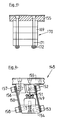
- Fig. 6
- eine Stirnansicht des Vibrationsförderers der Fig. 5 in Blickrichtung des Pfeiles B der Fig. 5;
- Fig. 7
- einen Schnitt entsprechend der Linie IV-IV der Fig. 5;
- Fig. 8
- einen Schnitt entsprechend der Linie V-V der Fig. 5;
- Fig. 9
- eine ähnliche Darstellung wie Fig. 8, jedoch bei einer weiteren Ausführungsform;
- Fig. 10
- in Detaildarstellung die Befestigung der Blattfedern einer austauschbaren Blattfederanordnung;
- Fig. 11
- in ähnlicher Darstellung wie Fig. 6 eine weitere Ausführungsform der Erfindung;
- Fig. 12
- in vereinfachter Darstellung und im Schnitt eine Ausführungsform des erfindungsgemäßen Vibrationsförderers in Form eines Wendelförderers;
- Fig. 13
- in vereinfachter Darstellung einen Schnitt entsprechend der Linie IV-IV der Fig. 12;
- Fig. 14
- in vereinfachter Teildarstellung eine der Blattfederanordnungen;
- Fig. 15
- in Einzeldarstellung eine der von mehreren Einzelmassen gebildeten anpaßbaren bzw. justierbaren Hilfsmassen des Vibrationsförderers nach Fig. 12;
- Fig. 16
- in ähnlicher Darstellung wie Fig. 14 eine weitere Ausführungsform des erfindungsgemäßen Vibrationsförderers;
- Fig. 17
- in vereinfachter schematischer Darstellung eine Draufsicht auf ein radial verstellbares Ringsegment eines die Hilfsmasse bildenden Ringes bei einer weiteren möglichen Ausführungsform.
- Fig. 1
- a front or end view of a longitudinal vibration conveyor according to the invention, in a direction extending in the axis of the conveying direction;
- Fig. 2
- a longitudinal section along the section line II of Fig. 1;
- Fig. 3
- a section along the line II-II of Fig. 2;
- Fig. 4
- a section along the line III-III of Fig. 1;
- Fig. 5
- in side view a further embodiment of the vibration conveyor according to the invention;
- Fig. 6
- an end view of the vibration conveyor of Figure 5 in the direction of arrow B of Fig. 5.
- Fig. 7
- a section along the line IV-IV of Fig. 5;
- Fig. 8
- a section along the line VV of Fig. 5;
- Fig. 9
- a representation similar to Figure 8, but in a further embodiment.
- Fig. 10
- in detail the attachment of the leaf springs of an interchangeable leaf spring arrangement;
- Fig. 11
- in a representation similar to FIG. 6, a further embodiment of the invention;
- Fig. 12
- in a simplified representation and in section an embodiment of the vibration conveyor according to the invention in the form of a spiral conveyor;
- Fig. 13
- in a simplified representation a section along the line IV-IV of Fig. 12;
- Fig. 14
- in a simplified partial representation of one of the leaf spring arrangements;
- Fig. 15
- in individual representation one of the adaptable or adjustable auxiliary masses of the vibration conveyor formed by several individual masses according to FIG. 12;
- Fig. 16
- in a representation similar to FIG. 14, another embodiment of the vibration conveyor according to the invention;
- Fig. 17
- in a simplified schematic representation a plan view of a radially adjustable ring segment of a ring forming the auxiliary mass in a further possible embodiment.
In den Figuren 1 bis 4 ist 1 eine Förderschiene oder Förderrinne, die eine geradlinige, im wesentlichen horizontale Förderstrecke des Vibrationslängsförderers für nicht näher dargestellte Klein-bzw. Kleinstbauteile bildet. Diese Förderrinne 1 ist an einem Vibrationsantrieb bzw. Schwingsystem 2 des Vibrationslängsförderers vorgesehen. Der Schwingsystem 2 ist seinerseits mittels einer Basisplatte 3 an einem Maschinengestell oder Maschinentisch 4 eines Fertigungsautomaten befestigt.In FIGS. 1 to 4, 1 is a conveyor rail or conveyor trough which forms a straight, essentially horizontal conveyor section of the longitudinal vibration conveyor for small or Small components. This
Durch das Schwingsystem 2 wird auf die Förderrinne 1 eine Vibrationsbewegung derart ausgeübt, daß sich die Bauteile in Richtung des Pfeiles A in Förderrinnenlängsrichtung bewegen.A vibration movement is exerted on the
An den beiden in Förderrichtung aufeinander folgenden und gegenüber der Vertikalen schräg verlaufenden stirnseitigen Enden der Basisplatte 3, d. h. bei der für die Fig. 2 gewählten Darstellung an dem linken sowie rechten Ende der Basisplatte 3 ist als Federelement jeweils ein von drei lamellenartig übereinander angeordneten Blattfedern 5 gebildetes Blattfederpaket befestigt, und zwar unter Verwendung zweier Befestigungsschrauben 6 und zweier Klemm- bzw. Halteplatten 7, die bei festgezogenen, in Gewinde der Basisplatte 3 eingreifenden Befestigungsschrauben 6 die Blattfedern 5 jedes Blattfederpaketes zwischen sich einspannen.At the two successive end ends of the
Wie insbesondere die Fig. 1 zeigt, weisen die jeweils gleichartig geformten und aus einem geeigneten Federblatt hergestellten Blattfedern jeweils einen im wesentlichen rechteckförmigen Zuschnitt auf. Die kürzeren Seiten dieses Zuschnitts sind in der Fig. 1 mit 5' und die längeren Seiten mit 5'' bezeichnet. Jede Blattfeder 5 ist ausgehend von der in der Fig. 1 oberen, kürzeren und in horizontaler Richtung angeordneten Seite 5' mit zwei parallel zu den längeren Seiten 5'' verlaufenden Schlitzen 8 versehen, die jeweils in gleichem Abstand von der in der Fig. 1 unteren, kürzeren Seite 5' des Zuschnittes enden, und zwar in einem Abstand, der etwa der Breite der rechteckförmigen Klemmplatten 7 entspricht. Durch die beiden Schlitze 8 sind die Blattfedern 5 jeweils doppelt geschlitzt und bilden drei durch die Schlitze 8 voneinander getrennte Zungen 9 und 10, die am geschlossenen Ende der Schlitze 8 durch den nicht geschlitzten Bereich 11 der betreffenden Blattfeder 5 einstückig miteinander verbunden sind. Wie die Fig. 1 weiterhin auch zeigt, besitzt die mittlere Zunge 10 in Richtung senkrecht zu den Schlitzen 8, d. h. in einer Achsrichtung parallel zu den kürzeren Seiten 5' eine Breite, die doppelt so groß ist wie die entsprechende Breite eine äußeren Zunge 9, d. h. die Summe der Breiten der beiden äußeren Zungen 9 ist gleich der Breite der mittleren Zunge 10.As shown in particular in FIG. 1, the leaf springs, each of the same shape and made from a suitable spring leaf, each have an essentially rectangular cut. The shorter sides of this blank are designated 5 'in FIG. 1 and the longer sides 5''. Starting from the upper, shorter and horizontally arranged side 5 'in FIG. 1, each
Im Abschnitt 11 sind auf einer Achse parallel zu der kürzeren Seite 5' Bohrungen 12 für die Befestigungsschrauben 6 vorgesehen. Die mittlere Zunge 10 besitzt an ihrem freien, d. h. dem Abschnitt 11 entfernt liegenden Ende zwei Bohrungen 13 und die beiden äußeren Zungen 9 jeweils eine Bohrung 13. Diese Bohrungen liegen wiederum auf einer gemeinsamen Linie parallel zu den kürzeren Seiten 5'.In
Es versteht sich, daß die Blattfedern 5 jedes Blattfederpaketes in gleicher Orientierung und bezüglich der Schlitze 8 und Bohrungen 12 bzw. 13 deckungsgleich übereinander angeordnet sind.It is understood that the
Die mittleren Zungen 10 der Blattfedern 5 der Blattfederpakete sind jeweils mit Hilfe von den Bohrungen 13 durchgreifenden Befestigungsschrauben 14 an den stirnseitigen, gegenüber der vertikalen abgeschrägten Enden eines aus Leichtmetall hergestellten Schwingelementes 15 befestigt. Dieses Schwingelement 15 ist im wesentlichen ein langgestreckter, mit seiner Achse in Förderrichtung A orientierter quaderförmiger Körper, der in einer Querschnittsebene senkrecht zur Förderrichtung A einen rechteckförmigen Querschnitt aufweist (Fig. 4) und im Bereich eines Endes mit einem über die untere Querschnittsseite vorstehenden Vorsprung 16 versehen ist.The
Die freien Enden der Zungen 9 sind mit Hilfe von die dortigen Bohrungen 13 durchgreifenden Befestigungsschrauben 17 jeweils an einem Halteklotz 18, und zwar an einer gegenüber der vertikalen schräg verlaufenden Fläche dieses Halteklotzes 18 befestigt. Die Halteklötze 18, von denen insgesamt vier vorgesehen sind, sind ihrerseits an der Oberseite eines plattenförmigen, d. h. eines als rechteckförmige Platte ausgebildeten Schwingelementes 19 befestigt, und zwar derart, daß jeder Halteklotz 18 über die horizontale Oberseite dieses plattenförmigen Schwingelementes 19 vorsteht. Durch die Befestigung der von den Blattfedern 5 gebildeten Blattfederpaketen an gegenüber der Vertikalen geneigten Fläche sowohl an der Basisplatte 3 als auch an dem Schwingelement 15 und den Halteklötzen 18 weisen die Blattfedern 5 bzw. die von diesen gebildeten Blattfederpakete eine Neigung gegenüber der Vertikalen bzw. gegenüber einer senkrecht zur Förderrichtung verlaufenden vertikalen Ebene auf, d. h. ausgehend von der oberen Seite 5' schließen die Blattfedern 5 einen winkel kleiner als 90o mit der Achse der Förderrichtung ein, der sich in Förderrichtung öffnet, wie dies für eine die Bauteile in Förderrichtung A bewegende Vibrationsbewegung notwendig ist.The free ends of the
Wie die Figuren zeigen, ist das plattenförmige Schwingelement 19 mit gewissem Abstand unterhalb des Schwingelementes 15 angeordnet und besitzt im Bereich der einen Stirnseite des Schwingsystems 2, d. h. bei der für die Fig. 2 gewählten Darstellung im Bereich des dortigen linken Endes eine zu diesem Ende hin offene Ausnehmung 20, durch die der Vorsprung 16 hindurchreicht, und zwar derart, daß dieser Vorsprung auch im Bereich der Ausnehmung 20 im Bereich aller seiner Flächen von dem Schwingelement 19 beabstandet ist und der Vorsprung 16 mit seinem freien Ende relativ weit über die Unterseite des im wesentlichen als rechteckförmige Platte ausgebildeten Schwingelementes 19 vorsteht. An diesem unteren Ende ist am Vorsprung 16 ein als Magnetanker dienender Klotz 21 aus ferromagnetischem Material, d. h. aus Stahl befestigt.As the figures show, the plate-shaped
Die Figuren zeigen weiterhin, daß das Schwingelement 19 senkrecht bzw. quer zur Förderrichtung A beidseitig über das Schwingelement 15 wegsteht und an diesen überstehenden Bereichen auch jeweils die Halteklötze 18 befestigt sind, und zwar derart, daß sich diese beidseitig von dem Schwingelement 15 befinden, jedoch jeweils in einem vorgegebenen Abstand von dem Schwingelement 15. Das Schwingelement 19 liegt mit seinen längeren Seiten parallel zur Förderrichtung A und mit seinen kürzeren Seiten senkrecht zu dieser Förderrichtung.The figures further show that the
An der Unterseite des Schwingelementes 19 sind ein aus einem ferromagnetischen Material, z. B. aus Stahl hergestellter Magnetkern 22 sowie eine diesen Kern umschließende Magnetspule 23 vorgesehen. Eine plane Stirnseite des Magnetkernes 22, der mit seiner von den Windungen der Magnetspule 23 im wesentlichen konzentrisch umschlossenen Längsachse parallel zur Förderrichtung A liegt, ist in einem vorgegebenen Abstand einer ebenen Fläche des Magnetankers 21 gegenüberliegend angeordnet. Dieser Abstand entspricht einem Magnet- oder Luftspalt.At the bottom of the vibrating
Im Bereich der beiden, in Förderrichtung A aufeinander folgenden Enden, d. h. im Bereich des in der Fig. 2 linken und in dieser Figur rechten Endes des Schwingelementes 15 ist an diesem Schwingelement jeweils ein U-förmiger Haltebock 24 befestigt, der einen sich quer zur Förderrichtung A erstreckenden Abschnitt 25 aufweist, mit dessen Unterseite der jeweilige Haltebock 24 an der Oberseite des Schwingelementes 15 befestigt ist. An den beiden Enden ist der quaderförmige Abschnitt 25 einstückig mit jeweils einem Vorsprung 26 versehen. Die beiden Vorsprünge 26 und der Abschnitt 25 bilden die nach oben hin offene U-Form des jeweiligen Bockes 24. Zwischen den beiden Vorsprüngen 26 jedes Haltebockes 24, die an ihren einander zugewandten Seiten einen Abstand aufweisen, der größer ist als die äußere Breite der Förderrinne 1, ist diese Förderrinne gehalten und mit dem Schwingelement 15 verbunden. Hierfür ist in einem Gewinde jedes Vorsprunges 26 eine Maden- bzw. Einstellschraube 27 mit Kontermutter 28 derart vorgesehen, daß diese Einstellschraube 27 mit ihrer Achse parallel zur Längserstreckung des Abschnittes 25, d. h. in horizontaler Richtung und senkrecht zur Förderrichtung A liegt. Die Kontermutter 28 befindet sich jeweils an der der Führungsrinne 1 abgewandten Außenseite des betreffenden Vorsprunges 26. Mit einem über die der Förderrinne 1 zugewandte Innenseite des jeweiligen Vorsprungs 26 vorstehenden Ende bildet jede Einstellschraube 27 einen gegen eine Längsseite der Förderrinne 1 anliegenden einstellbaren Anschlag.In the region of the two ends which follow one another in the conveying direction A, i. H. In the area of the left end of the
Durch Verdrehen der Einstellschraube 27, von denen insgesamt vier vorgesehen sind, kann die Lage bzw. Orientierung der Förderrinne 1 in bezug auf das Schwingelement 15 und damit in bezug auf den Schwingsystem 2 insgesamt eingestellt werden.By turning the adjusting
Die einmal getroffene Einstellung wird durch Anziehen der Kontermuttern 28 festgelegt, so daß auch nach einem eventuellen Abnehmen der Förderrinne 1, z. B. für Reparaturzwecke oder für eine Nachbearbeitung, die Förderrinne 1 ohne die Notwendigkeit einer erneuten Einstellung durch Einsetzen in die Halteböcke 24 am Schwingsystem 2 in der richtigen Orientierung wieder befestigt werden kann. Zur endgültigen Verriegelung dienen mit Langlöchern versehene Verriegelungsplatten 29, von denen jeweils eine an der Oberseite dieses Vorsprunges 26 vorgesehen, d. h. mittels einer Befestigungsschraube 30 gehalten ist. Bei am Schwingsystem 2 bzw. am Schwingelement 15 befestigter Führungsrinne greift die Verriegelungsplatten 29 jeweils bei festgezogenen Befestigungsschrauben 30 seitlich in Nuten 31 der Förderrinne 1 ein.The setting once made is determined by tightening the
Das Schwingelement 15 und die Förderrinne 1 sowie alle mit dem Schwingelement 15 und/oder der Förderrinne 1 verbundenen Teile bilden die Nutzmasse des Schwingsystemes 2 und das Schwingelement 19 mit allen an diesen Elementen vorgesehenen Teilen, insbesondere mit dem Magnetkern 22 und der relativ schweren Magnetspule 23, aber auch mit den Halteklötzen 18 die Gegenmasse des Schwingsystems. Die Nutzmasse und die Gegenmasse sind dabei mit ihren Massenschwerpunkten auf einer Linie angeordnet sind, die im wesentlichen in einer sich in Förderrichtung A erstreckenden vertikalen Ebene liegt. Die beiden Massen sind weiterhin so aufeinander abgestimmt, daß bei eingeschalteter Magnetspule 23, d. h. mit einem Wechselstrom beaufschlagter Magnetspule 23 beide Massen relativ und gegenläufig zueinander unter elastischer Verformung der Blattfedern 5 bzw. deren Zunge 9 und 10 schwingen, ohne daß Vibrationsbewegungen auf die Basisplatte 3 und damit auf den Maschinentisch 4 übertragen werden. Dieser Idealzustand ist bei der dargestellten Ausführungsform, bei der die von der Zunge 10 und zwei Zungen 9 gebildete Federkonstante jeweils gleich groß ist, dann erreicht, wenn die Gegenmasse und die Nutzmasse gleich groß sind. Um dies insbesondere auch bei Förderrinnen 1 unterschiedlicher Masse zu erreichen, ist an der Oberseite des plattenförmigen Schwingelementes 19, und zwar im Bereich der beiden Längsseiten dieses Schwingelementes zwischen jeweils zwei Halteklötzen 18 eine in ihrer Größe veränderbare Hilfsmasse 32 vorgesehen.The
Jede der beiden Hilfsmassen 32 besteht jeweils aus einer oder mehreren plattenartigen Einzelmassen 33 aus Metall bzw. Stahl, die mit Hilfe von Schrauben 34 zu der Hilfsmasse miteinander verbunden und an dem Schwingelement 19 der Gegenmasse gehalten sind. Da dieses Schwingelement außen liegt, d. h. zugänglich ist, können die beiden Hilfsmassen 32 durch Entfernen einer oder mehrerer Hilfsmassen 33 bzw. umgekehrt durch Hinzufügen einer oder mehrerer Hilfsmassen 33 so eingestellt werden, daß eine optimale Anpassung der Nutzmasse und der Gegenmasse erreicht ist. Um eine wirksame Einstellung der Gegenmasse durch Änderung der Hilfsmasse zu erreichen, ist es bei der dargestellten Ausführung auch wesentlich, daß die Nutzmasse möglichst klein gehalten ist, d. h. insbesondere auch der in die Nutzmasse mit eingehende Teil des Schwingsystems 2 keine unnötigen Massenelemente aufweist und auch das Schwingelement 15 aus einem Material mit geringem spezifischem Gewicht bzw. spezifischer Masse hergestellt ist, daß entsprechend die Gegenmasse klein gehalten werden kann. Insbesondere ist hier auch wesentlich, daß Elemente mit hoher Masse, insbesondere der Magnetkern 22 und die Magnetspule 23 an dem die Gegenmasse bildenden Schwingelement 19 befestigt sind.Each of the two
Die Einzelmassen 33 sind bei der dargestellten Ausführungsform jeweils gleichartig ausgebildet. Grundsätzlich ist es selbstverständlich auch möglich, schwerere und leichtere Einzelmassen 33 vorzusehen, um so eine sehr exakte Anpassung der Gegenmasse an die hauptsächlich auch von der Förderrinne 1 und von dort vorgesehenen Funktionselementen bestimmten Nutzmasse in kleinen Schritten zu ermöglichen. Da bei dem erfindungsgemäßen Vibrationslängsförderer das der Nutzmasse zugeordnete Schwingelement 15 innen liegend und das der Gegenmasse zugeordnete Schwingelement 19 außen liegend vorgesehen sind, d. h. das der Gegenmasse zugeordnete Schwingelement 19 quer zur Förderrichtung A beidseitig über das Schwingelement 15 vorsteht und dort die Hilfsmassen 32 vorgesehen sind, ist die vorbeschriebene Massenanpassung unter Verwendung der Einzelmassen 33 insbesondere auch bei am Maschinentisch 4 montiertem Vibrationslängsförderer möglich, d. h. der Vibrationslängsförderer muß zur Massenanpassung nicht vom Maschinentisch 4 demontiert werden.The
Da das der Gegenmasse zugeordnete Schwingelement 19 in der vorbeschriebenen Weise außen liegend vorgesehen ist, ist es auch möglich, einen Halteklotz 35, der an der Unterseite des Schwingelementes 19 vorgesehen ist und den Magnetkern 22 mit der Magnetspule 23 trägt, mit Befestigungsschrauben 36 an dem Schwingelement 19 zu befestigen, die jeweils an den seitlich über das Schwingelement 15 wegstehenden Bereichen des Schwingelementes 19, d. h. im Bereich der Längsseiten dieses Schwingelementes vorgesehen und somit (nach dem Abnehmen der Hilfsmassen 32) von oben her frei zugänglich sind. Bei der dargestellten Ausführungsform sind insgesamt zwei Befestigungsschrauben 36 vorgesehen, und zwar jeweils eine Befestigungsschraube im Bereich jeder Längsseite des Schwingelementes 19. Die Befestigungsschrauben 36 greifen durch Bohrungen 37 des Schwingelementes 19 hindurch in Gewindebohrungen des Halteklotzes 35. Die Bohrungen 37 besitzen insbesondere in Förderrichtung A einen Querschnitt, der größer ist als der Außendurchmesser der Befestigungsschrauben 36, so daß eine Einstellung des Halteklotzes 35 mit dem Magnetkern 22 und der Magnetspule 23 nicht nur relativ zum Schwingelement 19, sondern auch relativ zum Schwingelement 15 bzw. zu dem dort vorgesehenen Magnetanker 21 und damit eine Einstellung des Magnet- bzw. Luftspaltes zwischen dem Magnetanker 21 und dem Magnetkern 22 von außen her frei möglich ist, und zwar ebenfalls wiederum ohne die Notwendigkeit einer Demontage des Vibrationslängsförderers vom Maschinentisch 4.Since the
Eine optimale Einstellung des Magnet- bzw. Luftspaltes zwischen dem Magnetanker 1 und dem Magnetkern 22 ist unerläßlich, um einerseits eine Relativbewegung zwischen dem Magnetanker 21 und dem Magnetkern 22 bzw. die gegenläufige Schwingbewegung zwischen der Nutzmasse und Gegenmasse ohne ein Einschlagen zwischen Magnetanker 21 und Magnetkern 22 zu ermöglichen, und um andererseits den Magnet- bzw. Luftspalt so klein wie nur irgend möglich zu halten. Ein zu großer Luft- bzw. Magnetspalt würde einen zu geringen Magnetfluß bzw. eine zu geringe elektrische Induktivität für die Magnetspule 23 und damit einen zu hohen, die Magnetspule möglicherweise zerstörenden Strom bedeuten.An optimal setting of the magnet or air gap between the
Wie insbesondere aus den Figuren 1, 3 und 4 ersichtlich ist, sind an den beiden parallel zur Förderrichtung A verlaufenden Längsseiten der langgestreckten Basisplatte 3 noch zwei Blenden oder Wandelemente 38 mit Hilfe von Befestigungsschrauben 39 abnehmbar befestigt. Jedes Wandelement 38 reicht mit seiner oberen, im wesentlichen parallel zur Förderrichtung A verlaufenden horizontalen Seite 38' bis in die Nähe der Unterseite des plattenförmigen Schwingelementes 19, wobei selbstverständlich ein die Schwingbewegung ermöglichender Spalt zwischen dieser Seite 38' und der Unterseite des Schwingelementes 19 verbleibt. Wie aus den Figuren auch ersichtlich ist, steht das Schwingelement 19 mit seinen beiden Längsseiten geringfügig über die Außenfläche des jeweiligen Wandelementes 38 vor. Die beiden Wandelemente 38 erstrecken sich weiterhin bis an die beiden, die Blattfedern 5 tragenden Stirnseiten der Basisplatte 3. Die dortigen kürzeren Seiten 38'', die im Abstand von dem jeweiligen Blattfederpaket vorgesehen sind, verlaufen schräg zur Vertikalen, d. h. parallel zu den Blattfedern des jeweils benachbarten Blattfederpaketes.As can be seen in particular from FIGS. 1, 3 and 4, two diaphragms or
In den Fig. 5 bis 8 ist eine weitere Ausführung eines Vibrationsförderers gemäß der Erfindung dargestellt. Dieser Vibrationsförderer besteht aus einem am Maschinentisch 4 oder an einem anderen Tragelement oder Konsole befestigten Basisplatte 40, welche Teil eines Schwingsystems 41 ist. Dieses Schwingsystem besitzt neben der Basisplatte 40 zwei Schwingelemente 41 und 42, die aus einem geeigneten Metall mit möglichst geringem spezifischen Gewicht, beispielsweise aus einer Aluminiumlegierung hergestellt sind und hinsichtlich ihrer Formgebung jeweils im wesentlichen einen sich in der Achse der Förderrichtung A erstreckenden Jochabschnit 42' bzw. 43', der sich jeweils mit Abstand oberhalb der Basisplatte 40 befindet, sowie einen sich von diesem Jochabschnitt in vertikaler Richtung nach unten erstreckenden Schenkel 42'' bzw. 43'' aufweisen.5 to 8 a further embodiment of a vibration conveyor according to the invention is shown. This vibration conveyor consists of a
Wie die Fig. zeigen, sind die beiden Schwenkelelemente 42 und 43 quer zur Förderrichtung A nebeneinander und voneinander beabstandet vorgesehen, und zwar beidseitig von einer vertikalen, die Förderrichtung A einschließenden Mittelebene. Über zwei jeweils mehrere Blattfedern 44 aufweisende Blattfederpakete 45 und 46 sind die beiden Schwingelemente 42 und 43 mit der Basisplatte 40 verbunden. Die horizontale Breite der Basisplatte 40 senkrecht zur Förderrichtung A ist in etwa gleich der entsprechenden Breite der von den beiden Schwingelementen 42 und 43 gebildeten Anordnung. Die Blattfedern 44 sind jeweils so ausgebildet, daß jede Blattfeder 44 durch eine mittlere Schlitzung 47 zwei hinsichtlich ihrer Formgebung gleiche Zungen 48 und 49 bildet, die im unteren Bereich der jeweiligen Blattfeder 44 durch einen durchgehenden Abschnitt 44' miteinander verbunden sind. Die Zunge 48 jeder Blattfeder 44 ist mittels zweier Befestigungsschreiben 50 an dem in der Fig. 5 linken bzw. rechten Ende des Jochabschnittes 42' und die Zunge 49 jeder Blattfeder 44 mittels zweier Schrauben 50 an dem in der Fig. 5 linken bzw. rechten Ende des Jochabschnittes 43' befestigt. Im Bereich des durchgehenden Abschnittes 44' sind die Blattfedern 44 unter Verwendung von Schrauben 50 und Unterlegblechen 51 an der Basisplatte 40 bzw. an dort über die Oberseite wegstehenden Nasen 40' befestigt. Wie die Figuren zeigen, sind die bei der dargestellten Ausführungsform jeweils zwei Blattfedern 44 aufweisenden Blattfederanordnungen bzw. Pakete 45 und 46 gegenüber der Vertikalen wieder geneigt.As shown in the figures, the two
Wie die Figuren weiterhin zeigen, ist der Schenkel 42'' in Förderrichtung A gegenüber dem Schenkel 43'' versetzt, d.h. der Schenkel 42'' befindet sich an dem in der Fig. 5 linken, bezogen auf die Förderrichtung A vorderen Ende und der Schenkel 43'' an dem in der Fig. 5 rechten, bezogen auf die Förderrichtung A hinteren Ende des Schwingsystems 41. Am Schenkel 43'' ist die Magnetspule 52 befestigt, und zwar derart, daß diese Magnetspule innerhalb des zwischen den beiden Schenkeln 42'' und 43'' gebildeten Raumes unterhalb der Jochabschnitte 42' und 43' angeordnet ist. Am Schenkel 42'' ist ein mit der Magnetspule 52 zusammenwirkender Magnetanker 53 befestigt. Zwischen dem Eisenkern der Magnetspule 52 und dem Magnetanker 53 ist wiederum der Magnetspalt mit vorgegebener Breite gebildet, und zwar in einer senkrecht zur Förderrichtung A verlaufenden vertikalen Ebene.As the figures further show, the
Bei der dargestellten Ausführungsform bildet das Schwingelement 42 Teil der Nutzmasse, d.h. auf diesem Schwingelement ist die Förderschiene bzw. Förderrinne 1 befestigt, und zwar mit Hilfe eines Befestigungswinkels 54, der mit seinem einen horizontalen Schenkel 54' an die Unterseite der Förderrinne 1 angeschraubt ist und mit seinem vertikalen anderen Schenkel 54'' in eine seitliche Ausnehmung des Jochabschnittes 42' eingreift und dort mittels Schrauben 55 festgelegt ist. Für die Schrauben 55 besitzt der Befestigungswinkel 54 bzw. dessen Schenkel 54'' Schlitze 56, die zu der dem Schenkel 54' entfernt liegenden Kante des Schenkels 54'' hin offen sind. Hierdurch ist es möglich, die Förderrinne 1 nach dem Lösen der Schrauben 55 vom Schwingelement 42 nach oben abzuheben und wieder auf das Schwingelement 42 aufzusetzen, wobei sämtliche Einstellungen insbesondere am Vibrationsförderer sowie bezüglich der Zuordnung dieses Vibrationsförderers und der Förderrinne 1 zu anderen Elementen eines Gesamt-Systems erhalten bleiben.In the illustrated embodiment, the vibrating
Das Schwingelement 43 bildet bei der dargestellten Ausführungsform Teil der Gegenmasse, d.h. an dem Schwingelemnt 43 bzw. auf der Oberseite des Jochabschnittes 43' ist seitlich von der Förderrille 1 mit Hilfe eines Befestigungswinkels 54 die wiederum aus mehreren Einzelmassen bestehende Hilfsmasse 57 vorgesehen.In the embodiment shown, the vibrating
Die Besonderheit der in den Fig. 5 bis 8 dargestellten Ausführung bzw. des dortigen Schwingsystems 41 besteht darin, daß das Schwingelement 42 mit der Förderrinne 1 und das Schwingelement 43 mit der Hilfsmasse 57 beidseitig von einer vertikalen, die Förderrichtung A einschließenden Mittelebene vorgesehen sind. Hierdurch ergibt sich insbesondere eine sehr einfache Formgebung für die Schwingelemente 42 und 43, und zwar trotz der Möglichkeit eines einfachen Massenabgleichs durch entsprechende Wahl der Hilfsmasse 57 bzw. der Einzelmassen (Trimmgewichte).The special feature of the embodiment shown in FIGS. 5 to 8 and the
Wie die Fig. 9 zeigt, besteht grundsätzlich die Möglichkeit, bei Förderung bestimmter, z. B. besonders breiter Bauelemente 58 beide Schwingelemente 42 und 43 für die Bewegung dieser Bauelemente 58 zu nutzen. In diesem Fall wird dann anstelle der Förderrinne 1 eine geteilte Förderrinne 59 verwendet, die bei der dargestellten Ausführungsform einen im wesentlichen C-förmigen und an der Oberseite offenen Querschnitt besitzt und aus den beiden Elementen 59' und 59'' besteht. Jedes dieser Elemente ist in geeigneter Weise an der Oberseite eines Schwingelementes 42 bzw. 43 befestigt. Bei eingeschalteter, mit Wechselstrom betriebener Magnetspule 52 bewegen sich dann entsprechend den Schwingelementen 42 und 43 auch die beiden Elemente 59' und 59'' der Förderrinne oder -schiene 59 gegenläufig, so daß insgesamt auf die Bauelemente 58 eine Förderwirkung in Richtung des Pfeiles A der Fig. 5 ausgeübt wird, d.h. sich diese Bauelemente 58 in Förderrichtung bewegen. Durch entsprechende Wahl der Masse der Elemente 59' und 59'' und/oder durch einen zusätzlichen Massenabgleich wird wiederum dafür gesorgt, daß die Nutzmasse und der Gegenmasse gleich bzw. in etwa gleich sind, und zwar bei gleicher Federkonstanten der Zungen 48 und 49.As Fig. 9 shows, there is basically the possibility, with the promotion of certain, for. B. particularly wide components 58 to use both vibrating
Um bei möglichst geringer Stromaufnahme der Magnetspule 52 eine optimale Förderwirkung zu erreichen, ist es sinnvoll, das jeweilige Schwingsystem 41 in der Nähe seiner mechanischen, d.h. durch die Massen und die Federkonstanten der Blattfedern 44 bzw. der Blattfederpakete 45 und 46 bestimmten Resonanz zu betreiben. Insbesondere dann, wenn Förderschienen oder -rinnen 1 bzw. 59 mit sehr unterschiedlicher Masse zusammen mit ein und demselben Schwingsystem 41 verwendet werden sollen und aus diesem Grunde ein Massenabgleich in einem relativ großen Bereich erforderlich ist, kann es notwendig, zumindest jedoch zweckmäßig sein, durch Austausch der Blattfedern 44 und/oder durch Änderung der Anzahl dieser Blattfedern die Federkonstante an die geänderte Masse anzupassen.In order to achieve an optimal conveying effect with the lowest possible current consumption of the
Um bei einem solchen Austausch der Blattfedern und/oder bei einer Änderung der Anzahl der Blattfedern nicht das gesamte Schwingsystem demontieren zu müssen bzw. dafür zu sorgen, daß die Befestigung der Schwingelemente 42 und 43 an der Basisplatte 40 erhalten bleibt, kann entsprechend der Fig. 10 bei jeder Blattfederanordnung 45 und 46 eine Blattfeder 44a vorgesehen sein, die auf jeden Fall fest mit der Basisplatte 40 und den Schwingelementen 42 bzw. 43 verbunden ist. Zusätzlich zu dieser Blattfeder 44a sind dann weitere, abnehmbare bzw. austauschbare Blattfedern 44b vorgesehen. Anstelle der Schrauben 50 sind Gewindebolzn 60 verwendet, an denen die festen, d.h. nicht austauschbaren Blattfedern 44a mit Hilfe von Konter-Muttern 61 festgelegt sind. Zum Festlegen der austauschbaren Blattfedern 44b dienen die Muttern 62.In order not to have to disassemble the entire oscillating system or to ensure that the attachment of the
Selbstverständlich kann eine ähnliche Ausbildung auch bei den Blattfedern 5 des Schwingsystems 2 verwendet sein.Of course, a similar design can also be used for the
Bei der vorstehenden Beschreibung wurde davon ausgegangen, daß jeweils ein Massenabgleich erfolgt, und zwar derart, daß Nutzmasse und Gegenmasse gleich oder in etwa gleich sind, wobei durch Austausch der Blattfedern zusätzlich auch die Federkonstanten für die Nutzmasse und Gegenmasse derart eingestellt werden, daß sich für die beiden Schwingelemente eine Eigenfrequenz ergibt, die möglichst gleich der Frequenz des Antriebs ist.In the above description, it was assumed that a mass comparison is carried out in such a way that the usable mass and counterweight are the same or approximately the same, and by replacing the leaf springs, the spring constants for the usable mass and counterweight are also set such that the two vibrating elements results in a natural frequency that is as equal as possible to the frequency of the drive.
In der Fig. 11 ist ein Vibrationsförderer dargestellt, bei dem eine Kompensation des Schwingsystems bei Förderrinnen 1 mit unterschiedlicher Masse nicht durch entsprechende Änderung der Hilfsmasse 57 vorgenommen wird, sondern durch Änderung der Federkonstanten der dem Schwingelement 42 zugeordneten Blattfedern, und zwar in der Form, daß die Eigenfrequenz der das Schwingelement 42, die Förderrinne 1 usw. einschließenden Nutzmasse gleich der Eigenfrequenz der das Schwingelement 43, die Hilfsmasse 57 usw. einschließenden Gegenmasse ist. Um dies zu ermöglichen, sind anstelle der die Zungen 48 und 49 bildenden Blattfedern 44 bzw. 44a und 44b getrennte Blattfedern für die Schwingelemente 42 und 43 vorgesehen, d.h. die Blattfedern 63 für das Schwingelement 42 und die Blattfedern 64 für das Schwingelement 43.FIG. 11 shows a vibration conveyor in which the vibration system in
Das in der Fig. 11 dargestellte Schwingsystem 65, bei dem die Blattfedern 63 und 64 wiederum mehrere Blattfederpakete bilden, ist insbesondere hinsichtlich der Anzahl der je Federpaket verwendeten Blattfedern 63 und 64, der Hilfsmasse 57 auch unter Berücksichtigung der Massen der Schwingelemente 42 und 43 sowie der Massen der an diesen Schwingelementen befestigten Teile des Antriebs (Magnetspule mit Eisenkern und Magnetanker) auf diejenige Förderrinne 1 auch in bezug auf die Frequenz des Antriebes optimal abgestimmt, die (Förderrinne) im Rahmen einer vorgegebenen Auswahl von verwendeten Förderrinnen 1 mit unterschiedlichen Massen die größte Masse aufweist.11, in which the
Wird anstelle der Förderrinne 1 mit dieser größten Masse eine Förderrinne 1 mit kleinerer Masse verwendet, so erfolgt bei dem Schwingsystem 65 keine Änderung der Hilfsmasse 57, sondern eine Änderung der Federkonstanten der von den Blattfedern 63 gebildeten Blattfederpakete, d.h. es erfolgt eine Reduzierung der Anzahl der je Federpaket verwendeten Blattfedern 63 und/oder ein Austausch dieser Blattfedern 63 derart, daß die die Förderrinne 1 und das Schwingelement 42 aufweisende Nutzmasse wiederum die gleiche Eigenfrequenz aufweist wie die das Schwingelement 43 und die Hilfsmasse 57 aufweisende Gegenmasse.If, instead of the
Speziell für diesen Abgleich der Federkonstanten für die Nutzmasse ist es zweckmäßig, für die von den Blattfedern 63 gebildeten Blattfederanordnungen eine Ausführung ähnlich der Fig. 10 vorzusehen.Especially for this comparison of the spring constants for the useful mass, it is expedient to provide an embodiment similar to that of FIG. 10 for the leaf spring arrangements formed by the leaf springs 63.
Insbesondere bei den in den Figuren 5 bis 8 und 11 dargestellten Ausführungsformen ist es bei Verwendung der Förderrinne 1 oder eines ähnlichen, nur an einem der Schwingelemente 42, 43 befestigten Förderelementes auch möglich, dieses Förderelement nicht an dem Schwingelement 42, sondern an dem Schwingelement 43 und dementsprechend die evtl. vorhandene Hilfsmasse nicht an dem Schwingelement 43, sondern an dem Schwingelement 42 vorzusehen, d.h. die Schwingelemente in ihrer Funktion zu vertauschen, falls dies zweckmäßig erscheint. Grundsätzlich ist es auch denkbar, an beiden Schwingelementen 42 und 43 jeweils eine gesondere Förderrinne 1 oder ein ähnliches Förderelement zu verwenden.In particular in the embodiments shown in FIGS. 5 to 8 and 11, when using the
In den Figuren 12 - 17 ist 140 der in bezug auf eine vertikale Mittelachse TM rotationssymmetrisch ausgebildete Behälter oder Topf eines als Wendelförderer ausgebildeten Vibrationsförderers. Der an seiner Oberseite offene und sich nach oben hin kegel- bzw. trichterartig erweiternde und beispielsweise aus einem geeigneten Kunststoff gefertigte Topf 140 besteht im wesentlichen aus einer Umfangswand 141 und aus einem einstückig mit dieser Umfangswand hergestellten Boden 142. An der Innenfläche der Umfangswand 141 ist eine Förderstrecke 143 ausgebildet, die sich um die vertikale Topf-Mittelachse TM wendelartig von der Innenfläche des Bodens 142 bis an den oberen, offenen Rand des Topfes 140 bzw. der Umfangswand 141 erstreckt und auf der die im Inneren des Topfes 140 als ungeordnete Menge aufgenommenen Bauelemente 144 bewegt werden.In FIGS. 12-17, 140 is the container or pot of a vibration conveyor designed as a spiral conveyor with respect to a vertical central axis TM. The
Mit der planen Unterseite des Bodens 142 ist der Topf 140 an der Oberseite einer Halteplatte 145 befestigt, und zwar bei der dargestellten Ausführungsform auswechselbar unter Verwendung eines nicht dargestellten, schraubbolzenartigen Verbindungs- bzw. Befestigungselementes, welches durch eine Bohrung 146 im Boden 142 in eine Gewindebohrung 147 der Halteplatte 145 einschraubbar ist. Die Bohrungen 146 und 147 sind dabei achsgleich mit der Achse TM vorgesehen.With the flat underside of the bottom 142, the
An drei gleichmäßig um die Achse TM verteilten Bereichen ist jeweils eine Blattfederanordnung 148 vorgesehen, von denen bei der dargestellten Ausführungsform jede von zwei Blattfederpaketen, nämlich von dem Blattfederpaket 149 und dem Blattfederpaket 150 gebildet ist. Jedes Blattfederpaket besteht aus wenigstens zwei übereinander angeordneten Blattfedern. Mittels eines an der kreisscheibenförmigen Halteplatte 145 befestigten und in bezug auf die Achse TM radial über die Umfangsfläche dieser Platte wegstehenden Befestigungsklotzes 151 sind die oberen Enden der das Blattfederpaket 149 bildenden Blattfedern mit der Halteplatte 145 verbunden, und zwar unter Verwendung einer Befestigungsschraube 152. Die unteren Ende der das Blattfederpaket 149 bildenden Blattfedern sind mittels einer Befestigungsschraube 153 mit einem Halteklotz 154 verbunden.A
Die Halteplatte 145 wird an ihrem Umfang von einem Ring 155 konzentrisch und mit Abstand umschlossen, dessen Achse achsgleich mit der Achse TM liegt. Im Bereich jeder Blattfederanordnung 148 ist am Ring 155 ein über die Unterseite dieses Ringes wegstehender Befestigungsklotz 156 befestigt, an welchem mittels Befestigungsschrauben 157 die oberen Enden der das Blattfederpaket 150 bildenden Blattfedern gehalten sind.The holding
Die unteren Enden der das Blattfederpaket 150 bildenden Blattfedern sind mittels einer Befestigungsschraube 158 am Halteklotz 154 befestigt.The lower ends of the leaf springs forming the
Durch die Verwendung der radial über die Umfangsfläche der Halteplatte 145 wegstehenden Befestigungsklötze 151 befinden sich nicht nur die Blattfederpakete 150, sondern auch die Blattfederpakete 149 unterhalb des Ringes 155. Wie insbesondere die Fig. 14 zeigt, sind bei jeder Blattfederanordnung 148 die Blattfedern weiterhin so angeordnet, daß die Blattfederpakete 149 und 150 in Umfangsrichtung des Ringes 155 gegeneinander versetzt sind. Weiterhin sind die Blattfedern dieser Blattfederpakete so orientiert, daß sie mit ihren größeren Oberflächenseiten in schräg zur Vertikalen verlaufenden Ebenen liegen und mit ihren zwischen dem jeweils oberen und dem jeweils unteren Ende jeder Blattfeder verlaufenden schmalen Längsseiten bezogen auf die Achse TM radial innen bzw. radial außen liegend vorgesehen sind. Wie Fig. 14 weiterhin zeigt, ist bei jeder Blattfederanordnung 148 das Blattfederpaket 149 parallel zum Blattfederpaket 150 vorgesehen.Due to the use of the fastening blocks 151 protruding radially over the circumferential surface of the holding
Mit 159 ist ein sternartiger Träger bezeichnet, der einstückig mit drei Armen 160 hergestellt ist, die mit ihrer Längserstreckung jeweils radial zur Achse TM verlaufend vorgesehen und um diese Achse gleichmäßig verteilt angeordnet sind. Der Träger 159 befindet sich mit Abstand unter der Halteplatte 145 und dem diese Halteplatte umschließenden Ring 155. An dem freien Ende jedes Armes 160, und zwar an der dortigen Unterseite ist jeweils ein Halteklotz 154 befestigt. Bezogen auf die Halteklötze 154 radial innen liegend ist an der Unterseite jedes Armes 160 ein vorzugsweise aus einem elastischen Material gefertigter Standfuß 161 befestigt, mit dem der Vibrationsförderer in geeigneter Weise an der Oberseite eines Maschinentisches 162 befestigt werden kann.159 designates a star-like support which is made in one piece with three
An den radial außen liegenden Enden der Arme 160 ist weiterhin eine die Achse TM konzentrisch umschließende ringförmige Abschlußwand 163 befestigt, die von der Oberseite des Maschinentisches 142 bis an die Unterseite des Ringes 155 reicht, aber in Richtung der Achse TM sowohl einen Abstand von der Oberseite des Maschinentisches 162 als auch einen Abstand von der Unterseite des Ringes 155 aufweist. Bei der dargestellten Ausführungsform sind die radiale Länge der Arme 160 und der Durchmesser der kreiszylinderförmigen Abschlußwand 163 so gewählt, daß diese Abschlußwand mit ihrer Außenfläche in etwa fluchtend mit der Außenfläche des Ringes 155 oder aber gegenüber dieser Außenfläche des Ringes 155 geringfügig radial nach innen versetzt liegt. Die Abschlußwand 163, die den die Blattfederanordnungen 148 sowie weitere, noch näher beschriebene Elemente aufnehmenden Raum des Vibrationsförderers unterhalb der Halteplatte 145 und des Ringes 155 nach außen hin abschließt, ist vorzugsweise mehrteilig, d.h. aus mehreren Segmenten bestehend ausgebildet und lösbar an dem Träger 159 bzw. den Armen 160 befestigt, so daß im Bedarfsfall die Abschlußwand 163 entfernt werden kann.At the radially outer ends of the
Durch die Blattfederanordnungen 148 ist eine gefederte Vibrationsbewegung in Form einer hin- und hergehenden Drehbewegung um die Achse TM sowohl für die Halteplatte 145 als auch für den Ring 155 möglich.Due to the
Innerhalb des von der Abschlußwand 163 umschlossenen Raumes sind in gleichmäßigen Winkelabständen um die Achse TM versetzt drei elektromagnetische Antriebe 164 zur Erzeugung der Vibrations- bzw. Schwingbewegung vorgesehen. Jeder Antrieb 164, der einem Arm 160 benachbart, gegenüber diesem jedoch winkelmäßig um die Achse TM um einen bestimmten Betrag versetzt ist, besteht aus einem eine Magnetspule 165 aufweisenden Magnetkern 166, der an der Unterseite des äußeren Ringes 155 befestigt ist.Within the space enclosed by the
Jeder unterhalb der Halteplatte 145 und unterhalb des Ringes 155 vorgesehene Antrieb 164 besitzt weiterhin einen mit dem Magnet 165 bzw. dem Magnetkern 166 zusammenwirkenden Magnetanker 167, der an der Unterseite der Halteplatte 145 befestigt ist. Die Anordnung ist dabei so getroffen, daß zwischen einer Fläche des Magnetkernes 166 und einer benachbarten Fläche des Magnetankers 167 ein ebener Magnetspalt 168 mit einer vorgegebenen Breite gebildet ist, der in einer Ebene parallel zur Achse TM sowie zur Längserstreckung des dem jeweiligen Antriebs 164 benachbarten Armes 160 liegt. Die Anordnung ist weiterhin so getroffen, daß der Magnetanker 167 diesem Arm 160 näher liegt als der mit der Magnetspule 165 versehene Magnetkern 166. Über ein nicht näher dargestelltes äußeres Steuergerät werden die Magnetspulen 165 der Antriebe 164 mit einem sich ändernden Strom, bevorzugt mit einem Wechselstrom beaufschlagt, so daß jeder Antrieb 164 zwischen der Halteplatte 145 und dem Ring 155 eine hin- und hergehende Vibrationskraft in einer Achsrichtung senkrecht zu der genannten Ebene des Magnetspaltes 168 ausübt.Each drive 164 provided below the holding
Zwischen jedem einem Arm 160 benachbarten Antrieb 164 und einem weiteren Arm 160 ist an der Unterseite des Ringes 155 eine aus mehreren Einzelmassen 169 bestehende Hilfsmasse 170 vorgesehen. Bei der dargestellten Ausführungsform bestehen diese ebenfalls in dem von der Abschlußwand 163 umschlossenen Raum untergebrachten Hilfsmassen 170 aus quader- bzw. plattenförmigen Einzelmassen 169, die mittels über die Unterseite des Ringes 155 wegstehenden Gewindebolzen 171 mit Muttern 172 gehalten sind. Um mit den Einzelmassen 169 eine möglichst große Änderung des Trägheitsmomentes der Gegenschwingmasse erreichen zu können, sind die Einzelmassen so angeordnet und ausgebildet, daß deren Masseschwerpunkt bezogen auf die Achse TM möglichst weit außen liegt.An
Da die Hilfsmassen bezogen auf die Achse TM radial außen liegend vorgesehen sind und außerdem die Gewindebolzen 171 bzw. deren Köpfe an der Oberseite des Ringes 155 und auch die Muttern 172 leicht zugänglich sind, ist nach dem Entfernen der Abschlußwand 163 bzw. der diese Abschlußwand bildenden Segmente eine problemlose Anpassung der Hilfsmassen bzw. des Trägheitsmomentes der Gegenschwingmasse durch Entfernen oder Hinzufügen einer oder mehrerer Einzelmassen möglich.Since the auxiliary masses are provided radially on the outside in relation to the axis TM and, moreover, the threaded
Die Hilfsmassen 170 bilden insbesondere zusammen mit dem Ring 155 und mit den übrigen, an diesem Ring befestigten Elementen, insbesondere den Magnetspulen 165 und Magnetkernen 166 die Gegenschwingmasse bzw. ein zweites Schwingelement, während die Halteplatte 145 und die an dieser Halteplatte vorgesehenen Teile, insbesondere auch der Topf 141 ein erstes Schwingelement bzw. eine Nutzmasse bilden. Diese Nutzmasse und die Gegenschwingmasse sind unter Berücksichtigung der Federkonstanten der Blattfederpakete 149 und 150 der Blattfedereinrichtungen 148 so aufeinander abgestimmt, daß bei eingeschalteten Antrieben 164 praktisch keine Vibrationskräfte auf den Träger 159 und damit auch den Maschinentisch übertragen werden. Bei dieser Ausführungsform sind die Blattfederpakete 149 und 150 jeweils identisch ausgebildet. Dies bedeutet, daß auch die von den beiden vorgenannten Massen gebildeten Trägheitsmomente gleich sind.The
Durch die aus den Einzelmassen 169 bestehenden Hilfsmassen 170 und durch den hiermit möglichen Abgleich der Trägheitsmomente ist es möglich, bei ein und demselben Vibrationsförderer Töpfe 140 mit unterschiedlicher Form, Größe und damit Masse zu verwenden. In der Fig. 12 ist mit unterbrochenen Linien mit 140' ein Topf dargestellt, der sich mit der Unterseite seines Bodens auch über den Ring 155 erstreckt, also diesen Ring nach oben hin abdeckt.The
Fig. 16 zeigt in ähnlicher Darstellung wie Fig. 14 eine der wenigstens drei Blattfedereinrichtungen 173 einer weiteren möglichen Ausführungsform des erfindungsgemäßen Vibrationswendelförderers. Die Blattfedereinrichtung 173 besteht aus den beiden Blattfederpaketen 174 und 175, von denen jedes eine Blattfeder 176a und mehrere, paket- bzw. lamellenartig übereinander angeordnete Blattfedern 176b aufweist. Die Blattfedern 176a und 176b des Blattfederpaketes 175 sind mit ihren oberen Enden am Befestigungsklotz 151 der Halteplatte 145 befestigt. Die Blattfedern 176a und 176b des Blattfederpaketes 174 sind mit ihren oberen Enden am Halteklotz 176 des Ringes 155 befestigt. Mit ihren unteren Enden sind die Blattfedern des Blattfederpaketes 175 an einem Halteklotz 177 und die Blattfedern des Blattfederpaketes 174 an einem Halteklotz 178 befestigt. Für jede Blattfedereinrichtung 173 sind somit nicht nur zwei getrennte obere Halteklötze 151 und 156, sondern auch zwei getrennte untere Halteklötze 177 und 178 vorgesehen, welch letztere in geeigneter Weise jeweils einem Arm 160 des sternartigen Trägers 159 befestigt sind, und zwar wiederum an der Unterseite dieses Armes, um bei ausreichender Länge der Blattfedern 176a und 176b eine möglichst niedrige Bauform für den Vibrationsförderer bzw. dessen Schwingsystem zu erreichen. Die Verwendung getrennter Halteklötze 177 und 178 ermöglicht u.a., sämtliche Halteklötze für die unteren und oberen Enden der Blattfedern 176a und 176b identisch auszubilden, so daß die Anzahl der benötigten unterschiedlichen Teile wesentlich reduziert wird.FIG. 16 shows, in a representation similar to FIG. 14, one of the at least three
Wie die Fig. 16 zeigt, sind zur Befestigung der Blattfedern 176a und 176b in den Halteklötzen 177 und 178, aber auch in den Halteklötzen 151 und 156 anstelle der Befestigungsschrauben 152, 153, 157 bzw. 158 Gewindebolzen 179 vorgesehen. Mittels dieser Gewindebolzen und Konter-Muttern 180 ist die Blattfeder 176a jedes Blattfederpaketes 174 bzw. 175 mit ihrem oberen und mit ihrem unteren Ende an den entsprechenden Halteklötzen gehalten, und zwar unmittelbar gegen diese Halteklötze anliegend. Die Blattfedern 176b der Blattfederpakete 174 und 175 sind auf die über die Kontermuttern 180 vorstehenden Enden der Gewindebolzen 179 aufgeschoben und dort mittels der Muttern 181 festgelegt. Diese Ausbildung bietet die Möglichkeit, zur Änderung der Federkonstante eines oder beider Blattfederpakete 174 und 175 die außenliegenden Blattfedern 176b gegen passende Blattfedern mit anderen Federkonstanten auszutauschen und/oder die Anzahl der äußeren Blattfedern 176b zu ändern, ohne daß die Blattfedern 176a gelöst werden, d.h. ohne daß eine völlige Demontage des Schwingsystems erfolgt bzw. ohne daß die Verbindung zwischen den einzelnen Elementen dieses Schwingsystems und dabei insbesondere die Verbindung zwischen der Halteplatte 145 bzw. dem Ring 155 mit dem Träger 149 verlorengeht.16 shows, for fastening the
Durch die beschriebene Art der Ausbildung der Federpakete 174 und 175 besteht nun insbesondere auch die Möglichkeit, die Eigenfrequenz des von der Nutzmasse und den zugehörigen Blattfedern gebildeten Schwingsystems und die Eigenfrequenz des von der Gegenschwingmasse gebildeten Schwingsystems insbesondere auch nach dem erfolgten Massenabgleich bzw. Abgleich der Trägheitsmomente so einzustellen, daß diese von dem jeweiligen Trägheitsmoment und von der Federkonstanten der Blattfederpakete 174 bzw. 175 abhängige Eigenfrequenz gleich oder zumindest nahezu gleich der Frequenz der elektromagnetischen Antriebe 164 ist, d.h. im Falle eines Betriebs der Magnetspulen 165 mit Netzfrequenz möglichst gleich dieser Netzfrequenz ist, um so bei geringer Stromaufnahme der Magnetspulen 165 eine möglichst große Förderleistung zu erreichen.Due to the described type of design of the
Fig. 17 zeigt eine Ausführung, bei der anstelle des Ringes 155 ein Ring 155' verwendet ist, der an wenigstens zwei um die Achse TM um 180o versetzten Bereichen jeweils ein Segment 182 aufweist, welches durch eine an der Außenseite des Vibrationsförderers frei zugängliche Verstelleinrichtung, beispielsweise durch eine Verstellschraube 183 in einer senkrecht zur Achse TM liegenden Ebene radial zu dieser Achse verstellbar ist, um auf diese Weise einen Abgleich des dynamischen Trägheitsmomentes für das zweite Schwingelement bzw. für die Gegenmasse zu erreichen. Dieses verstellbare Segment 182 kann zusätzlich zu den Hilfsmassen 170 vorgesehen sein, so daß dann in diesem Fall durch Änderung der Hilfsmassen 170 ein Abgleich des Trägheitsmomentes der Gegenmasse in Schritten und durch Verstellen des Segmentes 182 ein stufenloser Abgleich des Trägheitsmomentes möglich ist.Fig. 17 shows a ring 155 'are used in place of the
Grundsätzlich ist es aber auch möglich, die Hilfsmasse 117 jeweils an einem Segment 182 zu befestigen.In principle, however, it is also possible to attach the auxiliary mass 117 to a segment 182 in each case.
Vorstehend wurde davon ausgegangen, daß der Abgleich des dynamischen Trägheitsmomentes durch Änderung der Hilfsmasse 117 und/oder durch Einstellen des Segmentes 182, ggf. durch Austausch der Blattfedern 176b bzw. durch Änderung der Federkonstanten der Blattfederpakete 174 und 175 zur Minimierung des durch die Magnetspulen 165 fließenden Stromes.It was assumed above that the adjustment of the dynamic moment of inertia by changing the auxiliary mass 117 and / or by adjusting the segment 182, possibly by replacing the
Abweichend hiervon besteht aber auch die Möglichkeit, unterschiedliche Größen bzw. Massen der verwendeten Töpfe 140 dadurch zu kompensieren, daß lediglich die der Nutzmasse zugeordneten Federelemente bzw. Blattfederpakete 175 hinsichtlich ihrer Federkonstanten beispielsweise durch Auswechseln der Blattfedern 176b und/oder durch Änderung der Anzahl dieser Blattfedern so eingestellt wird, daß die Eigenfrequenz der den jeweiligen Topf 140 einschließenden Nutzmasse gleich der Eigenfrequenz der Gegenschwingmasse ist.Deviating from this, however, there is also the possibility of compensating for different sizes or masses of the
Bei dieser Ausführung des Vibrationsförderer sind dann die Gegenschwingmasse bzw. das von dieser Gegenschwingmasse gebildete dynamische Trägheitsmoment, die Nutzmasse bzw. das von dieser gebildete dynamische Trägheitsmoment und die zugehörigen Federelemente bzw. Blattfederpakete 174 und 175 so gewählt, daß bei gleicher Eigenfrequenz für beide Massen zumindest die Blattfederpakete 175 für den größten, zur Verwendung vorgesehenen Topf 140, d.h. für den das größte Trägheitsmoment aufweisenden Topf 140 eine genügend hohe Anzahl von Blattfedern 176b aufweisen. Bei Verwendung von kleineren Töpfen 140 erfolgt dann der Abgleich durch Reduzierung der Anzahl der Blattfeder 176b bei den Blattfederpaketen 175, und zwar so, daß die Eigenfrequenz der Nutzmasse trotz eines kleineren Topfes bzw. eines Topfes mit kleinerem Trägheitsmoment wieder gleich der Eigenfrequenz der Gegenschwingmasse ist. Zumindest in einem Bereich, in dem ein Abgleich durch Änderung der Anzahl der Blattfedern 176b der Blattfederpakete 175 möglich ist, erfolgt keine Änderung der Gegenschwingmasse bzw. der zugehörigen Blattfederpakete 174.In this embodiment of the vibration conveyor, the counter-oscillating mass or the dynamic moment of inertia formed by this counter-oscillating mass, the useful mass or the dynamic moment of inertia formed by it and the associated spring elements or
Bevorzugt sind die Blattfedern 176b durch im Bereich der Gewindebolzen 179 vorgesehene Zwischenplatten 184 voneinander beabstandet, so daß beim Schwingen ein Reiben der Blattfedern 176 aneinander verhindert ist. Ähnliche Zwischenplatten können auch bei den Blattfederpaketen 149 und 150 vorgesehen sein.The
Die Erfindung wurde voranstehend an Ausführungsbeispielen beschrieben. Es versteht sich, daß Änderungen sowie Abwandlungen möglich sind, ohne daß dadurch der der Erfindung zugrundeliegende Erfindungsgedanke verlassen wird.The invention has been described above using exemplary embodiments. It goes without saying that changes and modifications are possible without thereby departing from the inventive idea on which the invention is based.
- 11
- FörderrinneConveyor trough
- 22nd
- SchwingsystemVibrating system
- 33rd
- BasisplatteBase plate
- 44th
- MaschinentischMachine table
- 55
- BlattfederLeaf spring
- 5'5 '
- ZuschnittseiteCut side
- 5''5 ''
- ZuschnittseiteCut side
- 66
- BefestigungsschraubeMounting screw
- 77
- KlemmplatteClamping plate
- 88th
- Schlitzslot
- 99
- Zungetongue
- 1010th
- Zungetongue
- 1111
- Abschnittsection
- 1212
- Bohrungdrilling
- 1313
- Bohrungdrilling
- 1414
- BefestigungsschraubeMounting screw
- 1515
- SchwingelementVibrating element
- 1616
- Vorsprunghead Start
- 1717th
- BefestigungsschraubeMounting screw
- 1818th
- HalteklotzHolding block
- 1919th
- SchwingelementVibrating element
- 2020th
- AusnehmungRecess
- 2121
- MagnetankerMagnetic anchor
- 2222
- MagnetkernMagnetic core
- 2323
- MagnetspuleSolenoid
- 2424th
- HaltebockBracket
- 2525th
- Abschnittsection
- 2626
- Vorsprunghead Start
- 2727
- EinstellschraubeAdjusting screw
- 2828
- KontermutterLock nut
- 2929
- VerriegelungsplatteLocking plate
- 3030th
- BefestigungsschraubeMounting screw
- 3131
- NutGroove
- 3232
- HilfsmasseAuxiliary mass
- 3333
- EinzelmasseSingle mass
- 3434
- Schraubescrew
- 3535
- HalteklotzHolding block
- 3636
- BefestigungsschraubeMounting screw
- 3737
- Bohrungdrilling
- 3838
- WandelementWall element
- 38'38 '
- Seitepage
- 38''38 ''
- Seitepage
- 3939
- BefestigungsschraubenMounting screws
- 4040
- BasisplatteBase plate
- 40'40 '
- Vorsprunghead Start
- 4141
- SchwingsystemVibrating system
- 42, 4342, 43
- SchwingelementVibrating element
- 42', 43'42 ', 43'
- JochabschnittYoke section
- 42'', 43''42 '', 43 ''
- Schenkelleg
- 4444
- BlattfederLeaf spring
- 44'44 '
- Abschnittsection
- 45, 4645, 46
- BlattfederpaketLeaf spring package
- 4747
- Schlitzslot
- 48, 4948, 49
- Zungetongue
- 5050
- Schraubescrew
- 5151
- UnterlegblechWasher
- 5252
- MagnetspuleSolenoid
- 5353
- MagnetankerMagnetic anchor
- 5454
- Befestigungswinkelmounting brackets
- 54', 54''54 ', 54' '
- Schenkelleg
- 5555
- Schraubescrew
- 5656
- Schlitzslot
- 5757
- HilfsmasseAuxiliary mass
- 5858
- BauelementComponent
- 5959
- FörderrinneConveyor trough
- 59', 59''59 ', 59' '
- Elementelement
- 6060
- GewindebolzenThreaded bolt
- 61, 6261, 62
- Muttermother
- 63, 6463, 64
- BlattfedernLeaf springs
- 6565
- SchwingsystemVibrating system
- 140140
- Topfpot
- 141141
- UmfangswandPeripheral wall
- 142142
- Bodenground
- 143143
- FörderstreckeConveyor line
- 144144
- BauelementeComponents
- 145145
- HalteplatteRetaining plate
- 146146
- Bohrungdrilling
- 147147
- GewindebohrungTapped hole
- 148148
- BlattfedereinrichtungLeaf spring device
- 149, 150149, 150
- BlattfederpaketLeaf spring package
- 151151
- BefestigungsklotzMounting block
- 152, 153152, 153
- BefestigungsschraubeMounting screw
- 154154
- BefestigungsklotzMounting block
- 155, 155'155, 155 '
- Ringring
- 156156
- BefestigungsklotzMounting block
- 157, 158157, 158
- BefestigungsschraubeMounting screw
- 159159
- Trägercarrier
- 160160
- Armpoor
- 161161
- StandfußPedestal
- 162162
- MaschinentischMachine table
- 163163
- AbschlußwandEnd wall
- 164164
- Antriebdrive
- 165165
- MagnetspuleSolenoid
- 166166
- MagnetkernMagnetic core
- 167167
- MagnetankerMagnetic anchor
- 168168
- MagnetspaltMagnetic gap
- 169169
- EinzelmasseSingle mass
- 170170
- HilfsmasseAuxiliary mass
- 171171
- GewindebohrungTapped hole
- 172172
- Muttermother
- 173173
- BlattfedereinrichtungLeaf spring device
- 174, 175174, 175
- BlattfederpaketLeaf spring package
- 176a, 176b176a, 176b
- BlattfederLeaf spring
- 177, 178177, 178
- HalteklotzHolding block
- 179179
- GewindebolzenThreaded bolt
- 180180
- KontermutterLock nut
- 181181
- Muttermother
- 182182
- Segmentsegment
- 183183
- EinstellelementAdjustment element
- 184184
- ZwischenplatteIntermediate plate
Claims (23)
daß das zweite Schwingelement (19, 43) an einem Teilbereich eine in ihrer Größe veränderbare Hilfsmasse (32, 57) frei zugänglich aufweist, wobei vorzugsweise das zweite Schwingelement (19) beidseitig von dem Förderelement (1) und/oder dem ersten Schwingelement (15) jeweils wenigstens einen eine Hilfsmasse (32) aufweisenden Teilbereich besitzt,
und/oder
daß die wenigstens eine Hilfsmasse (32, 57) von wenigstens einer, vorzugsweise von mehreren Einzelmassen (33) gebildet ist, und daß die Einzelmasse (33) oder Einzelmassen (33) abnehmbar an dem Teilbereich des zweiten Schwingelementes (19, 43) befestigt ist,
und/oder daß die die wenigstens eine Hilfsmasse (32) bildenden Einzelmassen (33) gleiches Massengewicht aufweisen,
und/oder
daß die die wenigstens eine Hilfsmasse (32) bildenden Einzelmassen (33) unterschiedliches Massengewicht aufweisen.Vibration conveyor according to claim 1, characterized in that
that the second vibrating element (19, 43) has an auxiliary mass (32, 57) that is variable in size in a partial area, preferably the second vibrating element (19) on both sides of the conveying element (1) and / or the first vibrating element (15 ) each has at least one partial area having an auxiliary mass (32),
and or
that the at least one auxiliary mass (32, 57) is formed by at least one, preferably a plurality of individual masses (33), and that the individual mass (33) or individual masses (33) is removably attached to the partial area of the second oscillating element (19, 43) ,
and / or that the individual masses (33) forming the at least one auxiliary mass (32) have the same mass weight,
and or
that the individual masses (33) forming the at least one auxiliary mass (32) have different mass weights.
und/oder
daß die Gegenmasse so gewählt ist, daß sie bei Verwendung des Förderelementes (1) mit der größten Masse gleich oder größer als die Nutzmasse ist.Vibration conveyor according to claim 1 or 2, characterized in that the spring elements of the useful mass are leaf springs (63), and that the spring constant is changed by changing the number of leaf springs (63) and / or by exchanging the leaf springs (63),
and or
that the counterweight is selected so that when using the conveying element (1) with the largest mass it is equal to or greater than the useful mass.
daß die Federelemente (45, 46) von jeweils wenigstens einer Blattfeder (5, 44, 44a, 44b, 63, 64) gebildet sind,
wobei vorzugsweise die Blattfedern (5) jeweils zwei Schlitze (8) derart aufweisen, daß drei Zungen (9, 10) gebildet sind, von denen jede durch einen Schlitz (8) von einer benachbarten Zunge getrennt ist und von denen zwei Zungen äußere Zungen (9) und eine eine zwischen diesen angeordnete mittlere Zunge (10) bilden,
wobei vorzugsweise jede Blattfeder (5) mit einem die Zungen (9, 10) verbindenden Abschnitt (11) am Basiselement (3), mit dem freien Ende der inneren Zunge (10) am ersten Schwingelement (15) und mit den freien Enden der äußeren Zunge (9) am zweiten Schwingelement (19) befestigt ist,
und/oder
daß die Blattfedern (44, 44a, 44b) jeweils einen Schlitz (47) derart aufweisen, daß zwei Zungen (48, 49) gebildet sind, die durch den Schlitz (47) voneinander getrennt sind, und jede Blattfeder (44, 44a, 44b) mit einem die Zungen (48, 49) verbindenden Abschnitt (44') am Basiselement (40) und mit dem freien Ende jeweils einer Zunge (48) mit dem ersten Schwingelement (42) und mit dem freien Ende der anderen Zunge (49) mit dem zweiten Schwingelement (43) verbunden ist,
und/oder daß wenigstens zwei Blattfedern (5, 44, 44a, 44b, 63, 64) jeweils zu einem ein Federelement bildenden Blattfederpaket (45, 46) zusammengefaßt sind,
und/oder
daß die Nutzmasse und die Gegenmasse in ihren Massenschwerpunkten auf einer Linie angeordnet sind, die im wesentlichen in einer sich in Förderrichtung erstreckenden vertikalen Ebene liegt.Longitudinal vibration conveyor according to one of claims 1 to 3, characterized in that
that the spring elements (45, 46) are each formed by at least one leaf spring (5, 44, 44a, 44b, 63, 64),
preferably the leaf springs (5) each have two slots (8) such that three tongues (9, 10) are formed, each of which is separated from an adjacent tongue by a slot (8) and of which two tongues outer tongues ( 9) and form a middle tongue (10) arranged between them,
each leaf spring (5) preferably having a section (11) on the base element (3) connecting the tongues (9, 10), with the free end of the inner tongue (10) is attached to the first vibrating element (15) and with the free ends of the outer tongue (9) to the second vibrating element (19),
and or
that the leaf springs (44, 44a, 44b) each have a slot (47) such that two tongues (48, 49) are formed which are separated from one another by the slot (47), and each leaf spring (44, 44a, 44b ) with a section (44 ') connecting the tongues (48, 49) on the base element (40) and with the free end of each tongue (48) with the first oscillating element (42) and with the free end of the other tongue (49) is connected to the second oscillating element (43),
and / or that at least two leaf springs (5, 44, 44a, 44b, 63, 64) are each combined to form a leaf spring assembly (45, 46) forming a spring element,
and or
that the useful mass and the counter mass are arranged in their center of gravity on a line which lies essentially in a vertical plane extending in the conveying direction.
und/oder
daß die beiden Schwingelemente (42, 43) in ihrer Funktion als erstes oder zweites Schwingelement vertauschbar sind.Longitudinal vibration conveyor according to one of claims 1 to 7, characterized in that the spring elements are partially fixed spring elements (44a) holding the elements of the oscillation system relative to one another and partially removable and / or exchangeable spring elements (44b),
and or
that the two vibrating elements (42, 43) are interchangeable in their function as the first or second vibrating element.
und/oder
daß bei Verwendung von die jeweilige Förderstrecke (143) bildenden Elementen (140) mit unterschiedlicher Masse die Federanordnungen (148, 149, 174, 175), vorzugsweise die der Nutzmasse zugeordneten Federanordnungen (149, 175) hinsichtlich ihrer Federkonstanten in Abhängigkeit der unterschiedlichen Masse des die Förderstrecke (143) bildenden Elementes (140) derart einstellbar ist, daß sich für die Nutzmasse jeweils eine Eigenfrequenz ergibt, die gleich oder in etwa gleich der Eigenfrequenz der Gegenschwingmasse ist.Vibration conveyor for components (144), with an element (140) forming the conveyor section (143), and with an oscillation system which essentially consists of a first oscillation element (145), which is part of a useful mass and on which the conveyor section (143) forming element (140), and consists of a second oscillating element (155), which is part of a counter-oscillating mass, with at least one drive (164) acting between the two oscillating elements (145, 155) for generating a vibration movement, and with spring arrangements ( 149, 150) with which the first vibrating element (145) and the second vibrating element (155, 155 ') For a counter-rotating oscillation or vibration movement, which has a movement component in a conveying direction of the conveyor section (143), is connected to a base element or carrier (159) with which the oscillation system can be fastened to a machine frame (162) vibrating conveyor as a helical conveyor having a vertical axis (TM) helically surrounding conveyor line (143) of a drive for a rotary-oscillating or vibrating movement of the first and second oscillation element (145, 155) formed around said axis (TM) is at least, characterized characterized in that the second oscillating element (155, 155 ') has means (170, 182) for changing the mass moment of inertia of the counter-oscillating mass,
and or
that when using the respective conveyor section (143) forming elements (140) with different masses the spring arrangements (148, 149, 174, 175), preferably the spring arrangements (149, 175) assigned to the useful mass with respect to their spring constants depending on the different mass of the the conveyor section (143) forming element (140) is adjustable such that a natural frequency results for the useful mass, which is equal to or approximately the same as the natural frequency of the counter-oscillating mass.
und/oder
daß die Federanordnungen (175) zumindest der Nutzmasse Blattfedern aufweisen, und daß bei Verwendung des die Förderstrecke (143) bildenden Elementes (140) mit der größten Masse die Blattfedern der Nutzmasse jeweils ein Blattfederpaket (149, 175) mit einer Vielzahl von Blattfedern bildet.Vibration conveyor according to Claim 9, characterized in that, in the element (140) forming the conveyor section (143) with the greatest mass, the mass moment of inertia or the dynamic moment of inertia of the useful mass is less than or equal to the dynamic moment of inertia of the counter-oscillating mass,
and or
that the spring arrangements (175) have at least the useful mass of leaf springs, and that when using the element (140) forming the conveyor section (143) with the greatest mass, the leaf springs of the useful mass each form a leaf spring assembly (149, 175) with a large number of leaf springs.
und/oder
daß die Mittel zur Änderung des Trägheitsmomentes der Gegenschwingmasse von wenigstens einem am zweiten Schwingelement frei zugänglich in ihrer Masse und/oder in ihrem radialen Abstand von der vertikalen Achse (TM) veränderbaren Masseelement (170, 182) gebildet sind,
wobei
vorzugsweise das zweite Schwingelement (155) in wenigstens zwei, bevorzugt in wenigstens drei bezogen auf die Mittelachse (TM) gegenüber dem ersten Schwingelement (145) radial außen liegenden Teilbereichen, die gleichmäßig um die Mittelachse (TM) verteilt vorgesehen sind, jeweils eine in ihrer Größe veränderbare Hilfsmasse frei zugänglich aufweist,
und/oder wobei
vorzugsweise jede Hilfsmasse (170) von wenigstens einer, vorzugsweise von mehreren Einzelmassen (169) gebildet ist, und daß die Einzelmassen (169) abnehmbar an dem jeweiligen Teilbereich des zweiten Schwingelementes (155) befestigt sind.Vibration conveyor according to one of claims 9 or 10, characterized in that the second vibrating element (155, 155 ') has means (170, 182) for changing the mass moment of inertia of the counter-vibrating mass,
and or
that the means for changing the moment of inertia of the counter-oscillating mass are formed by at least one mass element (170, 182) that is freely accessible in its mass and / or in its radial distance from the vertical axis (TM) and that is freely accessible on the second oscillating element,
in which
preferably the second vibrating element (155) in at least two, preferably in at least three partial areas which are radially outward with respect to the central axis (TM) with respect to the first vibrating element (145) and which are provided uniformly distributed around the central axis (TM), one in each Has resizable auxiliary mass freely accessible,
and / or where
each auxiliary mass (170) is preferably formed by at least one, preferably a plurality of individual masses (169), and that the individual masses (169) are removably attached to the respective partial area of the second oscillating element (155).
und/oder
daß das die Förderstrecke (143) aufweisende Element ein Behälter oder Topf (140) ist,
und/oder
daß das erste Schwingelement eine Halteplatte (145) ist, an der das die Förderstrecke (143) aufweisende Element (140) befestigt ist.Vibration conveyor according to one of claims 9-12, characterized in that the element (140) forming the conveyor section (143) is removably attached to the first oscillating element (145),
and or
that the element comprising the conveyor section (143) is a container or pot (140),
and or
that the first oscillating element is a holding plate (145), to which the element (140) having the conveying path (143) is fastened.
und/oder
daß um die Mittelachse (TM) gleichmäßig verteilt wenigstens zwei Antriebe (164) vorgesehen sind.Vibration conveyor according to one of claims 1-14, characterized in that at least three spring arrangements (148) each having at least two spring elements (149, 150) are provided distributed around the central axis (TM) at equal angular intervals, the spring elements preferably being leaf springs or leaf spring assemblies ,
and or
that at least two drives (164) are evenly distributed around the central axis (TM).
wobei vorzugsweise der die Magnetspule (165) tragende Magnetkern an dem zweiten Schwingelement (155) und der Magnetanker (167) an dem ersten Schwingelement (145) befestigt sind.Vibratory conveyor according to one of Claims 1-15, characterized in that the drive (164) consists in each case of a magnetic core (166) having a magnetic coil (165) and a magnetic armature (167), and in that the elements of each drive (164) are attached in this way the first vibrating element (145) and the second vibrating element (155) are fastened so that a magnetic gap (168) remains between the magnetic core (166) and the magnetic armature (167),
wherein the magnetic core carrying the magnetic coil (165) is preferably fastened to the second vibrating element (155) and the magnet armature (167) to the first vibrating element (145).
wobei vorzugsweise jeweils ein Antrieb (164) einem Arm (160) benachbart vorgesehen ist, und daß der Magnetspalt (168) jedes Antriebs (164) in einer Ebene parallel zur Längserstreckung des jeweils benachbarten Armes (160) angeordnet ist.Vibration conveyor according to one of claims 1-18, characterized in that the base element is formed by a star-like support (159) which has at least three arms (160) which are provided uniformly distributed with respect to the central axis (TM) and each with their Longitudinal extension is arranged radially to this central axis, and that the spring elements (149, 150) are attached to the end of each arm (160),
wherein preferably one drive (164) is provided adjacent to one arm (160), and that the magnetic gap (168) of each drive (164) is arranged in a plane parallel to the longitudinal extension of the respective adjacent arm (160).
Priority Applications (1)
| Application Number | Priority Date | Filing Date | Title |
|---|---|---|---|
| EP94116213A EP0644134B1 (en) | 1991-08-27 | 1992-02-21 | Vibratory spiral conveyor |
Applications Claiming Priority (10)
| Application Number | Priority Date | Filing Date | Title |
|---|---|---|---|
| DE4128289 | 1991-08-27 | ||
| DE4128289 | 1991-08-27 | ||
| DE4135212 | 1991-10-25 | ||
| DE4135212 | 1991-10-25 | ||
| DE4135211 | 1991-10-25 | ||
| DE4135211 | 1991-10-25 | ||
| DE4138956 | 1991-11-27 | ||
| DE19914138956 DE4138956A1 (en) | 1991-08-27 | 1991-11-27 | Vibro-conveyor for small parts, for automatic manufacturing processes |
| DE4138957 | 1991-11-27 | ||
| DE19914138957 DE4138957A1 (en) | 1990-12-01 | 1991-11-27 | Vibration transporter conveying components - uses adjustable counter mass to balance drive fixable to machine frame |
Related Child Applications (1)
| Application Number | Title | Priority Date | Filing Date |
|---|---|---|---|
| EP94116213.3 Division-Into | 1992-02-21 |
Publications (2)
| Publication Number | Publication Date |
|---|---|
| EP0529185A1 true EP0529185A1 (en) | 1993-03-03 |
| EP0529185B1 EP0529185B1 (en) | 1995-07-12 |
Family
ID=27511528
Family Applications (1)
| Application Number | Title | Priority Date | Filing Date |
|---|---|---|---|
| EP92102906A Expired - Lifetime EP0529185B1 (en) | 1991-08-27 | 1992-02-21 | Vibratory conveyor |
Country Status (3)
| Country | Link |
|---|---|
| EP (1) | EP0529185B1 (en) |
| AT (1) | ATE124924T1 (en) |
| DE (1) | DE59202860D1 (en) |
Cited By (5)
| Publication number | Priority date | Publication date | Assignee | Title |
|---|---|---|---|---|
| EP1460006A1 (en) * | 2003-03-21 | 2004-09-22 | Feintool International Holding | Linear-vibratory conveyor |
| EP2208693A2 (en) | 2009-01-14 | 2010-07-21 | Feintool Intellectual Property AG | Linear vibration feeder |
| CN102502193A (en) * | 2011-10-31 | 2012-06-20 | 东北大学 | Three-mass electromagnetic vibration feeder and adjustment method for electromagnetic vibration phase angle thereof |
| EP2578519B1 (en) | 2011-10-07 | 2017-03-01 | Rhein-Nadel Automation GmbH | Linear vibration conveyer |
| CN108861379A (en) * | 2018-06-28 | 2018-11-23 | 合肥美亚光电技术股份有限公司 | A kind of combined electrical magnetic vibrator and its adjusting method |
Families Citing this family (2)
| Publication number | Priority date | Publication date | Assignee | Title |
|---|---|---|---|---|
| DE102005051239A1 (en) | 2005-06-10 | 2006-12-14 | Helmut Krell | Oscillation system for a vibratory linear conveyor for conveying a material to be conveyed and vibration linear conveyor |
| DE102005041915B4 (en) * | 2005-09-03 | 2007-06-14 | Siegmund Kumeth | vibrating conveyor |
Citations (5)
| Publication number | Priority date | Publication date | Assignee | Title |
|---|---|---|---|---|
| US3528541A (en) * | 1968-03-18 | 1970-09-15 | Simplicity Eng Co | Balanced oscillating conveyor |
| FR2050234A1 (en) * | 1969-07-04 | 1971-04-02 | Lebreuil Jean Claude | |
| US3915292A (en) * | 1974-09-16 | 1975-10-28 | Fmc Corp | Vibratory feeder with natural frequency adjustment |
| DD257737A3 (en) * | 1986-01-28 | 1988-06-29 | Karl Marx Stadt Haushaltgeraet | VIBRATION LAENGSFOERDERER |
| EP0157331B1 (en) * | 1984-03-26 | 1990-11-28 | Fmc Corporation | Vibratory conveyor |
-
1992
- 1992-02-21 DE DE59202860T patent/DE59202860D1/en not_active Expired - Lifetime
- 1992-02-21 AT AT92102906T patent/ATE124924T1/en active
- 1992-02-21 EP EP92102906A patent/EP0529185B1/en not_active Expired - Lifetime
Patent Citations (5)
| Publication number | Priority date | Publication date | Assignee | Title |
|---|---|---|---|---|
| US3528541A (en) * | 1968-03-18 | 1970-09-15 | Simplicity Eng Co | Balanced oscillating conveyor |
| FR2050234A1 (en) * | 1969-07-04 | 1971-04-02 | Lebreuil Jean Claude | |
| US3915292A (en) * | 1974-09-16 | 1975-10-28 | Fmc Corp | Vibratory feeder with natural frequency adjustment |
| EP0157331B1 (en) * | 1984-03-26 | 1990-11-28 | Fmc Corporation | Vibratory conveyor |
| DD257737A3 (en) * | 1986-01-28 | 1988-06-29 | Karl Marx Stadt Haushaltgeraet | VIBRATION LAENGSFOERDERER |
Non-Patent Citations (1)
| Title |
|---|
| PATENT ABSTRACTS OF JAPAN vol. 10, no. 246 (M-510)(2302) 23. August 1986 & JP-A-61 75 716 ( SHINKO ELECTRIC CO LTD ) 18. April 1986 * |
Cited By (7)
| Publication number | Priority date | Publication date | Assignee | Title |
|---|---|---|---|---|
| EP1460006A1 (en) * | 2003-03-21 | 2004-09-22 | Feintool International Holding | Linear-vibratory conveyor |
| EP2208693A2 (en) | 2009-01-14 | 2010-07-21 | Feintool Intellectual Property AG | Linear vibration feeder |
| DE102009004990A1 (en) | 2009-01-14 | 2010-07-22 | Feintool Intellectual Property Ag | Linear vibratory conveyor |
| EP2578519B1 (en) | 2011-10-07 | 2017-03-01 | Rhein-Nadel Automation GmbH | Linear vibration conveyer |
| CN102502193A (en) * | 2011-10-31 | 2012-06-20 | 东北大学 | Three-mass electromagnetic vibration feeder and adjustment method for electromagnetic vibration phase angle thereof |
| CN108861379A (en) * | 2018-06-28 | 2018-11-23 | 合肥美亚光电技术股份有限公司 | A kind of combined electrical magnetic vibrator and its adjusting method |
| CN108861379B (en) * | 2018-06-28 | 2024-01-05 | 合肥美亚光电技术股份有限公司 | Combined electromagnetic vibrator and adjusting method thereof |
Also Published As
| Publication number | Publication date |
|---|---|
| EP0529185B1 (en) | 1995-07-12 |
| ATE124924T1 (en) | 1995-07-15 |
| DE59202860D1 (en) | 1995-08-17 |
Similar Documents
| Publication | Publication Date | Title |
|---|---|---|
| DE3128349C2 (en) | ||
| DE3920726C2 (en) | ||
| EP1899245B1 (en) | Linear vibration conveyor | |
| DE2136279A1 (en) | Vibrator mount | |
| EP1616820B1 (en) | Spiral vibratory conveyor | |
| DE2139018C3 (en) | Vibratory drive of a conveyor trough | |
| DE1162462B (en) | A device driven by a vibration motor, especially a dry shaver | |
| EP1256637A1 (en) | Substrate holder | |
| EP0644134B1 (en) | Vibratory spiral conveyor | |
| DE2532547B2 (en) | Two-mass rotary vibratory conveyor | |
| EP0529185A1 (en) | Vibratory conveyor | |
| WO1996026873A1 (en) | Driving unit for vibration conveyors | |
| EP2578519B1 (en) | Linear vibration conveyer | |
| DE3706449C2 (en) | ||
| EP1460006B1 (en) | Linear-vibratory conveyor | |
| EP3763966A1 (en) | Suspension set and vibratory conveyor | |
| DE4138957A1 (en) | Vibration transporter conveying components - uses adjustable counter mass to balance drive fixable to machine frame | |
| EP0536502B1 (en) | Vibratory conveyor | |
| DE1900811A1 (en) | Drive for a shaker feeder | |
| EP0497322A1 (en) | Blade spring arrangement for the oscillation head of a vibration-welding machine | |
| DE4138956A1 (en) | Vibro-conveyor for small parts, for automatic manufacturing processes | |
| DE3348405C2 (en) | ||
| AT255966B (en) | Two-mass torsional vibration device, in particular for a conveyor device for mass-produced articles | |
| DE10015706B4 (en) | Linear vibratory feeder | |
| DE3600334C2 (en) |
Legal Events
| Date | Code | Title | Description |
|---|---|---|---|
| PUAI | Public reference made under article 153(3) epc to a published international application that has entered the european phase |
Free format text: ORIGINAL CODE: 0009012 |
|
| AK | Designated contracting states |
Kind code of ref document: A1 Designated state(s): AT BE CH DE DK ES FR GB GR IT LI LU MC NL PT SE |
|
| RBV | Designated contracting states (corrected) |
Designated state(s): AT CH DE FR GB LI |
|
| 17P | Request for examination filed |
Effective date: 19930901 |
|
| 17Q | First examination report despatched |
Effective date: 19940322 |
|
| GRAA | (expected) grant |
Free format text: ORIGINAL CODE: 0009210 |
|
| AK | Designated contracting states |
Kind code of ref document: B1 Designated state(s): AT CH DE FR GB LI |
|
| REF | Corresponds to: |
Ref document number: 124924 Country of ref document: AT Date of ref document: 19950715 Kind code of ref document: T |
|
| XX | Miscellaneous (additional remarks) |
Free format text: TEILANMELDUNG 94116213.3 EINGEREICHT AM 21/02/92. |
|
| REF | Corresponds to: |
Ref document number: 59202860 Country of ref document: DE Date of ref document: 19950817 |
|
| ET | Fr: translation filed | ||
| GBT | Gb: translation of ep patent filed (gb section 77(6)(a)/1977) |
Effective date: 19951009 |
|
| PLBE | No opposition filed within time limit |
Free format text: ORIGINAL CODE: 0009261 |
|
| STAA | Information on the status of an ep patent application or granted ep patent |
Free format text: STATUS: NO OPPOSITION FILED WITHIN TIME LIMIT |
|
| 26N | No opposition filed | ||
| REG | Reference to a national code |
Ref country code: GB Ref legal event code: 732E Ref country code: CH Ref legal event code: PUE Owner name: SIEGMUND KUMETH TRANSFER- FEINTOOL INTERNATIONAL H |
|
| REG | Reference to a national code |
Ref country code: FR Ref legal event code: TP |
|
| REG | Reference to a national code |
Ref country code: GB Ref legal event code: IF02 |
|
| PGFP | Annual fee paid to national office [announced via postgrant information from national office to epo] |
Ref country code: DE Payment date: 20110221 Year of fee payment: 20 Ref country code: CH Payment date: 20110127 Year of fee payment: 20 Ref country code: AT Payment date: 20110228 Year of fee payment: 20 Ref country code: FR Payment date: 20110211 Year of fee payment: 20 |
|
| PGFP | Annual fee paid to national office [announced via postgrant information from national office to epo] |
Ref country code: GB Payment date: 20110119 Year of fee payment: 20 |
|
| REG | Reference to a national code |
Ref country code: DE Ref legal event code: R082 Ref document number: 59202860 Country of ref document: DE Representative=s name: LINDNER BLAUMEIER PATENT- UND RECHTSANWAELTE, DE |
|
| REG | Reference to a national code |
Ref country code: DE Ref legal event code: R071 Ref document number: 59202860 Country of ref document: DE |
|
| REG | Reference to a national code |
Ref country code: DE Ref legal event code: R071 Ref document number: 59202860 Country of ref document: DE |
|
| REG | Reference to a national code |
Ref country code: CH Ref legal event code: PL |
|
| REG | Reference to a national code |
Ref country code: GB Ref legal event code: PE20 Expiry date: 20120220 |
|
| REG | Reference to a national code |
Ref country code: DE Ref legal event code: R082 Ref document number: 59202860 Country of ref document: DE Representative=s name: LINDNER BLAUMEIER PATENT- UND RECHTSANWAELTE, DE Effective date: 20120124 Ref country code: DE Ref legal event code: R081 Ref document number: 59202860 Country of ref document: DE Owner name: AFAG HOLDING AG, CH Free format text: FORMER OWNER: FEINTOOL INTERNATIONAL HOLDING, LYSS, CH Effective date: 20120124 Ref country code: DE Ref legal event code: R082 Ref document number: 59202860 Country of ref document: DE Representative=s name: LINDNER / BLAUMEIER PATENT- UND RECHTSANWAELTE, DE Effective date: 20120124 |
|
| PG25 | Lapsed in a contracting state [announced via postgrant information from national office to epo] |
Ref country code: DE Free format text: LAPSE BECAUSE OF EXPIRATION OF PROTECTION Effective date: 20120222 |
|
| PG25 | Lapsed in a contracting state [announced via postgrant information from national office to epo] |
Ref country code: GB Free format text: LAPSE BECAUSE OF EXPIRATION OF PROTECTION Effective date: 20120220 |
|
| REG | Reference to a national code |
Ref country code: AT Ref legal event code: MK07 Ref document number: 124924 Country of ref document: AT Kind code of ref document: T Effective date: 20120221 |