EP3763966A1 - Suspension set and vibratory conveyor - Google Patents
Suspension set and vibratory conveyor Download PDFInfo
- Publication number
- EP3763966A1 EP3763966A1 EP19185745.7A EP19185745A EP3763966A1 EP 3763966 A1 EP3763966 A1 EP 3763966A1 EP 19185745 A EP19185745 A EP 19185745A EP 3763966 A1 EP3763966 A1 EP 3763966A1
- Authority
- EP
- European Patent Office
- Prior art keywords
- suspension
- spring
- end section
- carrier
- suspension unit
- Prior art date
- Legal status (The legal status is an assumption and is not a legal conclusion. Google has not performed a legal analysis and makes no representation as to the accuracy of the status listed.)
- Pending
Links
- 239000000725 suspension Substances 0.000 title claims abstract description 291
- 230000000712 assembly Effects 0.000 claims description 12
- 238000000429 assembly Methods 0.000 claims description 12
- 230000010355 oscillation Effects 0.000 claims description 6
- 230000006835 compression Effects 0.000 claims description 5
- 238000007906 compression Methods 0.000 claims description 5
- 238000009434 installation Methods 0.000 claims description 5
- 239000000463 material Substances 0.000 claims description 4
- 230000008878 coupling Effects 0.000 description 7
- 238000010168 coupling process Methods 0.000 description 7
- 238000005859 coupling reaction Methods 0.000 description 7
- 239000000872 buffer Substances 0.000 description 6
- 239000000969 carrier Substances 0.000 description 5
- 238000011161 development Methods 0.000 description 5
- 230000018109 developmental process Effects 0.000 description 5
- 125000006850 spacer group Chemical group 0.000 description 4
- 230000005540 biological transmission Effects 0.000 description 3
- 238000010276 construction Methods 0.000 description 2
- 238000005516 engineering process Methods 0.000 description 2
- 210000003746 feather Anatomy 0.000 description 2
- 230000007704 transition Effects 0.000 description 2
- 206010067482 No adverse event Diseases 0.000 description 1
- 238000009825 accumulation Methods 0.000 description 1
- 230000003044 adaptive effect Effects 0.000 description 1
- 238000006243 chemical reaction Methods 0.000 description 1
- 230000000694 effects Effects 0.000 description 1
- 238000010438 heat treatment Methods 0.000 description 1
- 230000000149 penetrating effect Effects 0.000 description 1
- 238000009420 retrofitting Methods 0.000 description 1
- 230000003068 static effect Effects 0.000 description 1
- 239000000758 substrate Substances 0.000 description 1
Images


Classifications
-
- F—MECHANICAL ENGINEERING; LIGHTING; HEATING; WEAPONS; BLASTING
- F16—ENGINEERING ELEMENTS AND UNITS; GENERAL MEASURES FOR PRODUCING AND MAINTAINING EFFECTIVE FUNCTIONING OF MACHINES OR INSTALLATIONS; THERMAL INSULATION IN GENERAL
- F16F—SPRINGS; SHOCK-ABSORBERS; MEANS FOR DAMPING VIBRATION
- F16F15/00—Suppression of vibrations in systems; Means or arrangements for avoiding or reducing out-of-balance forces, e.g. due to motion
- F16F15/02—Suppression of vibrations of non-rotating, e.g. reciprocating systems; Suppression of vibrations of rotating systems by use of members not moving with the rotating systems
- F16F15/04—Suppression of vibrations of non-rotating, e.g. reciprocating systems; Suppression of vibrations of rotating systems by use of members not moving with the rotating systems using elastic means
- F16F15/06—Suppression of vibrations of non-rotating, e.g. reciprocating systems; Suppression of vibrations of rotating systems by use of members not moving with the rotating systems using elastic means with metal springs
- F16F15/067—Suppression of vibrations of non-rotating, e.g. reciprocating systems; Suppression of vibrations of rotating systems by use of members not moving with the rotating systems using elastic means with metal springs using only wound springs
-
- B—PERFORMING OPERATIONS; TRANSPORTING
- B65—CONVEYING; PACKING; STORING; HANDLING THIN OR FILAMENTARY MATERIAL
- B65G—TRANSPORT OR STORAGE DEVICES, e.g. CONVEYORS FOR LOADING OR TIPPING, SHOP CONVEYOR SYSTEMS OR PNEUMATIC TUBE CONVEYORS
- B65G27/00—Jigging conveyors
- B65G27/08—Supports or mountings for load-carriers, e.g. framework, bases, spring arrangements
Definitions
- the invention relates to a suspension set, preferably for a vibration conveyor.
- the invention relates to a vibration conveyor having a vibrator, a counter mass, a machine base, a suspension device and a vibration drive, the vibrator being connected to the counter mass by means of a first group of springs and being held movably relative to the counter mass, the vibrator being held by means of of the vibration drive is drivable, wherein the counterweight is connected to the machine base by means of the suspension device and is held movably relative to the machine base, wherein the suspension device comprises a plurality of suspension units, of which each suspension unit has a carrier, a spring, a first spring connection part and a second spring connection part, the support of which has a first support end section and a second support end section, the spring of which has a first spring end section and a second spring end section, the springs of the suspension units having a second e form a spring group, the first support end section being coupled to the first spring end section by means of the first spring connection part, the second support end section being connected to the machine base and the second
- a vibratory conveyor whose workpiece guide path runs horizontally.
- the vibration drive drives the oscillator to convey, i.e. to transport the workpieces, to such a form of oscillation, so that the conveyed material is excited to throw a micro-parabolic shape.
- no geometric gradient of the workpiece guide path is necessary for conveying.
- a vibrator is resiliently held on a base frame which is supported on rubber buffers on a substrate. Such a support has so far been sufficient in practice in order to achieve a vibration decoupling between a base, which is used for installation, and the base frame with the oscillator.
- vibration conveyors have become increasingly larger and more powerful, with vibration decoupling from a foundation, which is perceived as insufficient, noise development and heating of the rubber buffers, which can lead to inaccuracies, especially at the transition to neighboring assemblies, are now found.
- EP 1899245 B1 discloses a linear vibration conveyor, the workpiece guide track of which runs at an angle of inclination of 7-10 degrees, so that the workpieces of the material to be conveyed can already be transported by means of vibrations of the vibrator running essentially in one plane. A micro throw can either be omitted entirely or reduced to a minimum.
- the oscillator is held on a countermass such that it can oscillate by means of leaf springs which form a first group of springs.
- the vibratory conveyor comprises four vertical supports, each of which extends upwards from a base plate through the interior of the oscillator of the countermass. Each two pairs of adjacent beams are connected at their upper longitudinal end by a cross member.
- the countermass is suspended from the crossbeams in that springs of a second group of springs are held at one of their spring ends on one of the crossbeams and at their other end on the countermass.
- the springs used to suspend the counterweight are less sluggish than the buffer feet mentioned above, which are otherwise used for support, see above that a comparatively lower resonance effect and thus lower noise emissions result.
- the transmission of vibrations into the ground or into a foundation can be significantly reduced.
- one aspect of the invention is based on the object of creating a possibility of developing vibration conveyors, in particular vibration conveyors supported on buffers, advantageously, in particular subsequently, in such a way that the disadvantages and restrictions described above can be at least partially, in particular completely, avoided.
- a further aspect of the invention is based on the object of specifying a vibration conveyor which is advantageously developed in relation to the known vibration conveyors.
- the aim is to ensure that the restrictions and Disadvantages can at least partially, in particular completely, be avoided.
- the invention proposes a suspension set to achieve the object, which comprises a plurality of suspension units, each suspension unit having a carrier, a spring and a first spring connection part and a second spring connection part, the carrier having a first carrier end section and a second carrier end section , wherein the spring has a first spring end section and a second spring end section and wherein the first support end section is coupled to the first spring end section by means of the first spring connection part, either the suspension units being separated from one another or the suspension units in pairs only by means of a direct or indirect connection of their respective second support end sections are connected to one another or the suspension units are connected to one another in pairs only by means of a direct or indirect connection of their respective second spring connection parts or the Au Suspension units are connected in pairs only by means of a direct or indirect connection of their respective second support end sections to one another and by means of a direct or indirect connection of their respective second spring connection parts.
- a suspension set according to the invention enables in comparison to that from EP 1 899 245 B1 known vibratory conveyor a more advantageous structure of a vibratory conveyor.
- the structure can be significantly simplified in that the invention can prevent the carrier from extending through the oscillator and through the counter mass. Instead, the carriers can be arranged completely or to a predominant part to the side of the oscillator and the counterweight.
- this advantageously enables the second support end sections to be fastened to the side of the oscillator and the counterweight on a machine base, which improves the structure and also simplifies assembly.
- the cross members held by the carriers, on which the springs of the second group of springs are suspended extend through recesses in the cheeks of the counterweight and in the longitudinal members of the oscillator. This, too, not only simplifies the structure, but also the assembly of a vibration conveyor.
- a suspension set according to the invention is not only suitable for use when a vibration conveyor is installed for the first time, but the invention also opens up the possibility of using a suspension set according to the invention for subsequent conversion or retrofitting on an existing one, for example DE 43 12 711 C2 known, vibratory conveyor is used.
- the in DE 43 12 711 C2 underframe described as counterweight on the springs of the suspension units of the suspension set according to the invention can be suspended oscillating, while the carrier at the second carrier end sections can be connected, for example screwed, to a machine base, for example to a base plate.
- any buffer-shaped support feet that may be present can be removed from the underframe.
- the invention provides a low-vibration suspension both for newly designed and for existing vibration conveyors.
- the suspension set enables the suspension units to be attached to the side without having to reach into the interior of the vibratory conveyor. There is thus the possibility of a simple assembly, if necessary also a subsequent assembly.
- a suspension set according to the invention offers the possibility of adaptive assembly in existing as well as newly designed vibration conveyors, so it can be adapted to different designs will. Since the carriers can be arranged outside of the oscillator and outside of the countermass, particularly simple assembly is possible.
- each suspension unit has a fastening means on the second carrier end section or is connected to a fastening means, in particular for fastening to a machine base of a vibration conveyor.
- the fastening means can be, for example, a through hole or a threaded hole for a screw connection.
- its spring extends along, in particular parallel to, a longitudinal section of its carrier and / or that the springs are cylinder springs, in particular cylinder compression springs.
- the vibration transmission into the foundation or into a machine frame can be significantly reduced compared to buffer feet, so that higher vibration or vibration amplitudes are possible during operation.
- Springs are preferably selected whose material properties do not lead to any significant mechanical or dimensional change when they vibrate, so that there are no adverse effects at transitions to adjacent assemblies.
- first circumferential clamping bracket in which the first spring end section is clamped
- second circumferential clamping bracket is formed by means of the second spring connection part, in which the second spring end section is clamped.
- the spring connection parts can, for example, be designed as clamping parts, preferably as clamping plates.
- the clamping part can preferably have a through-opening, the hollow cross-section of which is not bordered on one side and has a semicircular border on the opposite side, the diameter corresponding to the semicircular shape corresponding to the diameter of the cylinder spring or being a few hundredths or tenths of a millimeter larger by comparison.
- the suspension set comprises one suspension assembly or two or more suspension assemblies, each suspension assembly having a first suspension unit and a second suspension unit.
- the first and second suspension units mentioned here are among the suspension units mentioned at the beginning.
- a threaded through hole is formed on the first suspension unit and on the second suspension unit on a holding part connected to the respective first carrier end section or on the respective first carrier end section and that a threaded adjustment element, in particular a screw, is screwed through each of these threaded through holes is, wherein a respective geometric longitudinal axis of the adjusting elements extends perpendicular to a central geometric plane passing through between the first suspension unit and the second suspension unit.
- the adjustment elements advantageously make it possible for a clear width between the two suspension units to be continuously adjusted, that is to say can be optionally reduced or increased.
- the suspension set When the suspension set is mounted on a vibratory conveyor, it forms with its components a suspension device for the vibratory conveyor, with a lateral spacing on each suspension unit of the suspension set or the suspension device can be adjusted between the holding part or the first support end section to the oscillator or to the counterweight of the vibration conveyor in order to limit vibration amplitudes of the vibration conveyor in its lateral direction oriented transversely to the conveying direction. It is preferred that the two mentioned geometric longitudinal axes of the adjustment elements are aligned with one another.
- each suspension assembly has a connection part, with the second support end section of the support of the first suspension unit being connected to the connection part on a first side of the connection part and the second support end section of the support of the second suspension unit being connected to the connection part with regard to a respective suspension assembly is connected to a second side of the connecting part opposite the first side.
- a respective connection part preferably has fastening means, in particular for fastening the connection part to a machine base of a vibration conveyor.
- the fastening means can, for example, be through bores, in particular threaded holes.
- the second carrier end section of the carrier has a carrier segment running transversely to the geometrical longitudinal axis of the spring, that a gap is formed between the carrier segment and the second spring connection part and that a gap extends through the carrier segment directed threaded through hole extends through which a threaded adjusting element, in particular a screw, is screwed, so that a free end of the adjusting element protrudes into the gap.
- a gap width of the gap in a direction parallel to the geometric longitudinal axis of the spring is less than 10 mm, in particular 5 mm or approximately Is 5 mm, the term preferably including deviations of up to 1 mm.
- each suspension assembly comprises a support plate and that, with regard to a respective suspension assembly, the spring of the first suspension unit is connected to its second spring end section by means of the second spring connection part of the first suspension unit to the support plate on a first side of the support plate and the spring of the second The suspension unit is connected to its second spring end section by means of the second spring connection part of the second suspension unit to the support plate on a second side of the support plate opposite to the first side, with provision being made in particular that a distance between the support plate in a direction parallel to the geometric longitudinal axes of the springs Connecting part and the support plate is less than 10 mm, in particular 5 mm or about 5 mm.
- the term “approximately” preferably includes deviations of up to 1 mm.
- the suspension set comprises fastening devices, and that a fastening device is or can be connected to each suspension unit at its second spring end section by means of the second spring connection part.
- a suspension set according to the invention can be adapted for use with linear vibratory conveyors and / or for use with circular vibratory conveyors.
- the suspension set have an uneven number of identical suspension devices, in particular has exactly three suspension devices of identical construction.
- the invention proposes for an advantageous development that the vibration conveyor is designed as a linear vibration conveyor, with a respective second carrier end section in a reference plane leading through it, which is oriented transversely to a longitudinal direction of the vibration conveyor, outside the Oscillator and in particular is arranged outside the counterweight, or that the vibration conveyor is designed as a round vibration conveyor, with a respective support end section in a reference plane leading through it, which is oriented transversely to a circumferential direction of the round vibration conveyor, outside the vibrator and in particular outside the Counter mass is arranged.
- the mentioned reference planes serve to consider the arrangement of the second carrier end sections.
- a vibration conveyor according to the invention preferably has components of a suspension set according to the invention.
- the components of the suspension set are built into the vibratory conveyor and thus form components of a suspension device for the vibratory conveyor.
- the components of a suspension set according to the invention and the components of a suspension device according to the invention are therefore described using the same terms and are also shown in the figures with the same reference symbols.
- the suspension device preferably comprises four suspension units, while in an embodiment of the vibration conveyor as a circular vibration conveyor it is preferred that the suspension device has three suspension units.
- a respective carrier is attached to the machine base by means of its second carrier end section.
- Each carrier extends starting from its second support end section to the first support end section upwards, preferably vertically upwards.
- the first support end section can be referred to as the upper support end section and the second support end section as the lower support end section.
- Each upper support end section is coupled to the associated spring at its first spring end section by means of the associated first spring connection part. Starting from its first spring end section, the spring extends downwards to its second spring end section, preferably vertically or approximately vertically downwards.
- the first spring end section can also be referred to as the upper spring end section and the second spring end section can also be referred to as the lower spring end section.
- the lower spring end section is coupled to the countermass by means of the associated second spring connection part.
- the counterweight is suspended from the suspension units of the suspension device. Since the suspension units are attached to the machine base, in other words it can be said that the counterweight is - indirectly - suspended from the machine base.
- the counterweight is suspended by means of the springs of the second group of springs, so that the counterweight can move and oscillate relative to the machine base.
- the springs of the second group of springs are preferably cylinder compression springs.
- the machine base can be largely decoupled from the oscillations of the counterweight that occur during operation.
- the machine base or a combination of the machine base with a base used for its installation can therefore also be referred to as a foundation.
- the machine base can be, for example, a base plate or a machine frame.
- the oscillator is connected to the counter mass by means of the springs of the first spring group in such a way that the oscillator is movable and capable of oscillating relative to the counter mass.
- connection or coupling of certain components can be a direct or indirect connection or a direct or indirect coupling.
- connection or coupling takes place indirectly, that is to say by means of further elements which can in particular be arranged between the indirectly connected or indirectly coupled components.
- the countermass has two transversely spaced apart cheeks oriented in a longitudinal direction of the vibration conveyor, each of the two cheeks with an outer side spanning a geometric cheek plane that extends beyond its outer side, and that each of the second carrier end sections is arranged laterally outside the space bordered by the two cheek planes. This enables a particularly simple assembly.
- a respective carrier extends in a carrier length section that extends along the entire length of the spring connected to it in a longitudinal direction or the circumferential direction of the vibration conveyor transversely oriented reference plane in the entire length of the beam section or in a predominant portion of the length of the beam section to the side of the oscillator and to the side of the counterweight.
- the carriers each have one or more through bores as fastening means on their second carrier end section, by means of which the carriers are fastened directly or indirectly to the machine base.
- a respective suspension unit its spring extends along, preferably parallel to, a carrier length section of its carrier.
- the length of the carrier length section can correspond to the length of the spring in its installed state.
- the springs of the suspension units can preferably be cylinder springs, more preferably cylinder compression springs, which have a higher rigidity compared to cylinder tension springs. It is preferred that a first circumferential clamping bracket, in which the first spring end section is clamped, is formed on each suspension unit by means of the first spring connection part, and a second circumferential clamping bracket, in which the second spring end section is clamped, is formed by means of the second spring connection part.
- the suspension device comprises two suspension assemblies, each suspension assembly having a first suspension unit and a second suspension unit, with provision being made in particular that on a respective suspension assembly on the first suspension unit and on of the second suspension unit on a holding part connected to the respective first support end section or on the respective first support end section, a threaded through hole is formed, a threaded adjustment element, in particular a screw, being screwed through each of these threaded through bores, and a respective geometric longitudinal axis the adjustment elements in their geometric extension extends through the transducer. It is preferred that a free longitudinal end of the respective setting element is located at an axial distance from the oscillator that can be adjusted by means of the thread. This enables an adjustment or limitation of the lateral oscillation path.
- each suspension assembly has a connection part, with the second support end section of the support of the first suspension unit being connected to the connection part on a first side of the connection part and the second support end section of the support of the second suspension unit with the connection part being connected to the connection part on a respective suspension assembly
- the second side of the connecting part opposite the first side is connected, with provision being made in particular that the connecting part has through bores which are aligned with threaded bores in the machine base, with a screw being screwed into a threaded bore through each through bore to fasten the connecting part to the machine base . This contributes to the stability of the structure.
- the second carrier end section of the carrier has a carrier segment running transversely to the geometric longitudinal axis of the spring, that a gap is formed between the carrier segment and the second spring connection part, and that a threaded through-hole extending transversely to the gap extends through the carrier segment through which an adjusting element provided with a thread, in particular a screw, is screwed so that a free end of the adjusting element protrudes into the gap.
- each suspension assembly comprises a support plate and that, with regard to a respective suspension assembly, the spring of the first suspension unit is connected to its second spring end portion by means of the second spring connection part of the first suspension unit to the support plate on a first side of the support plate and the spring of the second suspension unit its second spring end portion is connected to the support plate on a second side of the support plate opposite to the first side by means of the second spring connection part of the second suspension unit, and that the counter mass is supported on the support plates of the suspension assemblies.
- a distance between the connecting part and the support plate is less than 10 mm, in particular 5 mm or approximately 5 mm.
- the term “approximately” preferably includes deviations of up to 1 mm.
- a respective suspension assembly comprises a first fastening device and a second fastening device, that, with regard to a respective suspension assembly, the spring of the first suspension unit is connected at its second spring end section to the first fastening device by means of the second spring connection part of the first suspension unit and the The spring of the second suspension unit is connected to its second spring end section by means of the second spring connection part of the second suspension unit to the second fastening device, and that the first fastening device is attached to the countermass on a first side of the countermass, in particular screwed, and the second fastening device is attached to the countermass a second side of the counter mass opposite the first side is attached, in particular screwed on.
- the vibration drive is adapted to the generation of a form of oscillation movement of the oscillator, by means of which items to be conveyed located on the oscillator are stimulated to micro-throws, in particular to parabolic micro-throws.
- This is advantageous for the vibration conveying (as the vibration transport) of conveyed goods that are Due to their low weight, they can be stimulated to a throwing movement, in each of which there is a brief loss of contact with a conveyor track of the vibration drive mounted on the oscillator.
- the items to be conveyed can be, for example, fastening elements, such as screws or the like, or other small parts.
- the vibratory conveyor has a guide surface, in particular at least one conveyor track, for conveyed goods, which is attached to the vibrator and which extends parallel to an installation plane of the vibratory conveyor, in particular horizontally, it being provided in particular that means on the vibrator for sorting items to be conveyed are attached.
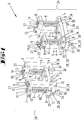
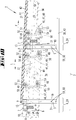
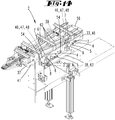
- a suspension set 1 according to the invention is first presented according to a first preferred embodiment.
- Whose in Fig. 1 Components shown can, like the Figures 2-7 show by way of example, integrate them into the structure of a vibration conveyor 2 according to the invention, so that they enable a so-called countermass to be suspended there (as will be described below).
- the suspension set 1 is thus a suspension set for a vibratory conveyor 2.
- it comprises four suspension units 4, each of which has a support 5, a spring 6, a first spring connection part 7 and a second spring connection part 8.
- each carrier 5 has a first carrier end section 9 adjoining its upper longitudinal end and a second carrier end section 10 adjoining its lower longitudinal end.
- Each spring 6 has a first spring end section 11 extending from its upper spring end and a second spring end section 12 extending from its lower longitudinal end.
- the respective first support end section 9 is coupled to the first spring end section 11 by means of the first spring connection part 7.
- a holding part 13 is fastened (eg screwed) to each first carrier end section 9 in a manner not shown in detail, which part extends transversely to a longitudinal direction L F of the spring 6.
- a through opening 14 is made in the first spring connection part 7, the hollow cross-section of which is not bordered on a side facing the holding part 13 and which is bordered in a semicircle on the side facing away from the holding part 13, the circular diameter of the semicircular border roughly corresponding to the outer diameter of the spring 6 .
- the dimension of the hollow cross-section in the direction transverse to the semicircle is somewhat smaller than the outer diameter of the spring 6.
- the first spring connection part 7 has through bores 15 oriented transversely to the longitudinal direction L F , through each of which a screw is inserted into an in Fig. 1 Threaded bore 21, not shown, is screwed into holding part 13. Since the cross section of the through opening 14 on the side facing the holding part 13 is flattened compared to the outer diameter of the spring 6, the first spring connection part 7 forms a tensioning plate for the spring 6. When the screws 17 (in Fig. 1 not shown, see but Fig. 5 ) are clamped, a first circumferential clamping bracket 16 for coupling the first spring end portion 11 is formed.
- a second circumferential clamping bracket 18 for coupling to the second spring end section 12 is formed on each suspension unit 4 by means of the second spring connection part 8.
- the second spring connection parts 8 structurally correspond to the first spring connection parts 7.
- Two through bores 20 extend transversely to the longitudinal direction L F of the spring 6 through every second coupling device 8.
- a support plate 19 is arranged between every two adjacent second spring connection parts 8.
- two threaded bores 22 each extend (see e.g. Fig. 6 ).
- a screw 23 is inserted through each through hole 20 (see also Fig. 6 ) and screwed into the associated threaded hole 22. If the screws 23 are tightened, the second circumferential clamping bracket 18 results Fig. 1 In the rest state shown, its spring 6 extends on each suspension unit 4 parallel to a longitudinal section 25 of the carrier 5, the springs 6 in the example being cylinder compression springs.
- the suspension set 1 has two suspension assemblies 24, of which each suspension assembly 24 has two suspension units 4, namely a first suspension unit 4 in the front in the direction of view of FIG Fig. 1 each so-called second suspension unit 4 located behind it.
- each suspension assembly 24 in the example, on each of the two suspension units 4 on the holding part 13 connected to the first support end section 9 there is a threaded through hole 26 (cf. Fig. 6 ), whereby a threaded adjustment element 27 is screwed through each threaded through hole 26, so that a respective geometrical longitudinal axis L E extends perpendicularly to a geometrical center plane passing between the two suspension units 4 of a suspension assembly 24 (in Fig. 1 not shown) extends.
- the carrier 5 has fastening means 28 at its second carrier end section 10, which are two parallel through-bores 29 running perpendicular to the longitudinal direction L F of the spring 6. These run transversely through a carrier segment 30 which also extends perpendicular to the longitudinal direction L F and is part of the second carrier end section 10.
- Each suspension assembly 34 has a connecting part 31 which is arranged between the two carrier segments 30 of a suspension assembly 24 under consideration. This arrangement is also in Fig. 5 shown. Accordingly, the two carrier segments 30, ie the two second carrier end sections 10, are connected to the connecting part 31 on opposite sides of the connecting part 31 within a suspension assembly 24. In the example chosen, the carrier segments 30 are screwed tightly to the connecting part 31 by means of screws 32.
- Fig. 1 shown embodiment of a suspension set 1 the total of four suspension units 4, insofar as they belong to the same suspension assembly 24, that is in pairs, only by means of a connection between their respective support end sections 10 and are connected to one another by means of a further connection between their respective second spring connection parts 8.
- the two suspension devices 4, which belong to a common suspension assembly 24 of the suspension set 1 are free of connection.
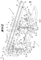
- Fig. 2 illustrated allow the described components of the suspension set 1 in their assembled state, ie as part of the vibration conveyor 2, a counterweight 33 to suspend oscillating, the respective carrier 5 each extending laterally outside (ie not inside as in the prior art) of the countermass.
- a gap 34 is formed between each carrier segment 30 and the second spring connection part 8 arranged above it (see also correspondingly in the sectional view of FIG Fig. 6 ).
- a respective support segment 30 has a threaded through-hole 35 directed transversely to the gap 34, through which a threaded adjusting element 36 (in the example a screw) is screwed so that a free end 65 of the adjusting element 36 into the gap 34 protrudes.
- the gap width of the gap 34 is 5 mm.
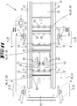
- this vibratory conveyor 2 contains all the components of the in Fig. 1 shown suspension sets 1 in the assembled state.
- This in Fig. 1 The suspension set 1 shown was used to build the in Figures 2 to 6
- the vibration conveyor 2 shown is used, so that the components of the suspension set 1 are now components of the vibration conveyor 2, which together form a suspension device 3.
- the vibratory conveyor 2 therefore, to avoid repetitions Reference is also made to the preceding description of these components.
- the vibratory conveyor 2 has a vibrator 37, a counterweight 33, a machine base 38, a vibration drive and the components of the in Fig. 1 shown suspension sets formed suspension device 3.
- the vibration conveyor 2 is designed as a linear vibration conveyor which extends along a longitudinal direction L;
- the conveying direction F also runs accordingly along the longitudinal direction L.
- the counterweight 33 comprises two cheeks 40 oriented in the longitudinal direction L, transversely spaced from one another and connected to one another connected longitudinal beams 41.
- a longitudinal profile 42 which is open at the top and which can be used to attach superstructures such as conveyor rails, conveyor and sorting lines or the like, extends on the upper side along the longitudinal direction L.
- the two longitudinal members 41 are located with overlapping areas between the cheeks 40 (cf. Fig. 5 ).
- the oscillator 37 is connected to the counter mass 33 by means of a first group of springs and is sprung relative to the counter mass 33 by means of the first group of springs, that is to say it is held movably.
- the oscillator 37 can be excited or driven to oscillate relative to the counterweight 33 by means of the vibration drive arranged between the two cheeks 40 and between the two longitudinal members 41.
- the vibration drive comprises a magnetic drive 39 with an electromagnet 63 fastened to the counterweight 33 and an armature 64 mounted on the oscillator 37, which is spaced apart from the electromagnet by a magnetic gap that changes during operation.
- the suspension device 3 in the example comprises four suspension units 4, each of which has a carrier 5, a spring 6, a first spring connection part 7 and a second spring connection part 8.
- the spring connection part 7 is arranged above the spring connection part 8.
- Each carrier 5 has a first carrier end section 9 and a second carrier end section 10, the carrier end section 9 extending from an upper longitudinal end of the carrier 5 and the second carrier end section 10 extending from a lower longitudinal end of the carrier 5.
- Each spring 6 has a first spring end section 11 which extends from an upper longitudinal end of the spring 6, and a second spring end section 12 which extends from a lower longitudinal end of the spring 6.
- the springs 6 of the four suspension units 4 form a second group of springs, by means of which the counterweight 33 is resiliently suspended from the suspension device 3.
- the first support end section 9 is coupled to the first spring end section 11 by means of the first spring connection part 7.
- the second support end section 10 is connected to the machine base 38, which in the example is a base plate 43.
- the carrier segments 30 are screwed to the connecting part 31 by means of the screws 32 (see FIG Fig.
- the connecting part 31 is connected to the base plate 43 in a manner not shown in the figures (for example also by means of screws).
- the second spring connection part 8 is connected to the counterweight 33, as will be described below.
- the second support end section 10 of each of the four supports 5 is arranged outside of the counterweight 33 and outside of the oscillator 37 with respect to respective reference planes which are oriented transversely to the longitudinal direction L of the vibration conveyor 2.
- the drawing plane, for example from Figure 5 corresponds to a reference plane which leads through the second carrier end section 10 shown on the left therein and which is oriented transversely to the longitudinal direction L of the vibratory conveyor 2.
- the drawing plane of Figure 5 also a reference plane which leads through the second carrier end section 10 shown on the right therein and which is oriented transversely to the longitudinal direction L of the vibratory conveyor 2.
- the respective reference plane under consideration is the same reference plane for the two second carrier end sections 10.
- a respective second support end section 10 is arranged in the respective reference plane leading through it and oriented transversely to the longitudinal direction L outside the oscillator 37 and outside the counterweight 33.
- second carrier end sections 10 arranged on the right select a respective reference plane which leads through the respectively considered second carrier end section 10 and which is oriented transversely to the longitudinal direction L.
- the respective reference planes of these two second support end sections 10 can also be selected to be the same due to their mutually opposite position. It is clear from the foregoing that the reference planes are imaginary planes for observation, so that instead of reference planes, one can also speak of observation planes or of reference or observation cross-sections.
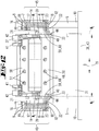
- Fig. 6 it is indicated that the respective outer sides 44 of the cheeks 40 each span a cheek plane W E which extends beyond the contour of the respective cheek 40. It is provided here that each of the two second support end sections 10 is arranged laterally outside the intermediate space bordered by the two cheek planes W E.
- a respective carrier 5 extends in a carrier longitudinal section 45, which extends along the entire length of the spring 6 adjacent to it, in a reference plane oriented transversely to the longitudinal direction L of the vibratory conveyor 2 (see, for example, the drawing plane of FIG Fig. 6 ) continuously to the side outside of the space bordered by the two cheek planes W E and to that extent to the side of the oscillator 37 and also to the side of the counterweight 33.
- the suspension device 3 comprises two suspension assemblies 24 which are arranged at a distance from one another in the longitudinal direction L of the vibratory conveyor 2.
- Each suspension assembly 24 has one viewed in the direction of FIG Fig. 2 so-called first suspension unit 4 lying in front and one in the direction of view from Fig. 2 so-called second suspension unit 4 lying obliquely behind it.
- An adjusting element 27, in the example a screw is screwed through each threaded through hole 26.
- the longitudinal ends of two adjustment elements 27, which belong to the same suspension assembly 24, point from opposite directions to the oscillator 37. By rotating the two adjustment elements 27, a respective lateral free space to the oscillator 37 can be changed, thereby limiting the lateral oscillation.
- each suspension assembly 24 has a connector 31.
- the second beam end portion 10 of the beam 5 of the first suspension unit 4 is connected to the connecting part 31 on a first side of the connecting part 31, and the second beam end portion 10 of the beam 5 of the second suspension unit 4 is connected to the connecting part 31 on the opposite side Side of the connecting part 31 connected.
- the second carrier end section 10 has a carrier segment 30 running transversely to the geometric longitudinal axis L F , so that the carrier 5 has an essentially L-shaped profile.
- a respective carrier segment 30 is spaced apart from the second spring connection part 8 adjacent to it by a gap 34.
- a threaded through hole 35 into which an adjusting element 36 extends through the carrier segment 30 in a direction parallel to the longitudinal axis L F of the spring 6, that is, transversely to the gap 34 is screwed so that a free end of the adjusting element 36 extends into the gap 34.
- the total of four adjusting elements 36 can be used for fine adjustment of the suspension device 3, more precisely the gap width of the respective column 34.
- the gap width of the gap 34 is preferably 5 mm in each case.
- each suspension assembly 24 has a support plate 19.
- the spring 6 of the first suspension unit 4 is connected at its second spring end portion 12 by means of the second spring connection part 8 of the first suspension unit 4 to the support plate 19 on a first side of the support plate 19, and the spring 6 of the second suspension unit 4 is on its second spring end section 12 connected to the support plate 19 by means of the second spring connection part of the second suspension unit 4 on a side of the support plate 19 opposite to the first side.
- the counterweight 8 is supported on a respective support plate 19.
- the cheeks 40 are fastened to the support plates 19 by means of screws not shown in the figures.
- the oscillator 37 is connected to the counterweight 33 by means of springs 46 of a first group of springs and is thereby held so that it can oscillate relative to it.
- springs 46 of a first group of springs and is thereby held so that it can oscillate relative to it.
- there are two springs 46 are present, each of which is a leaf spring package 48 which is composed of several leaf springs 47.
- the carrier 5 and the springs 6 of the second group of springs are arranged laterally outside of the cheek planes W E
- the springs 46 extend inside the vibration conveyor 2 between the cheeks 40 of the counterweight 33 and between the longitudinal members 41 of the oscillator 37, see also FIG Figures 5 and 6th .
- the in Fig. 4 Installation position shown upper ends of the leaf springs 47 are between a to the plane of the drawing Fig.
- the upper spacer 49 is accommodated between the longitudinal beams 41 so as to be rotatable about its longitudinal axis and can be secured in a desired rotational position by means of locking screws 52 engaging therein through bores in the longitudinal beams 41.
- the lower spacer 49 can be displaced along arched grooves 53 inserted into the cheeks 40 and penetrating them with further locking screws 54 engaging through them and can be releasably fixed in a desired position. In this way, the in Fig.
- a preferred conveying direction F is in Fig. 4 indicated by a directional arrow.
- Fig. 7 shows a perspective view of a second preferred exemplary embodiment of a suspension set 1 according to the invention.
- This also comprises four suspension units 4, each individual suspension unit 4 again having a carrier 5, a spring 6, a first spring connection part 7 and a second spring connection part 8.
- Fig. 7 shows that the suspension units 4 can be connected to one another in pairs by means of a connecting part 31 each on the respective second carrier end sections 10.
- 29 screws in Fig. 7 not shown
- inserted into matching threaded holes in Fig. 7 not shown
- Fig. 7 shows an arrangement in which the two connecting parts 31 extend parallel to one another and at a distance from one another.
- connection the two connecting parts 31 to one another by means of a longitudinal connecting part 57; screws (in Fig. 7 not shown) inserted through through openings 58 in the relevant connecting part and inserted into matching threaded bores (in Fig. 7 not shown) of the longitudinal connecting part 57 are screwed.
- the connecting parts 31 and the longitudinal connecting part 57 do not necessarily belong to the suspension set 1. If these components are not present, the four suspension units 4 are completely separated from one another. If, on the other hand, the two connecting parts 31 and the longitudinal connecting part 57 are present and fastened as described above, the four suspension units 4 are connected to one another in pairs by means of a connecting part 31 each at their respective second support end sections 10.
- a fastening device 59 belongs to each suspension unit 4.
- This comprises a connection part 60 and can in particular screws for connection to a second spring connection part 8 and / or for connection to a counter mass 33 of a vibration conveyor 2 (see FIG Figures 8-12 ) exhibit.
- the connecting part 60 Threaded holes (in Fig. 7 not shown) in which screws (in Fig. 7 not shown), which are inserted through the through bores 29, can be screwed in, and the connecting part 60 can have through bores which, when mounted on a countermass 33 of a vibration conveyor, are used to insert fastening screws (in Fig. 7 not shown).
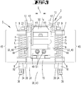
- the Figures 8-12 show a vibratory conveyor 2 according to the invention according to a second preferred embodiment.
- This comprises a suspension device 3, which, now assembled with further components of the vibration conveyor 2, components of the in Fig. 7 Has suspension sets 1 shown.
- two suspension units 4 connected by a connecting part 31 each form a suspension assembly 24.
- the respective connecting parts 60 are screwed onto the cheeks 40 of the countermass 33 from the outside laterally by means of screws.
- the counterweight 33 is thereby suspended from the total of four suspension units 4 of the suspension device 3 such that it can vibrate.
- the vibration drive comprises two magnetic drives 39, which in principle each have the structure described for the first example. However, magnetic drives 39 are attached next to one another.
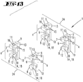
- Fig. 13 shows a suspension set 1 according to the invention according to a third preferred embodiment.
- This in turn comprises four suspension units 4, each of which has a carrier 5, a spring 6, a first spring connection part 7 and a second spring connection part 8.
- the four suspension units 4 are completely separated from one another in the non-assembled state shown.
- Fig. 14 shows a vibratory conveyor 2 according to the invention according to a third preferred embodiment.
- Its suspension device 3 contains, now in the assembled state, the components of the in Fig. 13 1.
- Each beam 5 is attached to its second beam end portion 10 by means of a suspension set shown in FIG Fig. 14 Screw connection, not shown, is attached to a machine base 38 which is like a frame in the example.
- a so-called accumulation section designated overall by 61 is screwed.
- This has several conveyor tracks 62 along which parts of the goods to be conveyed (in Fig. 14 not shown) can be promoted and in particular sorted or the like.
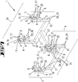
- Fig. 15 shows a vibratory conveyor 2 according to the invention according to a fourth preferred embodiment.
- This is designed as a round vibratory conveyor.
- An oscillator 37 is supported here by means of three leaf spring assemblies 48 that are equally spaced apart from one another in the circumferential direction, so as to be able to oscillate on a likewise round counterweight 33.
- the vibratory conveyor 2 has a vibratory drive, which in this example comprises three magnetic drives 39; These, too, are evenly spaced from one another in a circumferential direction U along a circumference of the vibration conveyor 2.
- the circumferential direction U of the vibratory conveyor 2 runs along its circumference, which leads around an imaginary geometric central axis of the vibratory conveyor.
- Each magnetic drive 39 has an electromagnet 63 fastened to the counterweight 33 and an armature 64 fastened to the oscillator 37, which is spaced apart from the electromagnet 63 by a magnet gap that changes continuously during operation.
- the oscillator 37 can be excited to oscillate or vibrate relative to the counterweight 33.
- Superstructures for example for conveying, sorting (or the like) of conveyed goods or small parts, can be mounted on the upper side of the oscillator 37.
- the vibration conveyor 2 has a suspension device 3 which, in the example, comprises three suspension units 4, each of which in turn has a carrier 5, a spring 6 and a first spring connection part 7 and a second spring connection part 8.
- the Suspension units 4 are evenly spaced from one another along the circumference.
- Each support 5 extends vertically, is coupled to the spring 6 at its upper, first support end section 9 by means of the first spring connection part 7, and is screwed onto a machine base 38 at its lower, second support end section 10.
- the spring 6 is connected to the counterweight 33 by means of the second spring connection part 8.
- the counterweight 33 is suspended so that it can vibrate by means of the three suspension units 4.
- Fig. 15 shows the assembled state, even if the fastening screws are not shown in detail.
- Fig. 15 shows an example of three dashed reference planes which are oriented transversely to the circumferential direction U and each of which leads through one of the second carrier sections 10.
- every second support end section 10 is arranged outside of the oscillator 37 and outside of the counterweight 33.
- the three suspension units 4 are equally spaced from one another on the circumference in pairs. Your in Figure 15 indicated respective reference planes run in different directions.
- the described components of the suspension device 3 can, regardless of their assembly, also be components of a suspension set 1 according to the invention according to a fourth preferred embodiment.
- the invention also relates to design forms in which some of the features mentioned in the above description are not implemented, in particular if they are recognizable for the respective purpose or can be replaced by other technically equivalent means.
- ⁇ b> ⁇ u> List of reference symbols ⁇ /u> ⁇ /b> 1 Suspension set 27 Adjustment element 2 Vibratory conveyor 28 Fasteners 3 Suspension device 29 Through hole 4th Suspension unit 30th Carrier segment 5 carrier 31 Connecting part 6th feather 32 screw 7th first spring connection part 33 Counter mass 8th second spring connection part 34 gap 9 first beam end section 35 Thread through hole 10 second beam end section 36 Adjustment element 11 first spring end section 37 Schwinger 12 second spring end section 38 Machine base 13 Holding part 39 Magnetic drive 14th Through opening 40 Cheeks 15th Through holes 41 Side member 16 first circumferential clamp bracket 42 Longitudinal profile 43 Base plate 17th screw 44 Outside 18th second circumferential clamp bracket 45 Beam length section 46 feather 19th Support plate 47 Leaf springs 20th Through hole 48 Leaf spring package 21st Threaded hole 49 Spacer
Abstract
Die Erfindung betrifft gemäß einem ersten Aspekt ein Aufhängungsset, insbesondere für einen Vibrationsförderer (2), wobei das Aufhängungsset (1) mehrere Aufhängungseinheiten (4) umfasst, von denen jede Aufhängungseinheit (4) einen Träger (5), eine Feder (6) sowie ein erstes Federanschlussteil (7) und ein zweites Federanschlussteil (8) aufweist, wobei der Träger (5) einen ersten Trägerendabschnitt (9) und einen zweiten Trägerendabschnitt (10) aufweist, wobei die Feder (6) einen ersten Federendabschnitt (11) und einen zweiten Federendabschnitt (12) aufweist und wobei der erste Trägerendabschnitt (9) mittels des ersten Federanschlussteils (7) mit dem ersten Federendabschnitt (11) gekoppelt ist, wobei entweder die Aufhängungseinheiten (4) voneinander getrennt sind oder die Aufhängungseinheiten (4) paarweise nur mittels einer direkten oder indirekten Verbindung ihrer jeweiligen zweiten Trägerendabschnitte (10) miteinander verbunden sind oder die Aufhängungseinheiten (4) paarweise nur mittels einer direkten oder indirekten Verbindung ihrer jeweiligen zweiten Federanschlussteile (8) miteinander verbunden sind oder die Aufhängungseinheiten (4) paarweise nur mittels einer direkten oder indirekten Verbindung ihrer jeweiligen zweiten Trägerendabschnitte (10) und mittels einer direkten oder indirekten Verbindung ihrer jeweiligen zweiten Federanschlussteile (8) miteinander verbunden sind. Gemäß einem zweiten Aspekt betrifft die Erfindung einen Vibrationsförderer. Zur vorteilhaften Ausgestaltung weist dieser die Bestandteile eines erfindungsgemäßen Aufhängungssets auf, wobei ein jeweiliger zweiter Trägerendabschnitt (10) in einer durch ihn führenden Bezugsebene, die quer zu einer Längsrichtung (L) oder einer Umfangsrichtung (U) des Vibrationsförderers (2) orientiert ist, außerhalb des Schwingers (37) und insbesondere außerhalb der Gegenmasse (33) angeordnet ist.According to a first aspect, the invention relates to a suspension set, in particular for a vibration conveyor (2), the suspension set (1) comprising a plurality of suspension units (4), of which each suspension unit (4) has a support (5), a spring (6) and having a first spring connection part (7) and a second spring connection part (8), the carrier (5) having a first carrier end section (9) and a second carrier end section (10), the spring (6) having a first spring end section (11) and a having a second spring end section (12) and wherein the first support end section (9) is coupled to the first spring end section (11) by means of the first spring connection part (7), either the suspension units (4) being separated from one another or the suspension units (4) in pairs only by means of a direct or indirect connection of their respective second support end sections (10) are connected to one another or the suspension units (4) in pairs only medium s a direct or indirect connection of their respective second spring connection parts (8) are connected to one another or the suspension units (4) in pairs only by means of a direct or indirect connection of their respective second support end sections (10) and by means of a direct or indirect connection of their respective second spring connection parts (8 ) are connected to each other. According to a second aspect, the invention relates to a vibratory conveyor. For an advantageous embodiment, this has the components of a suspension set according to the invention, with a respective second support end section (10) in a reference plane leading through it, which is oriented transversely to a longitudinal direction (L) or a circumferential direction (U) of the vibration conveyor (2), outside of the oscillator (37) and in particular outside of the counter mass (33).
Description
Die Erfindung betrifft gemäß einem ersten Aspekt ein Aufhängungsset, vorzugsweise für einen Vibrationsförderer.According to a first aspect, the invention relates to a suspension set, preferably for a vibration conveyor.
Gemäß einem zweiten Aspekt betrifft die Erfindung einen Vibrationsförderer, aufweisend einen Schwinger, eine Gegenmasse, eine Maschinenbasis, eine Aufhängungseinrichtung und einen Vibrationsantrieb, wobei der Schwinger mittels einer ersten Federgruppe mit der Gegenmasse verbunden und relativ zu der Gegenmasse beweglich gehalten ist, wobei der Schwinger mittels des Vibrationsantriebs antreibbar ist, wobei die Gegenmasse mittels der Aufhängungseinrichtung mit der Maschinenbasis verbunden und relativ zu der Maschinenbasis beweglich gehalten ist, wobei die Aufhängungseinrichtung mehrere Aufhängungseinheiten umfasst, von denen jede Aufhängungseinheit einen Träger, eine Feder, ein erstes Federanschlussteil und ein zweites Federanschlussteil aufweist, wobei deren Träger einen ersten Trägerendabschnitt und einen zweiten Trägerendabschnitt aufweist, wobei deren Feder einen ersten Federendabschnitt und einen zweiten Federendabschnitt aufweist, wobei die Federn der Aufhängungseinheiten eine zweite Federgruppe bilden, wobei an einer jeweiligen Aufhängungseinheit der erste Trägerendabschnitt mittels des ersten Federanschlussteils mit dem ersten Federendabschnitt gekoppelt ist, der zweite Trägerendabschnitt mit der Maschinenbasis verbunden ist und das zweite Federanschlussteil mit der Gegenmasse verbunden ist.According to a second aspect, the invention relates to a vibration conveyor having a vibrator, a counter mass, a machine base, a suspension device and a vibration drive, the vibrator being connected to the counter mass by means of a first group of springs and being held movably relative to the counter mass, the vibrator being held by means of of the vibration drive is drivable, wherein the counterweight is connected to the machine base by means of the suspension device and is held movably relative to the machine base, wherein the suspension device comprises a plurality of suspension units, of which each suspension unit has a carrier, a spring, a first spring connection part and a second spring connection part, the support of which has a first support end section and a second support end section, the spring of which has a first spring end section and a second spring end section, the springs of the suspension units having a second e form a spring group, the first support end section being coupled to the first spring end section by means of the first spring connection part, the second support end section being connected to the machine base and the second spring connection part being connected to the counterweight on a respective suspension unit.
Aus
Vor obigem Hintergrund liegt einem Aspekt der Erfindung die Aufgabe zugrunde, eine Möglichkeit zu schaffen, Vibrationsförderer, insbesondere auf Puffern abgestützte Vibrationsförderer, vorteilhaft, insbesondere nachträglich, so weiterzubilden, dass die zuvor beschriebenen Nachteile und Einschränkungen zumindest teilweise, insbesondere vollständig, vermieden werden können. Vor obigem Hintergrund liegt einem weiteren Aspekt der Erfindung die Aufgabe zugrunde, einen Vibrationsförderer anzugeben, der gegenüber den bekannten Vibrationsförderern vorteilhaft weitergebildet ist. Insbesondere wird dadurch angestrebt, dass dadurch die beschriebenen Einschränkungen und Nachteile zumindest teilweise, insbesondere vollständig, vermieden werden können.Against the above background, one aspect of the invention is based on the object of creating a possibility of developing vibration conveyors, in particular vibration conveyors supported on buffers, advantageously, in particular subsequently, in such a way that the disadvantages and restrictions described above can be at least partially, in particular completely, avoided. Against the above background, a further aspect of the invention is based on the object of specifying a vibration conveyor which is advantageously developed in relation to the known vibration conveyors. In particular, the aim is to ensure that the restrictions and Disadvantages can at least partially, in particular completely, be avoided.
Gemäß ihrem ersten Aspekt schlägt die Erfindung zur Lösung der Aufgabe ein Aufhängungsset vor, das mehrere Aufhängungseinheiten umfasst, von denen jede Aufhängungseinheit einen Träger, eine Feder sowie ein erstes Federanschlussteil und ein zweites Federanschlussteil aufweist, wobei der Träger einen ersten Trägerendabschnitt und einen zweiten Trägerendabschnitt aufweist, wobei die Feder einen ersten Federendabschnitt und einen zweiten Federendabschnitt aufweist und wobei der erste Trägerendabschnitt mittels des ersten Federanschlussteils mit dem ersten Federendabschnitt gekoppelt ist, wobei entweder die Aufhängungseinheiten voneinander getrennt sind oder die Aufhängungseinheiten paarweise nur mittels einer direkten oder indirekten Verbindung ihrer jeweiligen zweiten Trägerendabschnitte miteinander verbunden sind oder die Aufhängungseinheiten paarweise nur mittels einer direkten oder indirekten Verbindung ihrer jeweiligen zweiten Federanschlussteile miteinander verbunden sind oder die Aufhängungseinheiten paarweise nur mittels einer direkten oder indirekten Verbindung ihrer jeweiligen zweiten Trägerendabschnitte miteinander und mittels einer direkten oder indirekten Verbindung ihrer jeweiligen zweiten Federanschlussteile miteinander verbunden sind.According to its first aspect, the invention proposes a suspension set to achieve the object, which comprises a plurality of suspension units, each suspension unit having a carrier, a spring and a first spring connection part and a second spring connection part, the carrier having a first carrier end section and a second carrier end section , wherein the spring has a first spring end section and a second spring end section and wherein the first support end section is coupled to the first spring end section by means of the first spring connection part, either the suspension units being separated from one another or the suspension units in pairs only by means of a direct or indirect connection of their respective second support end sections are connected to one another or the suspension units are connected to one another in pairs only by means of a direct or indirect connection of their respective second spring connection parts or the Au Suspension units are connected in pairs only by means of a direct or indirect connection of their respective second support end sections to one another and by means of a direct or indirect connection of their respective second spring connection parts.
Ein erfindungsgemäßes Aufhängungsset ermöglicht im Vergleich zu dem aus
Darüber hinaus eignet sich ein erfindungsgemäßes Aufhängungsset nicht nur zum Gebrauch bei der erstmaligen Montage eines Vibrationsförderers, sondern die Erfindung eröffnet zusätzlich auch die Möglichkeit, dass ein erfindungsgemäßes Aufhängungsset zum nachträglichen Umbau bzw. zu einer Nachrüstung an einem vorhandenen, zum Beispiel aus
Nachfolgend werden exemplarisch bevorzugte Möglichkeiten zur zweckmäßigen und vorteilhaften Weiterbildung vorgestellt:Preferred options for expedient and advantageous further development are presented below as examples:
Bevorzugt ist, dass an jeder Aufhängungseinheit der Träger an dem zweiten Trägerendabschnitt ein Befestigungsmittel aufweist oder mit einem Befestigungsmittel verbunden ist, insbesondere zur Befestigung an einer Maschinenbasis eines Vibrationsförderers. Bei dem Befestigungsmittel kann es sich zum Beispiel um eine Durchsteckbohrung oder um eine Gewindebohrung für eine Schraubverbindung handeln.It is preferred that on each suspension unit the carrier has a fastening means on the second carrier end section or is connected to a fastening means, in particular for fastening to a machine base of a vibration conveyor. The fastening means can be, for example, a through hole or a threaded hole for a screw connection.
Zur vorteilhaften Ausgestaltung ist auch bevorzugt, dass sich betreffend eine jeweilige Aufhängungseinheit ihre Feder entlang, insbesondere parallel zu, einem Längsabschnitt ihres Trägers erstreckt und/oder dass es sich bei den Federn um Zylinderfedern, insbesondere um Zylinderdruckfedern, handelt. Insbesondere bei Verwendung solcher Federn kann im Vergleich zu Pufferfüßen die Schwingungsübertragung in das Fundament bzw. in ein Maschinengestell deutlich verringert werden, so dass im Betrieb höhere Schwingungs- bzw. Vibrations-Amplituden möglich sind. Vorzugsweise werden Federn gewählt, deren Materialbeschaffenheit bei Vibration zu keiner signifikanten mechanischen und maßlichen Veränderung führt, so dass insofern keine nachteiligen Auswirkungen an Übergängen zu benachbarten Baugruppen bestehen.For an advantageous embodiment, it is also preferred that, with regard to a respective suspension unit, its spring extends along, in particular parallel to, a longitudinal section of its carrier and / or that the springs are cylinder springs, in particular cylinder compression springs. In particular, when using such springs, the vibration transmission into the foundation or into a machine frame can be significantly reduced compared to buffer feet, so that higher vibration or vibration amplitudes are possible during operation. Springs are preferably selected whose material properties do not lead to any significant mechanical or dimensional change when they vibrate, so that there are no adverse effects at transitions to adjacent assemblies.
Es besteht die Möglichkeit, dass an jeder Aufhängungseinheit mittels des ersten Federanschlussteils eine erste Umfangs-Klemmhalterung gebildet ist, in welcher der erste Federendabschnitt eingespannt ist, und insbesondere dass mittels des zweiten Federanschlussteils eine zweite Umfangs-Klemmhalterung gebildet ist, in welcher der zweite Federendabschnitt eingespannt ist. Die Federanschlussteile können z.B. als Spannteile, vorzugsweise als Spannplatten, ausgebildet sein. Vorzugsweise kann das Spannteil eine Durchgangsöffnung aufweisen, deren Hohlquerschnitt auf einer Seite unberandet ist und dieser Seite gegenüberliegend halbkreisförmig berandet ist, wobei der zu der Halbkreisform korrespondierende Durchmesser dem Durchmesser der Zylinderfeder entspricht oder im Vergleich dazu um einige hundertstel oder zehntel Millimeter größer ist.There is the possibility that a first circumferential clamping bracket, in which the first spring end section is clamped, is formed on each suspension unit by means of the first spring connection part, and in particular that a second circumferential clamping bracket is formed by means of the second spring connection part, in which the second spring end section is clamped. The spring connection parts can, for example, be designed as clamping parts, preferably as clamping plates. The clamping part can preferably have a through-opening, the hollow cross-section of which is not bordered on one side and has a semicircular border on the opposite side, the diameter corresponding to the semicircular shape corresponding to the diameter of the cylinder spring or being a few hundredths or tenths of a millimeter larger by comparison.
Als zweckmäßig wird angesehen, dass das Aufhängungsset eine Aufhängungsbaugruppe oder zwei oder mehr Aufhängungsbaugruppen umfasst, wobei jede Aufhängungsbaugruppe eine erste Aufhängungseinheit und eine zweite Aufhängungseinheit aufweist. Die hier genannten ersten und zweiten Aufhängungseinheiten zählen zu den eingangs genannten Aufhängungseinheiten. Bevorzugt ist, dass an der ersten Aufhängungseinheit und an der zweiten Aufhängungseinheit an einem mit dem jeweiligen ersten Trägerendabschnitt verbundenen Halteteil oder an dem jeweiligen ersten Trägerendabschnitt eine Gewindedurchgangsbohrung ausgebildet ist und dass durch jede dieser Gewindedurchgangsbohrungen je ein mit Gewinde versehenes Einstellelement, insbesondere ein Schraube, hindurchgeschraubt ist, wobei sich eine jeweilige geometrische Längsachse der Einstellelemente senkrecht zu einer mittig zwischen der ersten Aufhängungseinheit und der zweiten Aufhängungseinheit hindurchführenden geometrischen Mittelebene erstreckt. Die Einstellelemente ermöglichen es vorteilhaft, dass eine lichte Weite zwischen den beiden Aufhängungseinheiten stufenlos eingestellt, also wahlweise verkleinert oder vergrößert werden kann. Wenn das Aufhängungsset an einem Vibrationsförderer montiert ist, bildet es mit seinen Bestandteilen eine Aufhängungseinrichtung des Vibrationsförderers, wobei an jeder Aufhängungseinheit des Aufhängungssets bzw. der Aufhängungseinrichtung ein seitlicher Abstand zwischen dem Halteteil oder dem ersten Trägerendabschnitt zu dem Schwinger oder zu der Gegenmasse des Vibrationsförderers eingestellt werden kann, um Schwingungsamplituden des Vibrationsförderers in seiner zu der Förderrichtung quer orientierten Seitenrichtung zu begrenzen. Bevorzugt ist, dass die beiden genannten geometrischen Längsachsen der Einstellelemente miteinander fluchten.It is considered expedient that the suspension set comprises one suspension assembly or two or more suspension assemblies, each suspension assembly having a first suspension unit and a second suspension unit. The first and second suspension units mentioned here are among the suspension units mentioned at the beginning. It is preferred that a threaded through hole is formed on the first suspension unit and on the second suspension unit on a holding part connected to the respective first carrier end section or on the respective first carrier end section and that a threaded adjustment element, in particular a screw, is screwed through each of these threaded through holes is, wherein a respective geometric longitudinal axis of the adjusting elements extends perpendicular to a central geometric plane passing through between the first suspension unit and the second suspension unit. The adjustment elements advantageously make it possible for a clear width between the two suspension units to be continuously adjusted, that is to say can be optionally reduced or increased. When the suspension set is mounted on a vibratory conveyor, it forms with its components a suspension device for the vibratory conveyor, with a lateral spacing on each suspension unit of the suspension set or the suspension device can be adjusted between the holding part or the first support end section to the oscillator or to the counterweight of the vibration conveyor in order to limit vibration amplitudes of the vibration conveyor in its lateral direction oriented transversely to the conveying direction. It is preferred that the two mentioned geometric longitudinal axes of the adjustment elements are aligned with one another.
Bei einem bevorzugten Ausführungsbeispiel ist vorgesehen, dass jede Aufhängungsbaugruppe ein Verbindungsteil aufweist, wobei betreffend eine jeweilige Aufhängungsbaugruppe der zweite Trägerendabschnitt des Trägers der ersten Aufhängungseinheit mit dem Verbindungsteil an einer ersten Seite des Verbindungsteils verbunden ist und der zweite Trägerendabschnitt des Trägers der zweiten Aufhängungseinheit mit dem Verbindungsteil an einer der ersten Seite entgegengesetzten, zweiten Seite des Verbindungsteils verbunden ist. Vorzugsweise weist ein jeweiliges Verbindungsteil Befestigungsmittel, insbesondere zur Befestigung des Verbindungsteils an einer Maschinenbasis eines Vibrationsförderers, auf. Bei den Befestigungsmitteln kann es sich zum Beispiel um, insbesondere mit Gewinde versehene, Durchgangsbohrungen handeln.In a preferred embodiment it is provided that each suspension assembly has a connection part, with the second support end section of the support of the first suspension unit being connected to the connection part on a first side of the connection part and the second support end section of the support of the second suspension unit being connected to the connection part with regard to a respective suspension assembly is connected to a second side of the connecting part opposite the first side. A respective connection part preferably has fastening means, in particular for fastening the connection part to a machine base of a vibration conveyor. The fastening means can, for example, be through bores, in particular threaded holes.
Des Weiteren besteht die Möglichkeit, dass betreffend jede Aufhängungseinheit der zweite Trägerendabschnitt des Trägers ein zu der geometrischen Längsachse der Feder quer verlaufendes Trägersegment aufweist, dass zwischen dem Trägersegment und dem zweiten Federanschlussteil ein Spalt gebildet ist und dass sich durch das Trägersegment eine quer zu dem Spalt gerichtete Gewindedurchgangsbohrung erstreckt, durch die ein mit Gewinde versehenes Justierelement, insbesondere eine Schraube, hindurchgeschraubt ist, so dass ein freies Ende des Justierelements in den Spalt hineinragt. Bevorzugt ist, dass eine Spaltweite des Spalts in einer zu der geometrischen Längsachse der Feder parallelen Richtung weniger als 10 mm, insbesondere 5 mm oder etwa 5 mm beträgt, wobei der Begriff etwa vorzugsweise Abweichungen von bis zu 1 mm einschließt.Furthermore, there is the possibility that, with regard to each suspension unit, the second carrier end section of the carrier has a carrier segment running transversely to the geometrical longitudinal axis of the spring, that a gap is formed between the carrier segment and the second spring connection part and that a gap extends through the carrier segment directed threaded through hole extends through which a threaded adjusting element, in particular a screw, is screwed, so that a free end of the adjusting element protrudes into the gap. It is preferred that a gap width of the gap in a direction parallel to the geometric longitudinal axis of the spring is less than 10 mm, in particular 5 mm or approximately Is 5 mm, the term preferably including deviations of up to 1 mm.
Zur weiteren Ausgestaltung ist bevorzugt, dass jede Aufhängungsbaugruppe eine Stützplatte umfasst und dass betreffend eine jeweilige Aufhängungsbaugruppe die Feder der ersten Aufhängungseinheit an ihrem zweiten Federendabschnitt mittels des zweiten Federanschlussteils der ersten Aufhängungseinheit an die Stützplatte an einer ersten Seite der Stützplatte angeschlossen ist und die Feder der zweiten Aufhängungseinheit an ihrem zweiten Federendabschnitt mittels des zweiten Federanschlussteils der zweiten Aufhängungseinheit an die Stützplatte an einer zu der ersten Seite entgegengesetzten, zweiten Seite der Stützplatte angeschlossen ist, wobei insbesondere vorgesehen ist, dass in einer zu den geometrischen Längsachsen der Federn parallelen Richtung ein Abstand zwischen dem Verbindungsteil und der Stützplatte weniger als 10 mm, insbesondere 5 mm oder etwa 5 mm beträgt. Auch in diesem Zusammenhang schließt der Begriff "etwa" vorzugsweise Abweichungen von bis zu 1 mm ein.For a further refinement, it is preferred that each suspension assembly comprises a support plate and that, with regard to a respective suspension assembly, the spring of the first suspension unit is connected to its second spring end section by means of the second spring connection part of the first suspension unit to the support plate on a first side of the support plate and the spring of the second The suspension unit is connected to its second spring end section by means of the second spring connection part of the second suspension unit to the support plate on a second side of the support plate opposite to the first side, with provision being made in particular that a distance between the support plate in a direction parallel to the geometric longitudinal axes of the springs Connecting part and the support plate is less than 10 mm, in particular 5 mm or about 5 mm. In this context, too, the term “approximately” preferably includes deviations of up to 1 mm.
Alternativ ist bevorzugt, dass das Aufhängungsset Befestigungseinrichtungen umfasst, und dass an jeder Aufhängungseinheit die Feder an ihrem zweiten Federendabschnitt mittels des zweiten Federanschlussteils eine Befestigungseinrichtung angeschlossen oder anschließbar ist.Alternatively, it is preferred that the suspension set comprises fastening devices, and that a fastening device is or can be connected to each suspension unit at its second spring end section by means of the second spring connection part.
Ein erfindungsgemäßes Aufhängungsset kann zum Gebrauch bei Linear-Vibrationsförderern und/oder zum Gebrauch bei Rund-Vibrationsförderern angepasst sein.A suspension set according to the invention can be adapted for use with linear vibratory conveyors and / or for use with circular vibratory conveyors.
Betreffend ein Aufhängungsset für einen Rundförderer ist bevorzugt, dass das Aufhängungsset eine ungerade Mehrzahl an baugleichen Aufhängungseinrichtungen, insbesondere genau drei zueinander baugleiche Aufhängungseinrichtungen aufweist.With regard to a suspension set for a circular conveyor, it is preferred that the suspension set have an uneven number of identical suspension devices, in particular has exactly three suspension devices of identical construction.
Gemäß ihrem weiteren, einen Vibrationsförderer betreffenden Aspekt schlägt die Erfindung zur vorteilhaften Weiterbildung vor, dass der Vibrationsförderer als Linear-Vibrationsförderer ausgebildet ist, wobei ein jeweiliger zweiter Trägerendabschnitt in einer durch ihn führenden Bezugsebene, die zu einer Längsrichtung des Vibrationsförderers quer orientiert ist, außerhalb des Schwingers und insbesondere außerhalb der Gegenmasse angeordnet ist, oder dass der Vibrationsförderer als Rund-Vibrationsförderer ausgebildet ist, wobei ein jeweiliger Trägerendabschnitt in einer durch ihn führenden Bezugsebene, die zu einer Umfangsrichtung des Rund-Vibrationsförderers quer orientiert ist, außerhalb des Schwingers und insbesondere außerhalb der Gegenmasse angeordnet ist. Die genannten Bezugsebenen dienen zur Betrachtung der Anordnung der zweiten Trägerendabschnitte. Ein erfindungsgemäßer Vibrationsförderer weist vorzugsweise Bestandteile eines erfindungsgemäßen Aufhängungssets auf. Dabei sind die Bestandteile des Aufhängungssets in den Vibrationsförderer eingebaut und bilden so Bestandteile einer Aufhängungseinrichtung des Vibrationsförderers. Daher werden die Bestandteile eines erfindungsgemäßen Aufhängungssets und die Bestandteile einer erfindungsgemäßen Aufhängungseinrichtung mit den gleichen Begriffen beschrieben und in den Figuren auch mit gleichen Bezugszeichen gezeigt.According to its further aspect relating to a vibration conveyor, the invention proposes for an advantageous development that the vibration conveyor is designed as a linear vibration conveyor, with a respective second carrier end section in a reference plane leading through it, which is oriented transversely to a longitudinal direction of the vibration conveyor, outside the Oscillator and in particular is arranged outside the counterweight, or that the vibration conveyor is designed as a round vibration conveyor, with a respective support end section in a reference plane leading through it, which is oriented transversely to a circumferential direction of the round vibration conveyor, outside the vibrator and in particular outside the Counter mass is arranged. The mentioned reference planes serve to consider the arrangement of the second carrier end sections. A vibration conveyor according to the invention preferably has components of a suspension set according to the invention. The components of the suspension set are built into the vibratory conveyor and thus form components of a suspension device for the vibratory conveyor. The components of a suspension set according to the invention and the components of a suspension device according to the invention are therefore described using the same terms and are also shown in the figures with the same reference symbols.
Bei einer Ausgestaltung des Vibrationsförderers als Linear-Vibrationsförderer umfasst die Aufhängungseinrichtung vorzugsweise vier Aufhängungseinheiten, während bei einer Ausgestaltung des Vibrationsförderers als Rund-Vibrationsförderer bevorzugt ist, dass die Aufhängungseinrichtung drei Aufhängungseinheiten aufweist. Ein jeweiliger Träger ist mittels seines zweiten Trägerendabschnittes an der Maschinenbasis befestigt. Jeder Träger erstreckt sich ausgehend von seinem zweiten Trägerendabschnitt zu dem ersten Trägerendabschnitt nach oben, vorzugsweise senkrecht nach oben. Insofern kann der erste Trägerendabschnitt als oberer Trägerendabschnitt und der zweite Trägerendabschnitt als unterer Trägerendabschnitt bezeichnet werden. Jeder obere Trägerendabschnitt ist mittels des zugehörigen ersten Federanschlussteils mit der zugehörigen Feder an ihrem ersten Federendabschnitt gekoppelt. Die Feder erstreckt sich ausgehend von ihrem ersten Federendabschnitt zu ihrem zweiten Federendabschnitt nach unten, vorzugsweise senkrecht oder etwa senkrecht nach unten. Insofern kann der erste Federendabschnitt auch als oberer Federendabschnitt und der zweite Federendabschnitt auch als unterer Federendabschnitt bezeichnet werden. Der untere Federendabschnitt ist mittels des zugehörigen zweiten Federanschlussteils mit der Gegenmasse gekoppelt. Insofern ist also die Gegenmasse an den Aufhängungseinheiten der Aufhängungseinrichtung aufgehängt. Da die Aufhängungseinheiten an der Maschinenbasis angebracht sind, lässt sich mit anderen Worten sagen, dass die Gegenmasse - mittelbar - an der Maschinenbasis aufgehängt ist. Die Aufhängung der Gegenmasse erfolgt mittels der Federn der zweiten Federgruppe, so dass die Gegenmasse relativ zu der Maschinenbasis beweglich und schwingfähig ist. Vorzugsweise handelt es sich bei den Federn der zweiten Federgruppe um Zylinderdruckfedern. Dies bewirkt eine weitgehende Entkopplung der Maschinenbasis von im Betrieb auftretenden Schwingungen der Gegenmasse. In diesem Sinne, also schwingungstechnisch, kann die Maschinenbasis oder eine Kombination der Maschinenbasis mit einem zu ihrer Aufstellung dienenden Untergrund daher auch als Fundament bezeichnet werden. Bei der Maschinenbasis kann es sich zum Beispiel um eine Basisplatte oder um ein Maschinengestell handeln. Andererseits ist der Schwinger mittels der Federn der ersten Federgruppe so mit der Gegenmasse verbunden, dass der Schwinger relativ zu der Gegenmasse beweglich und schwingfähig ist.In an embodiment of the vibration conveyor as a linear vibration conveyor, the suspension device preferably comprises four suspension units, while in an embodiment of the vibration conveyor as a circular vibration conveyor it is preferred that the suspension device has three suspension units. A respective carrier is attached to the machine base by means of its second carrier end section. Each carrier extends starting from its second support end section to the first support end section upwards, preferably vertically upwards. In this respect, the first support end section can be referred to as the upper support end section and the second support end section as the lower support end section. Each upper support end section is coupled to the associated spring at its first spring end section by means of the associated first spring connection part. Starting from its first spring end section, the spring extends downwards to its second spring end section, preferably vertically or approximately vertically downwards. In this respect, the first spring end section can also be referred to as the upper spring end section and the second spring end section can also be referred to as the lower spring end section. The lower spring end section is coupled to the countermass by means of the associated second spring connection part. To this extent, the counterweight is suspended from the suspension units of the suspension device. Since the suspension units are attached to the machine base, in other words it can be said that the counterweight is - indirectly - suspended from the machine base. The counterweight is suspended by means of the springs of the second group of springs, so that the counterweight can move and oscillate relative to the machine base. The springs of the second group of springs are preferably cylinder compression springs. This causes the machine base to be largely decoupled from the oscillations of the counterweight that occur during operation. In this sense, that is, in terms of vibration technology, the machine base or a combination of the machine base with a base used for its installation can therefore also be referred to as a foundation. The machine base can be, for example, a base plate or a machine frame. On the other hand, the oscillator is connected to the counter mass by means of the springs of the first spring group in such a way that the oscillator is movable and capable of oscillating relative to the counter mass.
Sofern vorangehend oder im Folgenden von einer Verbindung oder Kopplung gewisser Komponenten die Rede ist, kann es sich dabei um eine direkte oder indirekte Verbindung bzw. um eine direkte oder indirekte Kopplung handeln. Bei einer indirekten Verbindung bzw. Kopplung besteht die Möglichkeit, dass die Verbindung bzw. Kopplung mittelbar, also mittels weiterer Elemente erfolgt, die insbesondere zwischen den mittelbar verbundenen bzw. mittelbar gekoppelten Komponenten angeordnet sein können.If a connection or coupling of certain components is mentioned above or below, this can be a direct or indirect connection or a direct or indirect coupling. In the case of an indirect connection or coupling, there is the possibility that the connection or coupling takes place indirectly, that is to say by means of further elements which can in particular be arranged between the indirectly connected or indirectly coupled components.
Nachfolgend werden exemplarisch bevorzugte Möglichkeiten zur zweckmäßigen und vorteilhaften Weiterbildung vorgestellt:Preferred options for expedient and advantageous further development are presented below as examples:
Bei einem Linear-Vibrationsförderer ist bevorzugt, dass die Gegenmasse zwei in einer Längsrichtung des Vibrationsförderers orientierte, quer voneinander beabstandete Wangen aufweist, wobei jede der beiden Wangen mit einer Außenseite von ihr eine über ihre Außenseite hinausreichende geometrische Wangenebene aufspannt, und dass jeder der zweiten Trägerendabschnitte seitlich außerhalb des von den beiden Wangenebenen berandeten Zwischenraums angeordnet ist. Dies ermöglicht eine besonders einfache Montage. Bei einem Linear-Vibrationsförderer, wie auch bei einem Rund-Vibrationsförderer lassen sich der Aufbau und die Montage dadurch vereinfachen, dass sich ein jeweiliger Träger in einem Trägerlängenteilabschnitt, der sich entlang der gesamten Länge der mit ihm verbundenen Feder erstreckt, in einer zu der Längsrichtung oder der Umfangsrichtung des Vibrationsförderers quer orientierten Bezugsebene in dem gesamten Trägerlängenteilabschnitt oder in einem überwiegenden Anteil des Trägerlängenteilabschnittes seitlich des Schwingers und seitlich der Gegenmasse erstreckt. Es besteht die Möglichkeit, dass die Träger an ihrem zweiten Trägerendabschnitt als Befestigungsmittel je eine oder mehrere Durchgangsbohrungen aufweisen, mittels denen die Träger direkt oder indirekt an der Maschinenbasis befestigt sind. Bei einer bevorzugten Ausgestaltung ist vorgesehen, dass sich betreffend eine jeweilige Aufhängungseinheit ihre Feder entlang, vorzugsweise parallel zu, einem Trägerlängenteilabschnitt ihres Trägers erstreckt. Die Länge des Trägerlängenteilabschnitts kann der Länge der Feder in ihrem eingebauten Zustand entsprechen. Bei den Federn der Aufhängungseinheiten kann es sich vorzugsweise um Zylinderfedern, weiter bevorzugt um Zylinderdruckfedern, die im Vergleich zu Zylinderzugfedern eine höhere Steifigkeit haben, aufweisen. Bevorzugt ist, dass an jeder Aufhängungseinheit mittels des ersten Federanschlussteils eine erste Umfangs-Klemmhalterung gebildet ist, in welcher der erste Federendabschnitt eingespannt ist, und mittels des zweiten Federanschlussteils eine zweite Umfangs-Klemmhalterung gebildet ist, in welcher der zweite Federendabschnitt eingespannt ist.In the case of a linear vibration conveyor, it is preferred that the countermass has two transversely spaced apart cheeks oriented in a longitudinal direction of the vibration conveyor, each of the two cheeks with an outer side spanning a geometric cheek plane that extends beyond its outer side, and that each of the second carrier end sections is arranged laterally outside the space bordered by the two cheek planes. This enables a particularly simple assembly. In the case of a linear vibratory conveyor, as well as a circular vibratory conveyor, the structure and assembly can be simplified in that a respective carrier extends in a carrier length section that extends along the entire length of the spring connected to it in a longitudinal direction or the circumferential direction of the vibration conveyor transversely oriented reference plane in the entire length of the beam section or in a predominant portion of the length of the beam section to the side of the oscillator and to the side of the counterweight. There is the possibility that the carriers each have one or more through bores as fastening means on their second carrier end section, by means of which the carriers are fastened directly or indirectly to the machine base. In a preferred embodiment it is provided that, with regard to a respective suspension unit, its spring extends along, preferably parallel to, a carrier length section of its carrier. The length of the carrier length section can correspond to the length of the spring in its installed state. The springs of the suspension units can preferably be cylinder springs, more preferably cylinder compression springs, which have a higher rigidity compared to cylinder tension springs. It is preferred that a first circumferential clamping bracket, in which the first spring end section is clamped, is formed on each suspension unit by means of the first spring connection part, and a second circumferential clamping bracket, in which the second spring end section is clamped, is formed by means of the second spring connection part.
Insbesondere bei einer Ausgestaltung des Vibrationsförderers als Linear-Vibrationsförderer wird als zweckmäßig angesehen, dass die Aufhängungseinrichtung zwei Aufhängungsbaugruppen umfasst, wobei jede Aufhängungsbaugruppe eine erste Aufhängungseinheit und eine zweite Aufhängungseinheit aufweist, wobei insbesondere vorgesehen ist, dass an einer jeweiligen Aufhängungsbaugruppe an der ersten Aufhängungseinheit und an der zweiten Aufhängungseinheit an einem mit dem jeweiligen ersten Trägerendabschnitt verbundenen Halteteil oder an dem jeweiligen ersten Trägerend-abschnitt eine Gewindedurchgangsbohrung ausgebildet ist, wobei durch jede dieser Gewindedurchgangsbohrungen je ein mit Gewinde versehenes Einstellelement, insbesondere ein Schraube, hindurchgeschraubt ist und wobei sich eine jeweilige geometrische Längsachse der Einstellelemente in ihrer geometrischen Verlängerung durch den Schwinger erstreckt. Bevorzugt ist, dass sich ein freies Längsende des jeweiligen Einstellelements jeweils in einem mittels des Gewindes einstellbaren axialen Abstand von dem Schwinger befindet. Dies ermöglicht eine Einstellung bzw. Begrenzung des seitlichen Schwingungsweges.In particular, when the vibration conveyor is configured as a linear vibration conveyor, it is considered expedient that the suspension device comprises two suspension assemblies, each suspension assembly having a first suspension unit and a second suspension unit, with provision being made in particular that on a respective suspension assembly on the first suspension unit and on of the second suspension unit on a holding part connected to the respective first support end section or on the respective first support end section, a threaded through hole is formed, a threaded adjustment element, in particular a screw, being screwed through each of these threaded through bores, and a respective geometric longitudinal axis the adjustment elements in their geometric extension extends through the transducer. It is preferred that a free longitudinal end of the respective setting element is located at an axial distance from the oscillator that can be adjusted by means of the thread. This enables an adjustment or limitation of the lateral oscillation path.
Als zweckmäßig wird angesehen, dass jede Aufhängungsbaugruppe ein Verbindungsteil aufweist, wobei betreffend eine jeweilige Aufhängungsbaugruppe der zweite Trägerendabschnitt des Trägers der ersten Aufhängungseinheit mit dem Verbindungsteil an einer ersten Seite des Verbindungsteils verbunden ist und der zweite Trägerendabschnitt des Trägers der zweiten Aufhängungseinheit mit dem Verbindungsteil an einer der ersten Seite entgegengesetzten, zweiten Seite des Verbindungsteils verbunden ist, wobei insbesondere vorgesehen ist, dass das Verbindungsteil Durchgangsbohrungen aufweist, die zu Gewindebohrungen in der Maschinenbasis fluchten, wobei zur Befestigung des Verbindungsteils an der Maschinenbasis durch jede Durchgangsbohrung je eine Schraube in eine Gewindebohrung eingeschraubt ist. Dies trägt zur Stabilität des Aufbaues bei.It is considered expedient that each suspension assembly has a connection part, with the second support end section of the support of the first suspension unit being connected to the connection part on a first side of the connection part and the second support end section of the support of the second suspension unit with the connection part being connected to the connection part on a respective suspension assembly The second side of the connecting part opposite the first side is connected, with provision being made in particular that the connecting part has through bores which are aligned with threaded bores in the machine base, with a screw being screwed into a threaded bore through each through bore to fasten the connecting part to the machine base . This contributes to the stability of the structure.
Bevorzugt ist, dass betreffend jede Aufhängungseinheit der zweite Trägerendabschnitt des Trägers ein zu der geometrischen Längsachse der Feder quer verlaufendes Trägersegment aufweist, dass zwischen dem Trägersegment und dem zweiten Federanschlussteil ein Spalt gebildet ist und dass sich durch das Trägersegment eine quer zu dem Spalt gerichtete Gewindedurchgangsbohrung erstreckt, durch die ein mit Gewinde versehenes Justierelement, insbesondere eine Schraube, hindurchgeschraubt ist, so dass ein freies Ende des Justierelements in den Spalt hineinragt. Dies ermöglicht eine Ausrichtung bzw. Justage der Aufhängungseinrichtung.It is preferred that, with regard to each suspension unit, the second carrier end section of the carrier has a carrier segment running transversely to the geometric longitudinal axis of the spring, that a gap is formed between the carrier segment and the second spring connection part, and that a threaded through-hole extending transversely to the gap extends through the carrier segment through which an adjusting element provided with a thread, in particular a screw, is screwed so that a free end of the adjusting element protrudes into the gap. This enables alignment or adjustment of the suspension device.
Bei einem bevorzugten Ausführungsbeispiel ist vorgesehen, dass jede Aufhängungsbaugruppe eine Stützplatte umfasst und dass betreffend eine jeweilige Aufhängungsbaugruppe die Feder der ersten Aufhängungseinheit an ihrem zweiten Federendabschnitt mittels des zweiten Federanschlussteils der ersten Aufhängungseinheit an die Stützplatte an einer ersten Seite der Stützplatte angeschlossen ist und die Feder der zweiten Aufhängungseinheit an ihrem zweiten Federendabschnitt mittels des zweiten Federanschlussteils der zweiten Aufhängungseinheit an die Stützplatte an einer zu der ersten Seite entgegengesetzten, zweiten Seite der Stützplatte angeschlossen ist, und dass die Gegenmasse auf den Stützplatten der Aufhängungsbaugruppen abgestützt ist. Bevorzugt ist, dass in einer zu den geometrischen Längsachsen der Federn parallelen Richtung ein Abstand zwischen dem Verbindungsteil und der Stützplatte weniger als 10 mm, insbesondere 5 mm oder etwa 5 mm beträgt. Auch in diesem Zusammenhang schließt der Begriff "etwa" vorzugsweise Abweichungen von bis zu 1 mm ein.In a preferred embodiment, it is provided that each suspension assembly comprises a support plate and that, with regard to a respective suspension assembly, the spring of the first suspension unit is connected to its second spring end portion by means of the second spring connection part of the first suspension unit to the support plate on a first side of the support plate and the spring of the second suspension unit its second spring end portion is connected to the support plate on a second side of the support plate opposite to the first side by means of the second spring connection part of the second suspension unit, and that the counter mass is supported on the support plates of the suspension assemblies. It is preferred that, in a direction parallel to the geometric longitudinal axes of the springs, a distance between the connecting part and the support plate is less than 10 mm, in particular 5 mm or approximately 5 mm. In this context, too, the term “approximately” preferably includes deviations of up to 1 mm.
In einem weiteren bevorzugten Ausführungsbeispiel ist vorgesehen, dass eine jeweilige Aufhängungsbaugruppe eine erste Befestigungseinrichtung und eine zweite Befestigungseinrichtung umfasst, dass betreffend eine jeweilige Aufhängungsbaugruppe die Feder der ersten Aufhängungseinheit an ihrem zweiten Federendabschnitt mittels des zweiten Federanschlussteils der ersten Aufhängungseinheit an die erste Befestigungseinrichtung angeschlossen ist und die Feder der zweiten Aufhängungseinheit an ihrem zweiten Federendabschnitt mittels des zweiten Federanschlussteils der zweiten Aufhängungseinheit an die zweite Befestigungseinrichtung angeschlossen ist, und dass die erste Befestigungseinrichtung an der Gegenmasse an einer ersten Seite der Gegenmasse angebracht, insbesondere angeschraubt, ist und die zweite Befestigungseinrichtung an der Gegenmasse an einer der ersten Seite gegenüber liegenden zweiten Seite der Gegenmasse angebracht, insbesondere angeschraubt, ist.In a further preferred embodiment, it is provided that a respective suspension assembly comprises a first fastening device and a second fastening device, that, with regard to a respective suspension assembly, the spring of the first suspension unit is connected at its second spring end section to the first fastening device by means of the second spring connection part of the first suspension unit and the The spring of the second suspension unit is connected to its second spring end section by means of the second spring connection part of the second suspension unit to the second fastening device, and that the first fastening device is attached to the countermass on a first side of the countermass, in particular screwed, and the second fastening device is attached to the countermass a second side of the counter mass opposite the first side is attached, in particular screwed on.
Bevorzugt ist, dass der Vibrationsantrieb an die Erzeugung einer Schwingungsbewegungsform des Schwingers angepasst ist, durch die auf dem Schwinger befindliches Fördergutteile zu Mikrowürfen, insbesondere zu parabelformartigen Mikrowürfen, angeregt werden. Dies ist vorteilhaft für die Vibrationsförderung (als den Vibrationstransport) von Fördergutteilen, die sich aufgrund ihres geringen Gewichts zu einer Wurfbewegung anregen lassen, bei der es jeweils zu einem kurzen Kontaktverlust mit einer auf dem Schwinger montierten Förderbahn des Vibrationsantriebs kommt. Bei den Fördergutteilen kann es sich zum Beispiel um Befestigungselemente, wie bspw. Schrauben oder dergleichen, oder um sonstige Kleinteile handeln. Bevorzugt ist außerdem, dass der Vibrationsförderer eine Führungsfläche, insbesondere zumindest eine Fördergutbahn, für Fördergutteile aufweist, die an dem Schwinger befestigt ist und die sich parallel zu einer Aufstellebene des Vibrationsförderers, insbesondere horizontal, erstreckt, wobei insbesondere vorgesehen ist, dass an dem Schwinger Mittel zum Sortieren von Fördergutteilen angebracht sind.It is preferred that the vibration drive is adapted to the generation of a form of oscillation movement of the oscillator, by means of which items to be conveyed located on the oscillator are stimulated to micro-throws, in particular to parabolic micro-throws. This is advantageous for the vibration conveying (as the vibration transport) of conveyed goods that are Due to their low weight, they can be stimulated to a throwing movement, in each of which there is a brief loss of contact with a conveyor track of the vibration drive mounted on the oscillator. The items to be conveyed can be, for example, fastening elements, such as screws or the like, or other small parts. It is also preferred that the vibratory conveyor has a guide surface, in particular at least one conveyor track, for conveyed goods, which is attached to the vibrator and which extends parallel to an installation plane of the vibratory conveyor, in particular horizontally, it being provided in particular that means on the vibrator for sorting items to be conveyed are attached.
Die Aspekte der vorliegenden Erfindung werden nachfolgend mit Bezug auf die Figuren anhand von bevorzugten Ausführungsbeispielen beschrieben. Darin zeigt im Einzelnen:
- Fig. 1
- perspektivisch ein erfindungsgemäßes Aufhängungsset gemäß einem ersten bevorzugten Ausführungsbeispiel;
- Fig. 2
- perspektivisch einen erfindungsgemäßen Vibrationsförderer gemäß einem ersten bevorzugten Ausführungsbeispiel;
- Fig. 3
- eine Seitenansicht in Blickrichtung III gemäß
Fig. 2 ; - Fig. 4
- eine Seitenansicht gemäß Blickrichtung IV in
Fig. 2 ; - Fig. 5
- eine Schnittansicht entlang Schnittebene V-V in
Fig. 4 , demgegenüber in Vergrößerung; - Fig. 6
- eine Schnittansicht entlang Schnittebene VI-VI von
Fig. 4 , demgegenüber in Vergrößerung und teilweise aufgebrochen; - Fig. 7
- perspektivisch ein erfindungsgemäßes Aufhängungsset gemäß einem zweiten bevorzugten Ausführungsbeispiel;
- Fig. 8
- perspektivisch einen erfindungsgemäßen Vibrationsförderer gemäß einem zweiten bevorzugten Ausführungsbeispiel;
- Fig. 9
- eine Seitenansicht in Blickrichtung IX gemäß
Fig. 8 , demgegenüber in Vergrößerung; - Fig. 10
- eine Seitenansicht in Blickrichtung X von
Fig. 8 , demgegenüber in Vergrößerung; - Fig. 11
- eine Draufsicht in Blickrichtung XI gemäß
Fig. 8 , demgegenüber in Vergrößerung; - Fig. 12
- eine Schnittansicht entlang Schnittebene XII - XII in
Fig. 11 , demgegenüber in Vergrößerung; - Fig. 13
- perspektivisch ein erfindungsgemäßes Aufhängungsset gemäß einem dritten bevorzugten Ausführungsbeispiel;
- Fig. 14
- perspektivisch einen erfindungsgemäßen Vibrationsförderer gemäß einem dritten bevorzugten Ausführungsbeispiel; und
- Fig. 15
- perspektivisch einen erfindungsgemäßen Vibrationsförderer gemäß einem vierten bevorzugten Ausführungsbeispiel.
- Fig. 1
- in perspective a suspension set according to the invention according to a first preferred embodiment;
- Fig. 2
- in perspective a vibration conveyor according to the invention according to a first preferred embodiment;
- Fig. 3
- a side view in viewing direction III according to
Fig. 2 ; - Fig. 4
- a side view according to viewing direction IV in
Fig. 2 ; - Fig. 5
- a sectional view along section plane VV in
Fig. 4 , on the other hand in enlargement; - Fig. 6
- a sectional view along section plane VI-VI of
Fig. 4 , on the other hand enlarged and partly broken open; - Fig. 7
- in perspective a suspension set according to the invention according to a second preferred embodiment;
- Fig. 8
- in perspective a vibration conveyor according to the invention according to a second preferred embodiment;
- Fig. 9
- a side view in viewing direction IX according to
Fig. 8 , on the other hand in enlargement; - Fig. 10
- a side view in viewing direction X of
Fig. 8 , on the other hand in enlargement; - Fig. 11
- a plan view in the direction of view XI according to
Fig. 8 , on the other hand in enlargement; - Fig. 12
- a sectional view along section plane XII - XII in
Fig. 11 , on the other hand in enlargement; - Fig. 13
- in perspective a suspension set according to the invention according to a third preferred embodiment;
- Fig. 14
- in perspective a vibration conveyor according to the invention according to a third preferred embodiment; and
- Fig. 15
- in perspective a vibratory conveyor according to the invention according to a fourth preferred embodiment.
Mit Bezug auf
Mit Bezug auf
Bei dem in
An jeder der vier Aufhängungseinheiten 4 ist vorgesehen, dass der Träger 5 an seinem zweiten Trägerendabschnitt 10 Befestigungsmittel 28 aufweist, bei denen es sich um zwei zueinander parallele, senkrecht zu der Längsrichtung LF der Feder 6 verlaufende Durchgangsbohrungen 29 handelt. Diese verlaufen quer durch ein sich ebenfalls senkrecht zu der Längsrichtung LF erstreckendes Trägersegment 30, welches Bestandteil des zweiten Trägerendabschnittes 10 ist. Jede Aufhängungsbaugruppe 34 weist ein Verbindungsteil 31 auf, welches zwischen den beiden Trägersegmenten 30 einer betrachteten Aufhängungsbaugruppe 24 angeordnet ist. Diese Anordnung ist auch in
Aus den vorangehenden Erläuterungen wird deutlich, dass bei dem in
In dem in
Mit Bezug auf die
Der Vibrationsförderer 2 weist einen Schwinger 37, eine Gegenmasse 33, eine Maschinenbasis 38, einen Vibrationsantrieb sowie die aus den Bestandteilen des in
Die Aufhängungseinrichtung 3 umfasst zwei Aufhängungsbaugruppen 24, die voneinander in der Längsrichtung L des Vibrationsförderers 2 beabstandet angeordnet sind. Jede Aufhängungsbaugruppe 24 weist eine in Blickrichtung von
Wie schon mit Bezug auf
Bei dem in den
In dem gewählten Ausführungsbeispiel ist der Schwinger 37 mittels Federn 46 einer ersten Federgruppe mit der Gegenmasse 33 verbunden und dadurch relativ zu ihr schwingfähig gehalten. In dem Beispiel sind zwei Federn 46 vorhanden, bei denen es sich jeweils um ein Blattfederpaket 48, das aus mehreren Blattfedern 47 zusammengesetzt ist, handelt. Während die Träger 5 und die Federn 6 der zweiten Federgruppe seitlich außerhalb der Wangenebenen WE angeordnet sind, erstrecken sich die Federn 46 im Inneren des Vibrationsförderers 2 zwischen den Wangen 40 der Gegenmasse 33 und zwischen den Längsträgern 41 des Schwingers 37, siehe auch die
Nachfolgend werden weitere bevorzugte Ausführungsbeispiele beschrieben. Soweit diese Ausführungsbeispiele Elemente und Merkmale aufweisen, die denen der vorangehenden Beispiele baulich oder zumindest funktionsmäßig entsprechen, werden dabei zur Übersicht, auch in den Figuren, die gleichen Bezugszeichen verwendet.Further preferred exemplary embodiments are described below. Insofar as these exemplary embodiments have elements and features that correspond structurally or at least functionally to those of the preceding examples, the same reference symbols are used for clarity, including in the figures.
In dem Beispiel gehört zu jeder Aufhängungseinheit 4 eine Befestigungseinrichtung 59. Diese umfasst ein Verbindungsteil 60 und kann insbesondere Schrauben zur Verbindung mit einem zweiten Federanschlussteil 8 und/oder zur Verbindung mit einer Gegenmasse 33 eines Vibrationsförderers 2 (siehe die
Die
Alle offenbarten Merkmale sind (für sich, aber auch in Kombination untereinander) erfindungswesentlich. In die Offenbarung der Anmeldung wird hiermit auch der Offenbarungsinhalt der zugehörigen/beigefügten Prioritätsunterlagen (Abschrift der Voranmeldung) vollinhaltlich mit einbezogen, auch zu dem Zweck, Merkmale dieser Unterlagen in Ansprüche vorliegender Anmeldung mit aufzunehmen. Die Unteransprüche charakterisieren, auch ohne die Merkmale eines in Bezug genommenen Anspruchs, mit ihren Merkmalen eigenständige erfinderische Weiterbildungen des Standes der Technik, insbesondere um auf Basis dieser Ansprüche Teilanmeldungen vorzunehmen. Die in jedem Anspruch angegebene Erfindung kann zusätzlich ein oder mehrere der in der vorstehenden Beschreibung, insbesondere mit Bezugsziffern versehene und/oder in der Bezugsziffernliste angegebene Merkmale aufweisen. Die Erfindung betrifft auch Gestaltungsformen, bei denen einzelne der in der vorstehenden Beschreibung genannten Merkmale nicht verwirklicht sind, insbesondere soweit sie erkennbar für den jeweiligen Verwendungszweck entbehrlich sind oder durch andere technisch gleichwirkende Mittel ersetzt werden können.
Claims (21)
Priority Applications (1)
| Application Number | Priority Date | Filing Date | Title |
|---|---|---|---|
| EP19185745.7A EP3763966A1 (en) | 2019-07-11 | 2019-07-11 | Suspension set and vibratory conveyor |
Applications Claiming Priority (1)
| Application Number | Priority Date | Filing Date | Title |
|---|---|---|---|
| EP19185745.7A EP3763966A1 (en) | 2019-07-11 | 2019-07-11 | Suspension set and vibratory conveyor |
Publications (1)
| Publication Number | Publication Date |
|---|---|
| EP3763966A1 true EP3763966A1 (en) | 2021-01-13 |
Family
ID=67253757
Family Applications (1)
| Application Number | Title | Priority Date | Filing Date |
|---|---|---|---|
| EP19185745.7A Pending EP3763966A1 (en) | 2019-07-11 | 2019-07-11 | Suspension set and vibratory conveyor |
Country Status (1)
| Country | Link |
|---|---|
| EP (1) | EP3763966A1 (en) |
Cited By (2)
| Publication number | Priority date | Publication date | Assignee | Title |
|---|---|---|---|---|
| CN113213078A (en) * | 2021-04-24 | 2021-08-06 | 安徽亿能机械有限公司 | Vibration conveying structure based on cigarette making machine |
| CN114542656A (en) * | 2022-02-18 | 2022-05-27 | 深圳市骏鼎达新材料股份有限公司 | Anticollision sleeve with mounting |
Citations (4)
| Publication number | Priority date | Publication date | Assignee | Title |
|---|---|---|---|---|
| EP0327372A1 (en) * | 1988-02-03 | 1989-08-09 | Yoshida Kogyo K.K. | Piezoelectric vibration generator and vibratory parts feeder incorporating the same |
| DE4312711C2 (en) | 1993-04-20 | 1996-11-14 | Rhein Nadel Automation | Linear vibration conveyor |
| DE102005031714A1 (en) * | 2005-07-05 | 2007-01-11 | Rhein-Nadel Automation Gmbh | Linear vibratory conveyor |
| EP3495685A1 (en) * | 2017-12-08 | 2019-06-12 | General Kinematics Corporation | Spring assembly with a transverse attachment site |
-
2019
- 2019-07-11 EP EP19185745.7A patent/EP3763966A1/en active Pending
Patent Citations (5)
| Publication number | Priority date | Publication date | Assignee | Title |
|---|---|---|---|---|
| EP0327372A1 (en) * | 1988-02-03 | 1989-08-09 | Yoshida Kogyo K.K. | Piezoelectric vibration generator and vibratory parts feeder incorporating the same |
| DE4312711C2 (en) | 1993-04-20 | 1996-11-14 | Rhein Nadel Automation | Linear vibration conveyor |
| DE102005031714A1 (en) * | 2005-07-05 | 2007-01-11 | Rhein-Nadel Automation Gmbh | Linear vibratory conveyor |
| EP1899245A1 (en) | 2005-07-05 | 2008-03-19 | Rhein-Nadel Automation GmbH | Linear vibration conveyor |
| EP3495685A1 (en) * | 2017-12-08 | 2019-06-12 | General Kinematics Corporation | Spring assembly with a transverse attachment site |
Cited By (3)
| Publication number | Priority date | Publication date | Assignee | Title |
|---|---|---|---|---|
| CN113213078A (en) * | 2021-04-24 | 2021-08-06 | 安徽亿能机械有限公司 | Vibration conveying structure based on cigarette making machine |
| CN114542656A (en) * | 2022-02-18 | 2022-05-27 | 深圳市骏鼎达新材料股份有限公司 | Anticollision sleeve with mounting |
| CN114542656B (en) * | 2022-02-18 | 2023-07-11 | 深圳市骏鼎达新材料股份有限公司 | Anti-collision sleeve with fixing piece |
Similar Documents
| Publication | Publication Date | Title |
|---|---|---|
| EP1899245B1 (en) | Linear vibration conveyor | |
| DE102013018873B3 (en) | screening device | |
| EP0637559A1 (en) | Linear vibratory conveyor | |
| DE202016103754U1 (en) | screening machine | |
| EP3763966A1 (en) | Suspension set and vibratory conveyor | |
| EP3746231B1 (en) | Screening device | |
| EP1142651B1 (en) | Screening device | |
| DE3139279A1 (en) | Vibrating machine for screening and/or conveying, in particular single-mass vibrating machine | |
| WO2003045587A1 (en) | Sifting device | |
| EP2208693A2 (en) | Linear vibration feeder | |
| EP2578519B1 (en) | Linear vibration conveyer | |
| EP1460006A1 (en) | Linear-vibratory conveyor | |
| DE102011054300A1 (en) | Linear vibratory conveyor has two spaced bending spring assemblies, of which each has two bending spring units and pivot bearing connection unit that is connected with pivot bearing units or forms pivot unit | |
| EP3483095A1 (en) | Vibratory conveyor for conveying and/or for sorting and/or for aligning of individual parts | |
| AT4530U1 (en) | SCREENING MACHINE WITH MOVING SCREEN | |
| AT400533B (en) | TENSION SHAFT | |
| DE4312711C2 (en) | Linear vibration conveyor | |
| EP3917690B1 (en) | Vibrating screening system, consisting of at least two screening machines arranged in a row | |
| DE102004034481B4 (en) | Drive unit for a vibratory bowl feeder | |
| DE202013008780U1 (en) | Spannwellensiebvorrichtung | |
| EP3241618A1 (en) | Sieve grate | |
| AT517501B1 (en) | screening machine | |
| EP4056287B1 (en) | Screening device, especially an expansion shaft screening device | |
| AT10774U1 (en) | SIEVE SHAKER | |
| AT411336B (en) | ROCKING DEVICE |
Legal Events
| Date | Code | Title | Description |
|---|---|---|---|
| PUAI | Public reference made under article 153(3) epc to a published international application that has entered the european phase |
Free format text: ORIGINAL CODE: 0009012 |
|
| STAA | Information on the status of an ep patent application or granted ep patent |
Free format text: STATUS: THE APPLICATION HAS BEEN PUBLISHED |
|
| AK | Designated contracting states |
Kind code of ref document: A1 Designated state(s): AL AT BE BG CH CY CZ DE DK EE ES FI FR GB GR HR HU IE IS IT LI LT LU LV MC MK MT NL NO PL PT RO RS SE SI SK SM TR |
|
| AX | Request for extension of the european patent |
Extension state: BA ME |
|
| STAA | Information on the status of an ep patent application or granted ep patent |
Free format text: STATUS: REQUEST FOR EXAMINATION WAS MADE |
|
| 17P | Request for examination filed |
Effective date: 20210707 |
|
| RBV | Designated contracting states (corrected) |
Designated state(s): AL AT BE BG CH CY CZ DE DK EE ES FI FR GB GR HR HU IE IS IT LI LT LU LV MC MK MT NL NO PL PT RO RS SE SI SK SM TR |
|
| STAA | Information on the status of an ep patent application or granted ep patent |
Free format text: STATUS: EXAMINATION IS IN PROGRESS |
|
| 17Q | First examination report despatched |
Effective date: 20211111 |
|
| GRAP | Despatch of communication of intention to grant a patent |
Free format text: ORIGINAL CODE: EPIDOSNIGR1 |
|
| STAA | Information on the status of an ep patent application or granted ep patent |
Free format text: STATUS: GRANT OF PATENT IS INTENDED |
|
| INTG | Intention to grant announced |
Effective date: 20240102 |
|
| GRAJ | Information related to disapproval of communication of intention to grant by the applicant or resumption of examination proceedings by the epo deleted |
Free format text: ORIGINAL CODE: EPIDOSDIGR1 |
|
| STAA | Information on the status of an ep patent application or granted ep patent |
Free format text: STATUS: EXAMINATION IS IN PROGRESS |
|
| INTC | Intention to grant announced (deleted) | ||
| GRAP | Despatch of communication of intention to grant a patent |
Free format text: ORIGINAL CODE: EPIDOSNIGR1 |
|
| STAA | Information on the status of an ep patent application or granted ep patent |
Free format text: STATUS: GRANT OF PATENT IS INTENDED |