EP0529020B1 - Large, preferably transportable container which can be closed by a refractory sliding door - Google Patents
Large, preferably transportable container which can be closed by a refractory sliding door Download PDFInfo
- Publication number
- EP0529020B1 EP0529020B1 EP92904661A EP92904661A EP0529020B1 EP 0529020 B1 EP0529020 B1 EP 0529020B1 EP 92904661 A EP92904661 A EP 92904661A EP 92904661 A EP92904661 A EP 92904661A EP 0529020 B1 EP0529020 B1 EP 0529020B1
- Authority
- EP
- European Patent Office
- Prior art keywords
- sliding door
- leaves
- large container
- sliding
- insulating layer
- Prior art date
- Legal status (The legal status is an assumption and is not a legal conclusion. Google has not performed a legal analysis and makes no representation as to the accuracy of the status listed.)
- Expired - Lifetime
Links
Images


Classifications
-
- E—FIXED CONSTRUCTIONS
- E06—DOORS, WINDOWS, SHUTTERS, OR ROLLER BLINDS IN GENERAL; LADDERS
- E06B—FIXED OR MOVABLE CLOSURES FOR OPENINGS IN BUILDINGS, VEHICLES, FENCES OR LIKE ENCLOSURES IN GENERAL, e.g. DOORS, WINDOWS, BLINDS, GATES
- E06B5/00—Doors, windows, or like closures for special purposes; Border constructions therefor
- E06B5/10—Doors, windows, or like closures for special purposes; Border constructions therefor for protection against air-raid or other war-like action; for other protective purposes
- E06B5/16—Fireproof doors or similar closures; Adaptations of fixed constructions therefor
- E06B5/164—Sealing arrangements between the door or window and its frame, e.g. intumescent seals specially adapted therefor
-
- Y—GENERAL TAGGING OF NEW TECHNOLOGICAL DEVELOPMENTS; GENERAL TAGGING OF CROSS-SECTIONAL TECHNOLOGIES SPANNING OVER SEVERAL SECTIONS OF THE IPC; TECHNICAL SUBJECTS COVERED BY FORMER USPC CROSS-REFERENCE ART COLLECTIONS [XRACs] AND DIGESTS
- Y10—TECHNICAL SUBJECTS COVERED BY FORMER USPC
- Y10S—TECHNICAL SUBJECTS COVERED BY FORMER USPC CROSS-REFERENCE ART COLLECTIONS [XRACs] AND DIGESTS
- Y10S428/00—Stock material or miscellaneous articles
- Y10S428/92—Fire or heat protection feature
- Y10S428/921—Fire or flameproofing
-
- Y—GENERAL TAGGING OF NEW TECHNOLOGICAL DEVELOPMENTS; GENERAL TAGGING OF CROSS-SECTIONAL TECHNOLOGIES SPANNING OVER SEVERAL SECTIONS OF THE IPC; TECHNICAL SUBJECTS COVERED BY FORMER USPC CROSS-REFERENCE ART COLLECTIONS [XRACs] AND DIGESTS
- Y10—TECHNICAL SUBJECTS COVERED BY FORMER USPC
- Y10T—TECHNICAL SUBJECTS COVERED BY FORMER US CLASSIFICATION
- Y10T428/00—Stock material or miscellaneous articles
- Y10T428/24—Structurally defined web or sheet [e.g., overall dimension, etc.]
- Y10T428/24777—Edge feature
Definitions
- the present invention relates to a preferably transportable large container which can be closed with a fire-resistant sliding gate.
- the present invention is therefore based on the object of designing a large container of the generic type in such a way that the sliding gate is optimally sealed off from the large container in a fire-resistant manner.
- This object is achieved by a large container which has the features of claim 1.
- the time it takes for the hot air to pass through the passage mentioned is longer than the reaction time of the insulating layer formers.
- An advantageous embodiment of the invention provides that the sliding sashes each have overlapping angle strips in the overlapping area in the closed position, on which also insulating layer formers are fixed.
- a large container 7 is arranged in FIG whose ceiling 8 two parallel and spaced-apart guide rails 12 are fixed, in which two sliding leaves 1,2 forming a sliding gate are slidably mounted by means of rollers 13.
- the sliding wings 1, 2 are provided with cranked hangers 15, on the free end side of which the running rollers 13 are mounted in the guide rails 12.
- a fire partition 10 is fixed to the ceiling 8, which runs between the sliding leaves 1, 2 arranged at a distance from one another, extends over the entire width of the sliding gate and projects into the space formed between the sliding leaves 1, 2.
- Both the sliding sash 1, 2 on their sides facing the fire bulkhead 10 and this on its sides facing the sliding sash 1, 2 are provided with insulating layer formers 14, the volume of which increases in the event of a fire, that is to say when the ambient temperature rises, and that Completely fill in the existing space between the fire bulkhead 10 and the respective sliding panels 1, 2, so that heat cannot penetrate into the interior of the large container.
- insulation plates 16, 17 are provided in the area of the guide rails 12, both on the outside and inside the large container, which overlap the sliding panels 1, 2 in their upper region, at least the sliding panels 1, 2 facing the insulation panels 16, 17 Pages are also provided with insulation layer 14.
- the blocking part 11 like the fire partition 10, has insulating layer formers on its sides facing the sliding leaves 1, 2.
- Such insulating layer formers are also provided in the areas of the sliding sash 1, 2, which are covered by sleepers 20, 21, the sleeper 20 being arranged on the outside of the large container and the sleeper 21 on the inside.
- the sliding leaves 1, 2 are provided on the longitudinal sides facing one another in the closed position with angle strips 3 which extend over the entire height and which overlap in the overlapping area in the closed position of the sliding gate.
- the angle strips 3 are shaped so that an angled leg extends parallel and at a distance from the associated sliding wing 1,2, which leg covers part of the sliding wing 1,2 and extends over its entire height.
- the leg of the angle bar 3 of the other sliding sash 1, 2 projects into the gap 6, which is formed by a sliding sash 1, 2 and the associated free leg of the angle bar 3 attached to it.
- a closure plate 18 is provided on the face side, which is provided with insulating layer formers 19. In the case of operation, these fill the remaining spaces between the closure plates 18 on the one hand and the fire partition 10 and the insulation panels 16, 17 on the other hand, so that it is absolutely certain that no heat can penetrate into the interior of the large container 7 through this area either.
- a box attachment 22 is provided, which is also covered with insulating layer formers 19, which fill the adjacent rooms fire-resistant if necessary.
Abstract
Description
Die vorliegende Erfindung betrifft einen mit einem feuerbeständigen Schiebetor verschließbaren, vorzugsweise transportablen Großbehälter.The present invention relates to a preferably transportable large container which can be closed with a fire-resistant sliding gate.
Bei der derartigen Großbehältern, in denen feuergefährliche Materialien gelagert werden und deren Zutrittsöffnung durch ein Schiebetor verschließbar ist, ergeben sich im Brandfall, also dann, wenn die Gefahr besteht, daß Feuer von außen in den Großbehälter eindringt, im Bereich der deckenseitigen Führung der Schiebeflügel sowie im Bodenbereich zwischen den beiden Schiebeflügeln Dichtungsprobleme, die dazu führen können, daß zumindest die die leicht entzündlichen gelagerten Materialien entflammende Hitze in den Innenraum des Großbehälters eindringen kann.In the case of such large containers, in which flammable materials are stored and whose access opening can be closed by a sliding gate, in the event of fire, i.e. when there is a risk of fire entering the large container from outside, in the area of the ceiling-side guidance of the sliding sashes and sealing problems in the bottom area between the two sliding sashes, which can lead to the fact that at least the heat igniting the highly flammable stored materials can penetrate into the interior of the large container.
Zwar ist aus der FR-A-24 85 074 zwischen den Schiebeflügeln im Deckenbereich eine im Sinne eines Brandschotts fungierende Führungsschiene bekannt, an der die Schiebeflügel aufgehängt sind, jedoch stellt dieses Schiebetor keinen ausreichenden Brandschutz dar, da insbesondere durch die Undichtigkeiten im Bodenbereich die die gelagerten Materialien entflammende Hitze eindringen kann.From FR-A-24 85 074, between the sliding sashes in the ceiling area, a guide rail functioning in the sense of a fire bulkhead is known, on which the sliding sashes are suspended, but this sliding gate does not provide adequate fire protection, since the leaks in the floor area in particular cause the inflammable heat can penetrate stored materials.
Dies ist auch bei einem einflügeligen Schiebetor der Fall, wie es aus der DE-A-26 13 998 bekannt ist.This is also the case with a single-leaf sliding gate, as is known from DE-A-26 13 998.
In jedem Fall ist keines der zum Stand der Technik zählenden Schiebetore in der Lage, den gestellten Anforderungen hinsichtlich eines Brandschutzes gerecht zu werden.In any case, none of the sliding gates belonging to the state of the art are able to meet the requirements with regard to fire protection.
Der vorliegenden Erfindung liegt daher die Aufgabe zugrunde, einen Großbehälter der gattungsgemäßen Art so zu gestalten, daß das Schiebetor gegenüber dem Großbehälter im übrigen in feuerbeständiger Hinsicht optimal abgedichtet ist. Diese Aufgabe wird durch einen Großbehälter gelöst, der die Merkmale des Anspruches 1 aufweist.The present invention is therefore based on the object of designing a large container of the generic type in such a way that the sliding gate is optimally sealed off from the large container in a fire-resistant manner. This object is achieved by a large container which has the features of claim 1.
Durch diese konstruktiven Maßnahmen wird nun wirksam ein Durchdringen der von außen einwirkenden Hitze in den Innenraum des Großbehälters sowohl im oberen Bereich der Führung als auch im Bodenbereich verhindert, wobei die an sich bekannten Dämmschichtbildner sich bei Kontakt mit Hitze ausdehnen und so einen üblicherweise vorhandenen Durchgang zwischen den Schiebeflügeln einerseits und dem Brandschott bzw. dem Sperrteil andererseits abdichten.These constructive measures now effectively prevent penetration of the heat from the outside into the interior of the large container both in the upper region of the guide and in the base region, the known layer formers expanding upon contact with heat and thus a usually existing passage between seal the sliding sash on the one hand and the fire bulkhead or blocking part on the other.
In jedem Fall ist die Zeit, die die heiße Luft benötigt, um den genannten Durchgang passieren zu können, länger als die Reaktionszeit der Dämmschichtbildner.In any case, the time it takes for the hot air to pass through the passage mentioned is longer than the reaction time of the insulating layer formers.
Eine vorteilhafte Ausgestaltung der Erfindung sieht vor, daß die Schiebeflügel jeweils im Überlappungsbereich in Schließstellung sich übergreifende Winkelleisten aufweisen, auf denen gleichfalls Dämmschichtbildner festgelegt sind.An advantageous embodiment of the invention provides that the sliding sashes each have overlapping angle strips in the overlapping area in the closed position, on which also insulating layer formers are fixed.
Dadurch entsteht ein labyrinthartiger Durchgang, der bei Beaufschlagung mit Hitze durch die Dämmschichtbildner verschlossen wird, so daß auch in diesem Bereich eine feuerbeständige Abdichtung vorliegt.This creates a labyrinth-like passage, which is sealed by the insulating layer when exposed to heat, so that a fire-resistant seal is also present in this area.
Überdies wird durch den in gewisser Weise formschlüssigen Verbund der beiden Schiebeflügel deren Verziehen bei Hitzeeinwirkung weitgehend verhindert, so daß die Funktionsfähigkeit des Schiebetores erhaltenbleibt.In addition, the warping of the two sliding leaves is largely prevented by the form-fitting connection of the two sliding leaves, so that the functionality of the sliding door is retained.
Weitere vorteilhafte Ausgestaltungen der Erfindung sind in den Unteransprüchen gekennzeichnet.Further advantageous embodiments of the invention are characterized in the subclaims.
Ein Ausführungsbeispiel der Erfindung wird nachfolgend anhand der beigefügten Zeichnungen beschrieben.An embodiment of the invention is described below with reference to the accompanying drawings.
Es zeigen:
- Fig. 1
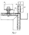
- einen Teillängsschnitt durch einen Großbehälter im Bereich des Schiebetores,
- Fig. 2
- einen Teilquerschnitt durch den Großbehälter, gleichfalls im im Bereich des Schiebetores,
- Fig. 3
- einen Teilausschnitt eines Schiebeflügels im Eckbereich zur Deckenaufhängung.
- Fig. 1
- a partial longitudinal section through a large container in the area of the sliding gate,
- Fig. 2
- a partial cross section through the large container, also in the area of the sliding gate,
- Fig. 3
- a partial section of a sliding wing in the corner area for ceiling suspension.
In der Fig. 1 ist ein Großbehälter 7 angeordnet, in dessen Decke 8 zwei parallel und mit Abstand zueinander verlaufende Führungsschienen 12 festgelegt sind, in denen mittels Laufrollen 13 zwei ein Schiebetor bildende Schiebeflügel 1,2 verschiebbar gelagert sind.A large container 7 is arranged in FIG whose
Die Schiebeflügel 1,2, sind mit gekröpften Aufhängern 15 versehen, an deren freier Endseite die in den Führungsschienen 12 laufenden Laufrollen 13 gelagert sind.The sliding
Weiter ist an der Decke 8 ein Brandschott 10 festgelegt, das zwischen den mit Abstand zueinander angeordneten Schiebeflügeln 1,2 verläuft, sich über die gesamte Breite des Schiebetores erstreckt und in den zwischen den Schiebeflügeln 1,2 gebildeten Zwischenraum hineinragt.Furthermore, a
Sowohl die Schiebeflügel 1,2 auf ihren dem Brandschott 10 zugewandten Seiten, als auch dieses auf seinen den Schiebeflügeln 1,2 zugewandten Seiten, sind mit Dämmschichtbildnern 14 versehen, deren Volumen sich im Brandfall, das heißt bei Erhöhung der Umgebungstemperatur, vergrößern, und den vorhandenen Zwischenraum zwischen dem Brandschott 10 und den jeweiligen Schiebeflügeln 1,2 vollständig ausfüllen, so daß ein Durchdringen von Wärme in das Innere des Großbehälters verhindert wird.Both the sliding
Des weiteren sind im Bereich der Führungsschienen 12 sowohl außenseitig als auch im Innern des Großbehälters 7 Dämmplatten 16,17 vorgesehen, die die Schiebeflügel 1,2 in ihrem oberen Bereich überlappen, wobei zumindest die Schiebeflügel 1,2 auf ihren den Dämmplatten 16,17 zugewandten Seiten ebenfalls mit Dämmschichtbildner 14 versehen sind.Furthermore, 7
Im Bereich des Bodens 9 des Großbehälters 7, und zwar fluchtend zum Brandschott 10 ist ein sich über die Schiebetorbreite erstreckendes Sperrteil 11 angeordnet, das in den unteren Zwischenraum, der zwischen den Schiebeflügeln 1,2 gebildet ist, hineinragt.In the area of the bottom 9 of the large container 7, namely in alignment with the
Das Sperrteil 11 weist ebenso wie das Brandschott 10 auf seinen den Schiebeflügeln 1,2 zugewandten Seiten Dämmschichtbildner auf.The blocking
Derartige Dämmschichtbildner sind auch in den Bereichen der Schiebeflügel 1,2 vorgesehen, die von Schwellen 20,21 überdeckt werden, wobei die Schwelle 20 außenseitig des Großbehälters und die Schwelle 21 innenseitig angeordnet ist.Such insulating layer formers are also provided in the areas of the sliding
Wie die Figur 2 sehr deutlich zeigt, sind die Schiebeflügel 1,2 an den in Schließstellung einander zugewandten Längsseiten mit Winkelleisten 3 versehen, die sich über die gesamte Höhe erstrecken und die sich in Schließstellung des Schiebetores im Überlappungsbereich übergreifen.As FIG. 2 shows very clearly, the
Die Winkelleisten 3 sind dabei so geformt, daß sich ein abgewinkelter Schenkel parallel und mit Abstand zum zugeordneten Schiebeflügel 1,2 erstreckt, wobei dieser Schenkel einen Teil des Schiebeflügels 1,2 überdeckt und sich über dessen gesamte Höhe erstreckt.The
Der Schenkel der Winkelleiste 3 des jeweils anderen Schiebeflügels 1,2 ragt in den Spalt 6, der von einem Schiebeflügel 1,2 und der diesem zugeordnten, daran befestigen freien Schenkel der Winkelleiste 3 gebildet wird.The leg of the
Dabei liegen die parallel zueinander verlaufenden Schenkel der jeweiligen Winkelleisten 3 sowohl mit Abstand zueinander als auch mit Abstand zu dem jeweils anderen Schiebeflügel 1,2.The legs of the
Dadurch wird ein labyrinthartiger Durchgang geschaffen, in dem auf die Winkelleisten 3 bzw. auf die Schiebeflügel 1,2 aufgeklebte Dämmschichtbildner 4,5 angeordnet sind. Wie bereits beschrieben wird durch die im Brandfall auftretende Wärme das Volumen des Dämmschichtbildners vergrößert, so daß der Spalt 6 gegenüber von außen eindringender Hitze abgedichtet ist.This creates a labyrinthine passage in which
Im Überlappungsbereich der geschlossenen Schiebeflügel 1,2 ist stirnseitig jeweils eine Verschlußplatte 18 vorgesehen, die mit Dämmschichtbildnern 19 versehen ist. Im Funktionsfall füllen diese die verbleibenden Räume zwischen den Verschlußplatten 18 einerseits und dem Brandschott 10 und den Dämmplatten 16,17 andererseits, so daß absolut sicher gewährleistet ist, daß auch durch diesen Bereich keine Hitze in den Innenraum des Großbehälters 7 dringen kann.
Auf der der zugeordneten Laufschiene 12 zugewandten Stirnseite jedes Schiebeflügels 1,2 ist ein Kastenaufsatz 22 vorgesehen, der gleichfalls mit Dämmschichtbildnern 19 ummantelt ist, die im Bedarfsfall die angrenzenden Räume feuerbeständig ausfüllen.In the overlap area of the closed sliding
On the end face of each sliding
Claims (5)
- A large, preferably transportable container (7) which can be closed by a refractory sliding door, in which the sliding door has a plurality of sliding door leaves (1, 2), of which at least one is provided at its top with rollers (13) guided in a guide rail (12) arranged at the ceiling (8) of the large container (7), wherein extending parallel to the sliding door leaves (1, 2) over the entire width of the sliding door, a fire wall (10) is arranged at the ceiling (8) of the large container (7), and a barrier portion (11) is arranged in the region of the bottom (9) in alignment with the fire wall (10), the fire wall (10) and the barrier portion (11) each projecting into a gap formed by the spaced arrangement of the sliding door leaves (1, 2), and the fire wall (10) and the sliding door leaves (1, 2), on the mutually facing sides in the overlap region, and the barrier portion (11), at least on the sides towards the sliding door leaves (1, 2), are provided with insulating layer-forming components (14).
- A large container according to claim 1 characterised in that provided on the outside in the region of the guide rail (12) is an insulating plate (16) which extends at least over the entire width of the sliding door and which covers over the upper region of the outside of a sliding door leaf (2), the mutually facing sides of the sliding door leaf (2) and the insulating plate (16) being provided with insulating layer-forming component (14).
- A large container according to claim 1 characterised in that the outer sliding door leaf is provided on its end towards the runner rail (12) with a box fitment (22) which is encased with insulating layer-forming component (19), the ends each being provided with a closure plate (18).
- A large container according to claim 1 characterised in that the sliding door leaves (1, 2) are each provided in the overlap region with angle strips (3) which engage over each other in the closure position and on which insulating layer-forming components (5) are fixed.
- A large container according to claim 4 characterised in that each angle strip (3) has a limb which extends parallel and at a spacing relative to the associated sliding door leaf (1, 2) and which partially covers over the sliding door leaf (1, 2) and which extends over the entire height thereof, wherein in the closure position of the sliding door the limb of the respective other angle strip (3) lies in the gap formed by the sliding door leaf (1, 2) and the limb of the associated angle strip (3).
Applications Claiming Priority (3)
| Application Number | Priority Date | Filing Date | Title |
|---|---|---|---|
| DE4104704 | 1991-02-15 | ||
| DE4104704A DE4104704A1 (en) | 1991-02-15 | 1991-02-15 | LOCKABLE WITH A FIRE-RESISTANT SLIDING GATE, PREFERABLY TRANSPORTABLE LARGE CONTAINER |
| PCT/DE1992/000109 WO1992014901A1 (en) | 1991-02-15 | 1992-02-12 | Large, preferably transportable container which can be closed by a refractory sliding door |
Publications (2)
| Publication Number | Publication Date |
|---|---|
| EP0529020A1 EP0529020A1 (en) | 1993-03-03 |
| EP0529020B1 true EP0529020B1 (en) | 1994-06-01 |
Family
ID=6425136
Family Applications (1)
| Application Number | Title | Priority Date | Filing Date |
|---|---|---|---|
| EP92904661A Expired - Lifetime EP0529020B1 (en) | 1991-02-15 | 1992-02-12 | Large, preferably transportable container which can be closed by a refractory sliding door |
Country Status (6)
| Country | Link |
|---|---|
| US (1) | US5305901A (en) |
| EP (1) | EP0529020B1 (en) |
| AT (1) | ATE106494T1 (en) |
| DE (2) | DE4104704A1 (en) |
| ES (1) | ES2053354T3 (en) |
| WO (1) | WO1992014901A1 (en) |
Cited By (1)
| Publication number | Priority date | Publication date | Assignee | Title |
|---|---|---|---|---|
| DE19511071C1 (en) * | 1995-03-25 | 1996-07-18 | Hoffmann Indbau Gmbh | Container with sliding panels |
Families Citing this family (17)
| Publication number | Priority date | Publication date | Assignee | Title |
|---|---|---|---|---|
| FR2726318B1 (en) * | 1994-10-26 | 1998-03-20 | Leichle | SLIDING FIRE DOOR |
| US5554433A (en) * | 1995-02-10 | 1996-09-10 | The Bilco Company | Fire rated floor door and control system |
| US5921420A (en) * | 1997-06-06 | 1999-07-13 | Gordon; Gerald A. | Fire protective cover for liquid holding containers |
| DE19933408B4 (en) * | 1999-07-21 | 2005-10-13 | Dorma Gmbh + Co. Kg | Fire door or window |
| US6299008B1 (en) * | 1999-09-28 | 2001-10-09 | Boh Environmental, Llc | Transport and storage system |
| US6615544B1 (en) | 2000-06-21 | 2003-09-09 | Nystrom, Inc. | Fire-resistant door |
| CA2437144A1 (en) * | 2003-08-08 | 2005-02-08 | Bosik Security Containment Systems Limited | Blast-resistant panels and containers |
| GB0323796D0 (en) * | 2003-10-10 | 2003-11-12 | Bombardier Transp Gmbh | Fireproof sliding door assembly for a fire protection wall |
| US20050183354A1 (en) * | 2004-02-09 | 2005-08-25 | Tlemcani Jalil R. | Fire door |
| GB2479529B (en) * | 2010-04-12 | 2016-01-06 | Marine Systems Technology Ltd | Door and frame system |
| JP6778039B2 (en) * | 2016-07-22 | 2020-10-28 | 三協立山株式会社 | Joinery |
| US11512523B2 (en) | 2017-03-27 | 2022-11-29 | Cornellcookson, Llc | Fire rated door |
| JP6857106B2 (en) * | 2017-09-22 | 2021-04-14 | 三協立山株式会社 | sash |
| JP6873021B2 (en) * | 2017-10-10 | 2021-05-19 | Ykk Ap株式会社 | Joinery |
| JP6701318B2 (en) * | 2018-12-26 | 2020-05-27 | Ykk Ap株式会社 | Joinery |
| JP6841951B2 (en) * | 2020-03-06 | 2021-03-10 | 三協立山株式会社 | Joinery |
| DE102020117328A1 (en) * | 2020-07-01 | 2022-01-05 | Denios-Ag | Dangerous goods container |
Family Cites Families (15)
| Publication number | Priority date | Publication date | Assignee | Title |
|---|---|---|---|---|
| US2638190A (en) * | 1950-05-15 | 1953-05-12 | William C Watkins | Combined door and window |
| DE1833388U (en) * | 1960-04-09 | 1961-06-22 | Vincenzo Freschi | COMPOSITE PROFILE STRIP FOR THE MANUFACTURE OF WINDOW AND DOOR FRAMES. |
| US3111981A (en) * | 1960-11-25 | 1963-11-26 | Brunswick Corp | Floor seal |
| US3566541A (en) * | 1969-03-06 | 1971-03-02 | Rixson Inc | Protective barrier for products of combustion |
| US3685567A (en) * | 1969-09-18 | 1972-08-22 | Paul E Pemberton | Sectional fire door assembly |
| CH573526A5 (en) * | 1973-02-10 | 1976-03-15 | Polio Ets | |
| DE2431800C2 (en) * | 1974-07-02 | 1985-02-14 | Türenwerke Riexinger GmbH & Co KG, 7129 Brackenheim | Fire-resistant gate, preferably sliding gate |
| DE2613998C2 (en) * | 1976-04-01 | 1984-12-20 | Theo 5140 Erkelenz Schröders | Slidable fire protection closure |
| US4203255A (en) * | 1977-05-26 | 1980-05-20 | Cal-Wood Door | Fire-resistant composite wood structure particularly adapted for use in fire doors |
| US4248342A (en) * | 1979-09-24 | 1981-02-03 | King Paul V | Blast suppressive shielding |
| FR2485074A1 (en) * | 1980-06-20 | 1981-12-24 | Emery Alexandre | Sliding panels for door - run along tracks housed in hollow channels open along lower edges |
| DE3212640A1 (en) * | 1982-04-05 | 1983-10-13 | Türenwerke Riexinger GmbH & Co KG, 7129 Brackenheim | Sliding gate, sliding door or the like |
| NL8301327A (en) * | 1983-04-15 | 1984-11-01 | Groeneveld H D Beheer | Fire-resistant door for oil or gas drilling platform - has frame seal edges, emitting foam at temps. 150-180 deg. C |
| SE457815C (en) * | 1984-07-04 | 1996-04-11 | Svensk Doerrteknik Ab | Curvature and fire impact counteracting, at least externally identifiable as a wooden door |
| DE3918158C1 (en) * | 1989-06-03 | 1990-07-26 | Flachglas Ag, 8510 Fuerth, De |
-
1991
- 1991-02-15 DE DE4104704A patent/DE4104704A1/en not_active Withdrawn
-
1992
- 1992-02-12 US US07/923,983 patent/US5305901A/en not_active Expired - Fee Related
- 1992-02-12 WO PCT/DE1992/000109 patent/WO1992014901A1/en active IP Right Grant
- 1992-02-12 ES ES92904661T patent/ES2053354T3/en not_active Expired - Lifetime
- 1992-02-12 AT AT92904661T patent/ATE106494T1/en active
- 1992-02-12 EP EP92904661A patent/EP0529020B1/en not_active Expired - Lifetime
- 1992-02-12 DE DE59200201T patent/DE59200201D1/en not_active Expired - Fee Related
Cited By (1)
| Publication number | Priority date | Publication date | Assignee | Title |
|---|---|---|---|---|
| DE19511071C1 (en) * | 1995-03-25 | 1996-07-18 | Hoffmann Indbau Gmbh | Container with sliding panels |
Also Published As
| Publication number | Publication date |
|---|---|
| ATE106494T1 (en) | 1994-06-15 |
| US5305901A (en) | 1994-04-26 |
| EP0529020A1 (en) | 1993-03-03 |
| WO1992014901A1 (en) | 1992-09-03 |
| DE4104704A1 (en) | 1992-08-20 |
| DE59200201D1 (en) | 1994-07-07 |
| ES2053354T3 (en) | 1994-07-16 |
Similar Documents
| Publication | Publication Date | Title |
|---|---|---|
| EP0529020B1 (en) | Large, preferably transportable container which can be closed by a refractory sliding door | |
| EP0882169B1 (en) | Fire door | |
| EP0549769B1 (en) | Fire-resistant glass partition | |
| DE3934983C2 (en) | ||
| DE3803317A1 (en) | Fire-protection passenger-lift door | |
| AT394881B (en) | SECTIONAL GATE | |
| DE2547818A1 (en) | Wall fire sealed doorway closure - has frame mounted movable sealing element overlapping conveyor opening all round | |
| DE3815444A1 (en) | Fireproof counter-ceiling | |
| DE1954555A1 (en) | Fire protection gate, preferably consisting of a metal housing and fire protection plates arranged in this | |
| DE102015107035B4 (en) | Brandschutzschiebetor | |
| DE2420548A1 (en) | Fireproof door or other fire screen wall-sealing element - comprising self-supporting asbestos-cement panels encased in two concentric sheet metal boxes | |
| EP3486370B1 (en) | Devices and methods for enclosing a route | |
| DE2914467A1 (en) | Steel-reinforced glass fire protection door - has frame comprising shells fitting one inside the other | |
| EP0388774B1 (en) | Fire protection door | |
| DE2613998A1 (en) | Sliding fire door with self sealing guide slot - has slot lined with sealing material which expands when heated | |
| DE7422521U (en) | Fire-resistant gate, preferably sliding gate | |
| DE3820767C1 (en) | Door leaf of a fire door | |
| DE2348854A1 (en) | Fire barrier for openings in walls - has guide frame and panel made from asbestos and silicate combined material | |
| DE2942559A1 (en) | Fire-damping door construction - has metal leaf frame and layers of material expanded by heat in peripheral portion | |
| DE3247879A1 (en) | Door leaf of a fireproof door | |
| DE20316085U1 (en) | Fire-proof separating wall for producing fire-protected regions in buildings comprises door elements and wall elements inserted in a framework of vertical and horizontal profiles | |
| DE2431800A1 (en) | Fire-resistant sliding-door - includes sectional door-panel and heat-resistant insulating material inside | |
| DE10210255A1 (en) | Fire resistant partition wall assembly for electrical distributor has divided casing with hinged access doors forming secondary partition wall | |
| DE2002438A1 (en) | Partition wall system and method for ventilating rooms formed by partition wall systems | |
| DE2462510A1 (en) | Sliding fire resistant door leaf - with even number of fire resistant panel layers between metal sheets |
Legal Events
| Date | Code | Title | Description |
|---|---|---|---|
| PUAI | Public reference made under article 153(3) epc to a published international application that has entered the european phase |
Free format text: ORIGINAL CODE: 0009012 |
|
| 17P | Request for examination filed |
Effective date: 19920723 |
|
| AK | Designated contracting states |
Kind code of ref document: A1 Designated state(s): AT BE CH DE ES FR GB IT LI NL SE |
|
| 17Q | First examination report despatched |
Effective date: 19930624 |
|
| ITF | It: translation for a ep patent filed |
Owner name: STUDIO INGG. FISCHETTI & WEBER |
|
| GRAA | (expected) grant |
Free format text: ORIGINAL CODE: 0009210 |
|
| AK | Designated contracting states |
Kind code of ref document: B1 Designated state(s): AT BE CH DE ES FR GB IT LI NL SE |
|
| REF | Corresponds to: |
Ref document number: 106494 Country of ref document: AT Date of ref document: 19940615 Kind code of ref document: T |
|
| REF | Corresponds to: |
Ref document number: 59200201 Country of ref document: DE Date of ref document: 19940707 |
|
| GBT | Gb: translation of ep patent filed (gb section 77(6)(a)/1977) |
Effective date: 19940615 |
|
| REG | Reference to a national code |
Ref country code: ES Ref legal event code: FG2A Ref document number: 2053354 Country of ref document: ES Kind code of ref document: T3 |
|
| ET | Fr: translation filed | ||
| EAL | Se: european patent in force in sweden |
Ref document number: 92904661.3 |
|
| PG25 | Lapsed in a contracting state [announced via postgrant information from national office to epo] |
Ref country code: AT Effective date: 19950212 |
|
| PG25 | Lapsed in a contracting state [announced via postgrant information from national office to epo] |
Ref country code: SE Effective date: 19950213 Ref country code: ES Free format text: LAPSE BECAUSE OF NON-PAYMENT OF DUE FEES Effective date: 19950213 |
|
| PG25 | Lapsed in a contracting state [announced via postgrant information from national office to epo] |
Ref country code: LI Effective date: 19950228 Ref country code: CH Effective date: 19950228 Ref country code: BE Effective date: 19950228 |
|
| PLBE | No opposition filed within time limit |
Free format text: ORIGINAL CODE: 0009261 |
|
| STAA | Information on the status of an ep patent application or granted ep patent |
Free format text: STATUS: NO OPPOSITION FILED WITHIN TIME LIMIT |
|
| 26N | No opposition filed | ||
| BERE | Be: lapsed |
Owner name: P&D SYSTEMTECHNIK G.M.B.H. Effective date: 19950228 |
|
| EUG | Se: european patent has lapsed |
Ref document number: 92904661.3 |
|
| PG25 | Lapsed in a contracting state [announced via postgrant information from national office to epo] |
Ref country code: GB Effective date: 19960212 |
|
| GBPC | Gb: european patent ceased through non-payment of renewal fee |
Effective date: 19960212 |
|
| PGFP | Annual fee paid to national office [announced via postgrant information from national office to epo] |
Ref country code: DE Payment date: 20020207 Year of fee payment: 11 |
|
| PGFP | Annual fee paid to national office [announced via postgrant information from national office to epo] |
Ref country code: NL Payment date: 20020214 Year of fee payment: 11 |
|
| PGFP | Annual fee paid to national office [announced via postgrant information from national office to epo] |
Ref country code: FR Payment date: 20020221 Year of fee payment: 11 |
|
| PG25 | Lapsed in a contracting state [announced via postgrant information from national office to epo] |
Ref country code: NL Free format text: LAPSE BECAUSE OF NON-PAYMENT OF DUE FEES Effective date: 20030901 |
|
| PG25 | Lapsed in a contracting state [announced via postgrant information from national office to epo] |
Ref country code: DE Free format text: LAPSE BECAUSE OF NON-PAYMENT OF DUE FEES Effective date: 20030902 |
|
| PG25 | Lapsed in a contracting state [announced via postgrant information from national office to epo] |
Ref country code: FR Free format text: LAPSE BECAUSE OF NON-PAYMENT OF DUE FEES Effective date: 20031031 |
|
| NLV4 | Nl: lapsed or anulled due to non-payment of the annual fee |
Effective date: 20030901 |
|
| REG | Reference to a national code |
Ref country code: FR Ref legal event code: ST |
|
| REG | Reference to a national code |
Ref country code: ES Ref legal event code: FD2A Effective date: 19960311 |
|
| PG25 | Lapsed in a contracting state [announced via postgrant information from national office to epo] |
Ref country code: IT Free format text: LAPSE BECAUSE OF NON-PAYMENT OF DUE FEES Effective date: 20050212 |