EP0527939B1 - Dilatation catheter assembly with cutting element - Google Patents
Dilatation catheter assembly with cutting element Download PDFInfo
- Publication number
- EP0527939B1 EP0527939B1 EP91910484A EP91910484A EP0527939B1 EP 0527939 B1 EP0527939 B1 EP 0527939B1 EP 91910484 A EP91910484 A EP 91910484A EP 91910484 A EP91910484 A EP 91910484A EP 0527939 B1 EP0527939 B1 EP 0527939B1
- Authority
- EP
- European Patent Office
- Prior art keywords
- cutting element
- assembly according
- tissue
- support
- bladder
- Prior art date
- Legal status (The legal status is an assumption and is not a legal conclusion. Google has not performed a legal analysis and makes no representation as to the accuracy of the status listed.)
- Expired - Lifetime
Links
Images

Classifications
-
- A—HUMAN NECESSITIES
- A61—MEDICAL OR VETERINARY SCIENCE; HYGIENE
- A61B—DIAGNOSIS; SURGERY; IDENTIFICATION
- A61B18/00—Surgical instruments, devices or methods for transferring non-mechanical forms of energy to or from the body
- A61B18/04—Surgical instruments, devices or methods for transferring non-mechanical forms of energy to or from the body by heating
- A61B18/08—Surgical instruments, devices or methods for transferring non-mechanical forms of energy to or from the body by heating by means of electrically-heated probes
-
- A—HUMAN NECESSITIES
- A61—MEDICAL OR VETERINARY SCIENCE; HYGIENE
- A61B—DIAGNOSIS; SURGERY; IDENTIFICATION
- A61B18/00—Surgical instruments, devices or methods for transferring non-mechanical forms of energy to or from the body
- A61B18/04—Surgical instruments, devices or methods for transferring non-mechanical forms of energy to or from the body by heating
- A61B18/12—Surgical instruments, devices or methods for transferring non-mechanical forms of energy to or from the body by heating by passing a current through the tissue to be heated, e.g. high-frequency current
- A61B18/14—Probes or electrodes therefor
- A61B18/1492—Probes or electrodes therefor having a flexible, catheter-like structure, e.g. for heart ablation
-
- A—HUMAN NECESSITIES
- A61—MEDICAL OR VETERINARY SCIENCE; HYGIENE
- A61B—DIAGNOSIS; SURGERY; IDENTIFICATION
- A61B17/00—Surgical instruments, devices or methods, e.g. tourniquets
- A61B17/22—Implements for squeezing-off ulcers or the like on the inside of inner organs of the body; Implements for scraping-out cavities of body organs, e.g. bones; Calculus removers; Calculus smashing apparatus; Apparatus for removing obstructions in blood vessels, not otherwise provided for
-
- A—HUMAN NECESSITIES
- A61—MEDICAL OR VETERINARY SCIENCE; HYGIENE
- A61B—DIAGNOSIS; SURGERY; IDENTIFICATION
- A61B17/00—Surgical instruments, devices or methods, e.g. tourniquets
- A61B17/00234—Surgical instruments, devices or methods, e.g. tourniquets for minimally invasive surgery
- A61B2017/00292—Surgical instruments, devices or methods, e.g. tourniquets for minimally invasive surgery mounted on or guided by flexible, e.g. catheter-like, means
-
- A—HUMAN NECESSITIES
- A61—MEDICAL OR VETERINARY SCIENCE; HYGIENE
- A61B—DIAGNOSIS; SURGERY; IDENTIFICATION
- A61B18/00—Surgical instruments, devices or methods for transferring non-mechanical forms of energy to or from the body
- A61B2018/00053—Mechanical features of the instrument of device
- A61B2018/00107—Coatings on the energy applicator
- A61B2018/00148—Coatings on the energy applicator with metal
-
- A—HUMAN NECESSITIES
- A61—MEDICAL OR VETERINARY SCIENCE; HYGIENE
- A61B—DIAGNOSIS; SURGERY; IDENTIFICATION
- A61B18/00—Surgical instruments, devices or methods for transferring non-mechanical forms of energy to or from the body
- A61B2018/00053—Mechanical features of the instrument of device
- A61B2018/00214—Expandable means emitting energy, e.g. by elements carried thereon
- A61B2018/0022—Balloons
-
- A—HUMAN NECESSITIES
- A61—MEDICAL OR VETERINARY SCIENCE; HYGIENE
- A61B—DIAGNOSIS; SURGERY; IDENTIFICATION
- A61B18/00—Surgical instruments, devices or methods for transferring non-mechanical forms of energy to or from the body
- A61B2018/00053—Mechanical features of the instrument of device
- A61B2018/00273—Anchoring means for temporary attachment of a device to tissue
- A61B2018/00279—Anchoring means for temporary attachment of a device to tissue deployable
- A61B2018/00285—Balloons
-
- A—HUMAN NECESSITIES
- A61—MEDICAL OR VETERINARY SCIENCE; HYGIENE
- A61B—DIAGNOSIS; SURGERY; IDENTIFICATION
- A61B18/00—Surgical instruments, devices or methods for transferring non-mechanical forms of energy to or from the body
- A61B2018/00315—Surgical instruments, devices or methods for transferring non-mechanical forms of energy to or from the body for treatment of particular body parts
- A61B2018/00345—Vascular system
- A61B2018/00351—Heart
- A61B2018/00386—Coronary vessels
-
- A—HUMAN NECESSITIES
- A61—MEDICAL OR VETERINARY SCIENCE; HYGIENE
- A61B—DIAGNOSIS; SURGERY; IDENTIFICATION
- A61B18/00—Surgical instruments, devices or methods for transferring non-mechanical forms of energy to or from the body
- A61B2018/00315—Surgical instruments, devices or methods for transferring non-mechanical forms of energy to or from the body for treatment of particular body parts
- A61B2018/00345—Vascular system
- A61B2018/00404—Blood vessels other than those in or around the heart
- A61B2018/00422—Angioplasty
-
- A—HUMAN NECESSITIES
- A61—MEDICAL OR VETERINARY SCIENCE; HYGIENE
- A61B—DIAGNOSIS; SURGERY; IDENTIFICATION
- A61B18/00—Surgical instruments, devices or methods for transferring non-mechanical forms of energy to or from the body
- A61B18/04—Surgical instruments, devices or methods for transferring non-mechanical forms of energy to or from the body by heating
- A61B18/12—Surgical instruments, devices or methods for transferring non-mechanical forms of energy to or from the body by heating by passing a current through the tissue to be heated, e.g. high-frequency current
- A61B18/1206—Generators therefor
- A61B2018/1213—Generators therefor creating an arc
-
- A—HUMAN NECESSITIES
- A61—MEDICAL OR VETERINARY SCIENCE; HYGIENE
- A61B—DIAGNOSIS; SURGERY; IDENTIFICATION
- A61B18/00—Surgical instruments, devices or methods for transferring non-mechanical forms of energy to or from the body
- A61B18/04—Surgical instruments, devices or methods for transferring non-mechanical forms of energy to or from the body by heating
- A61B18/12—Surgical instruments, devices or methods for transferring non-mechanical forms of energy to or from the body by heating by passing a current through the tissue to be heated, e.g. high-frequency current
- A61B18/1206—Generators therefor
- A61B2018/1246—Generators therefor characterised by the output polarity
- A61B2018/1253—Generators therefor characterised by the output polarity monopolar
-
- A—HUMAN NECESSITIES
- A61—MEDICAL OR VETERINARY SCIENCE; HYGIENE
- A61B—DIAGNOSIS; SURGERY; IDENTIFICATION
- A61B18/00—Surgical instruments, devices or methods for transferring non-mechanical forms of energy to or from the body
- A61B18/04—Surgical instruments, devices or methods for transferring non-mechanical forms of energy to or from the body by heating
- A61B18/12—Surgical instruments, devices or methods for transferring non-mechanical forms of energy to or from the body by heating by passing a current through the tissue to be heated, e.g. high-frequency current
- A61B18/14—Probes or electrodes therefor
- A61B2018/1405—Electrodes having a specific shape
- A61B2018/144—Wire
-
- A—HUMAN NECESSITIES
- A61—MEDICAL OR VETERINARY SCIENCE; HYGIENE
- A61M—DEVICES FOR INTRODUCING MEDIA INTO, OR ONTO, THE BODY; DEVICES FOR TRANSDUCING BODY MEDIA OR FOR TAKING MEDIA FROM THE BODY; DEVICES FOR PRODUCING OR ENDING SLEEP OR STUPOR
- A61M25/00—Catheters; Hollow probes
- A61M25/10—Balloon catheters
- A61M25/104—Balloon catheters used for angioplasty
Definitions
- the present invention relates to dilation catheter assemblies.
- Dilation catheters are used to dilate body vessels, orifices and conduits such as an artery narrowed by atherosclerotic plaque and/or fibromuscular disease or to dilate a constricted or obstructed ureter or urethra.
- Previously proposed devices basically consist of an elongate catheter having an inflatable extensible elastomeric (rubber-like) or non-extensible variety, at or near its distal end.
- a guide wire or other axial support means is often included to improve the torque control or "steerability" of the apparatus.
- dilation catheter use over conventional surgery is that it is less invasive. Nonetheless, the tissue that is stressed is often also subjected to significant trauma. As the bladder expands, it exerts pressure on the surrounding tissue, causing the tissue to compress, deform and expand. The tissue, of course, has an inherent limit of deformability. When the dilation pressure causes the tissue to deform beyond that limit, the tissue tears apart, often to form a jagged wound, with considerable damage, trauma, pain and bleeding.
- U.S. Patent 4, 799, 479, and International patent Application No. WO-A-89 01800 show use of a balloon to open up an artery and then utilizes a laser, heated wire mesh, or the like, to heat up blood trapped between the media and the plaque so that dilation will be maintained and so that a smooth wall will result.
- German Patent 3,402,573 a solid core is provided with three longitudinal slots into which respective ones of three bladder segments can be retracted.
- Each bladder segment carries a cutting member and the opposite ends of the bladder section are anchored to the exterior of the solid core so that when the bladder segment is retracted into the slot, the cutter is also retracted into the slot.
- the anchoring of the bladder segment to the core is thus essential in order to ensure that the cutter remains in a position in which it can be retracted into the corresponding slot in the core.
- the object of the present invention is to provide an improved dilation catheter assembly.
- a dilation catheter assembly comprising an elongate support having a distal end carrying a radially dilatable member adapted to be positioned longitudinally in a body conduit and having properties for dilating generally radially of the elongate support; means for dilating the dilatable member to exert dilation forces on tissue surrounding the body conduit; and a cutting element located externally of the dilatable member and carried by the support, the cutting element being movable by the dilatable member radially into contact with said tissue and operable to incise said tissue, characterised in that the dilatable member comprises a longitudinally inextensible generally cylindrical radially dilatable body operable to dilate in a generally radially symmetrical manner to a fixed volume and shape so as to exert pressure on surrounding body tissue to provide a substantially uniform tangential tension therein; thereby reducing damage to said tissue from the dilation forces.
- Figure 1 depicts a dilatation catheter assembly, generally designated 10, that may be used for dilating a body vessel or conduit, such as a ureter or urethra, to treat a blockage or other obstruction.
- the main elements of catheter assembly 10 are: an adapter 11 that defines the proximal end 12 of the assembly 10 and a site for various ports to the assembly 10; a triple lumen catheter body 13 ( Figure 2); an inflatable inextensible balloon or bladder member 15; and a cutting element 17, very preferably a radio frequency cutting element activatable by a radio frequency power source.
- the electrosurgical cutting element or electrode 17 is in the nature of a wire which runs along generally parallel to the longitudinally extending inflatable bladder 15.
- the bladder 15 is inserted longitudinally into a body conduit to the position where a surgical cut is required.
- the bladder 15 is then inflated (an inextensible bladder is used) to a desired pressure about 1 atmosphere and allowed to expand to occupy the space in the body vessel or conduit.
- Radio frequency current is then passed through the cutting element 17. This leads to the wire being moved outwardly and incising adjacent tissue in that direction.
- the pressurization and incising steps are suitably repeated (the pressure drops each time incising occurs) as many times as is necessary until the bladder 15 is fully inflated. In this way, the depth of the incision is controlled by the size chosen for the inextensible bladder 15 and tearing is avoided by making successive cuts rather than exerting a very large pressure within the bladder and overstressing the body conduit.
- the material used for the wire can be any of the materials currently used for electrosurgical cutting wires.
- the wire can be made of stainless steel or tungsten.
- one of the three lumens serves as an inflation/deflation passageway 18, a second serves as a drainage/infusion passageway, and a third carries cutting element 17.
- the inflatable balloon or bladder member 15 is of the inextensible or constant volume variety, that assumes, when expanded, a specific size and shape.
- the balloon member 15 cannot extend significantly longitudinally within a body conduit beyond its selected length. And, further, it can only extend radially to a selected radius, thus controlling the depth of the incision. Since the balloon member 15 cannot extend longitudinally, as can elastic or elastomeric balloons, it must exert the force caused by inflation of the balloon member 15 radially against an enclosing body conduit or the like.
- a radio frequency cutting element 17 it is preferred to utilize a radio frequency cutting element 17 for a number of reasons.
- a radio frequency cutting element 17 will not perform any cutting unless and until it is activated by passing a radio frequency current through it.
- accidental cuts cannot be made away from the area where cutting is desired.
- This radio frequency cutting or cauterizing technique can, thus, provide significant advantages over the use of prior art cutters in an apparatus of the nature disclosed herein.
- the balloon member 15 generally extends longitudinally along the body conduit and is generally symmetrically placed and expandable therein. In this manner, as the balloon member 15 is expanded, it exerts a substantially equal tangential tension upon the tissue defining the body conduit. This results in the incision by the cutting element 17, which would generally proceed parallel to the balloon member 15, being particularly clean. In essence, the incision when made in this manner proceeds longitudinally along the body cavity and will generally not go off at an angle as might be the case if the tangential tension in the body conduit was not substantially uniform.
- the cutting element 17 is a radio frequency cutting element and is parallel to the bladder member 15, the bladder member 15 extends longitudinally along the body conduit and is of an inextensible (non-elastic, non-elastomeric) nature and is symmetrically placed within the body cavity so that on expansion it exerts a substantially uniform tangential tension upon the tissue defining the body cavity.
- the adapter 11 serves as a site for a bladder inflation/deflation port 19 that is attached to a source of inflation medium (not shown) for inflating the bladder member 15 or a suction source (not shown) for deflating the bladder member 15.
- Port 19 has a valve 20 for regulating the inflation medium or suction, as the case may be.
- Port 19 connects into the proximal end of an inflation/deflation passageway 18 that extends from the port 19 to the bladder member 15.
- the adapter 11 also serves as a site for the drainage tube inlet/outlet port 22 and a cutting element port 23.
- the drainage port 22 is connected to the proximal end of the lumen that carries a stylet or guide wire.
- the drainage port 22 may serve as a site for removing fluid from the lumen or as a site for infusing fluid into the lumen.
- the distal end of the catheter body has a series of drain holes 24 to facilitate flushing the lumen with fluid or voiding the bladder member 15.
- a "banana plug" cutting element connector 25 is affixed to the end of the cutting element port and the cutting element 17 extends from the connector through the lumen of the catheter body 13 and exits therefrom via an aperture 26 and continues along the exterior of the bladder member 15.
- the cutting element 17 can consist of a thin wire which has an external incising edge that faces outwardly from the bladder member 15.
- the cutting element 17 may be a sharp edge, beam, or, more preferably, a radio frequency cutting or cauterizing element 17.
- the element/bladder is/are constructed (e.g., the element 17 is flexible or expandable) such that the cutting element 17 is carried on the exterior of the bladder member 15 (at least when the bladder member 15 is inflated) but is not capable of incising the bladder member 15.
- the portion of the exterior of the bladder member 15 that is exposed to the cutting element 17 may carry a protective cover (not shown) to further guard against the bladder member 15 being incised by the cutting element 17.
- the cutting element 17 may be carried at a predetermined spacing from the bladder surface or directly on the surface. When carried on the surface the cutting element 17 may be an integral part of the surface or attached to the surface. If desired the cutting element 17 may be extended/retracted manually via the connector into/out of the catheter body 13.
- the distal end of the assembly 10 includes an atromatic tip 27. Such structure may not be necessary or desirable for dilating other conduits/orifices.
- the assembly 10 may optionally include another lumen and "Foley" (Registered Trade Mark) type balloon (not shown) distally of the dilatation bladder member 15 to anchor the catheter in the bladder neck of the human body to facilitate correct positioning of the dilatation bladder member 15 and minimize the possibility of migration and displacement of the assembly 10.
- One or more of the catheter assembly components may be made of radiopaque materials to facilitate the visualization of the assembly 10 by the physician during placement of the assembly 10 in the body vessel/conduit.
- a typical surgical procedure in which the catheter assembly 10 is employed involves the following steps.
- a cytoscope is first inserted into the vessel/conduit/orifice to be dilated. Calibration devices may be inserted through the cytoscope to facilitate measuring the extent of the vessel/conduit/orifice being dilated.
- the dilatation catheter of Figure 1 is then inserted to the desired depth in the vessel/conduit.
- a cytoscope lens may then be inserted to allow visualization of the catheter and the bladder location. Fluid may be infused through the drainage tube or cytoscope to facilitate such visualization.
- the bladder member 15 is inflated. Such inflation causes the cutting element 17 to move radially outwardly as the bladder surface expands radially until the cutting element 17 contacts the surrounding tissue.
- the bladder member 15 is inextensible as mentioned previously.
- tissue is intended to include, without limitation, normal tissue, stomatic tissue, neoplastic tissue (tumors) or an obstruction such as plaque.
- tissue is intended to include, without limitation, normal tissue, stomatic tissue, neoplastic tissue (tumors) or an obstruction such as plaque.
- the inflated bladder member 15 provides the additional benefit of acting as a tamponade to reduce bleeding.
- the radio frequency cutting element 17 is such that it incises the surrounding tissue in a manner such as to cause controlled incising under the combined cutting and dilating action.
- the power through the radio frequency cutting element 17 is disconnected, if such a cutting element is used, the bladder member 15 is deflated by connecting the inflation/deflation port 19 to suction or atmospheric pressure and opening the inflation/deflation port valve 20 thereto. Deflation of the bladder member 15 results in a simultaneously radial retraction of the cutting element 17 out of contact with the tissue. Once the bladder member 15 is deflated the cutting element 17 may be retracted via the connector 25.
- the cutting element 17 may be retracted prior to complete deflation of the bladder member 15 and/or the bladder member 15 reinflated and left in place to act as a tamponade. Often it is desirable to leave the cutting element 17 in contact with the wound for a time, for example from about 10 minutes to about 2 hours, until the bleeding stops or is under control, and then to deflate the bladder member 15 and withdraw the catheter. Alternatively, the catheter can simply be withdrawn from the vessel/conduit altogether. The particular details of operation are determined by the surgeon depending upon the particular procedure being carried out and the particular person being operated upon.
- Figures 3-6 depict another dilation catheter assembly of a preferred embodiment of the invention, generally designated 29, in use. Only the distal end of the assembly 29 is shown. Adapter(s), inflation/deflation ports are not shown for convenience.
- the distal end is defined by a closed end catheter tube 32 which carries an inflatable, preferably inextensible, bladder member 33 on its exterior.
- the lumen 34 of the tube 32 is connected to the source of inflation fluid/suction, as the case may be.
- the tube 32 has a radial aperture 35 that opens into the lumen 36 of the bladder member 33.
- a pair of expandable ring-shaped members 37,38 extend around the exterior of the bladder member 33 near the distal and proximal ends thereof.
- One or more cutting elements 39 are affixed between the rings so that they extend longitudinally and outwardly therefrom.
- Figures 3 (in solid line) and 4 show the assembly 29 in its deflated state positioned within a vessel 42 partially obstructed by an obstruction 43.
- pressurized fluid is passed through catheter tube lumen 34 and aperture 35 into the bladder lumen. Inflation of the bladder member 33 in turn causes the ring members 37,38 to expand and move the cutting element(s) 39 radially outward.
- Figures 3 (phantom line), 5, and 6 show the bladder member 33 in an inflated state with the cutting element 39 incising the obstruction.
- FIG. 7 shows yet another dilation catheter assembly, generally designated 46, of a preferred embodiment of the invention.
- the assembly 46 is shown in its deflated state.
- This assembly 46 is similar in structure to assembly 29 except that the assembly 46 is housed within a sheath or introducer 47 and a cauterizing element 48 is connected to the cutting element 39.
- the sheath permits the assembly 46 to be introduced into the vessel in an unexposed manner, ejected from the end thereof for use, and retracted back into the sheath 47 after use. The ejection and retraction may be achieved by relative longitudinal movement of the sheath 47, assembly 46, or both.
- the cutting element 39 can be a radio frequency cutting element and cauterization will result along with the cutting. Also, following cutting a coagulation producing radio frequency signal can be passed through cutting element 39.
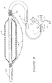
- Figure 8 illustrates an embodiment of the invention wherein the cutting element 17 can be advanced beyond the supporting surface of the bladder 15.
- the cutting element 17 has an actuator 55 attached to it in the area of the adapter 11, the actuator extending through the adapter 11.
- the surgeon can electively advance the actuator 55, thereby advancing the cutting element 17 and causing it to bow outwardly and away from the bladder 15, and when a radio frequency current is passed through it, incise further into the tissue a desired distance.
- the described apparatus for controlled surgical dilation and incision within body conduits, vessels and orifices virtually eliminates tearing and trauma caused by dilation beyond the strength of the tissue forming the body conduit, vessel or orifice being dilated.
Landscapes
- Health & Medical Sciences (AREA)
- Surgery (AREA)
- Engineering & Computer Science (AREA)
- Life Sciences & Earth Sciences (AREA)
- Biomedical Technology (AREA)
- Molecular Biology (AREA)
- Nuclear Medicine, Radiotherapy & Molecular Imaging (AREA)
- Plasma & Fusion (AREA)
- Physics & Mathematics (AREA)
- Heart & Thoracic Surgery (AREA)
- Medical Informatics (AREA)
- Otolaryngology (AREA)
- Animal Behavior & Ethology (AREA)
- General Health & Medical Sciences (AREA)
- Public Health (AREA)
- Veterinary Medicine (AREA)
- Cardiology (AREA)
- Media Introduction/Drainage Providing Device (AREA)
- Surgical Instruments (AREA)
Abstract
Description
- The present invention relates to dilation catheter assemblies.
- Dilation catheters are used to dilate body vessels, orifices and conduits such as an artery narrowed by atherosclerotic plaque and/or fibromuscular disease or to dilate a constricted or obstructed ureter or urethra. Previously proposed devices basically consist of an elongate catheter having an inflatable extensible elastomeric (rubber-like) or non-extensible variety, at or near its distal end. A guide wire or other axial support means is often included to improve the torque control or "steerability" of the apparatus.
- The major advantage of dilation catheter use over conventional surgery is that it is less invasive. Nonetheless, the tissue that is stressed is often also subjected to significant trauma. As the bladder expands, it exerts pressure on the surrounding tissue, causing the tissue to compress, deform and expand. The tissue, of course, has an inherent limit of deformability. When the dilation pressure causes the tissue to deform beyond that limit, the tissue tears apart, often to form a jagged wound, with considerable damage, trauma, pain and bleeding.
- U.S. Patent 4, 799, 479, and International patent Application No. WO-A-89 01800 show use of a balloon to open up an artery and then utilizes a laser, heated wire mesh, or the like, to heat up blood trapped between the media and the plaque so that dilation will be maintained and so that a smooth wall will result.
- In German Patent 3,402,573 a solid core is provided with three longitudinal slots into which respective ones of three bladder segments can be retracted. Each bladder segment carries a cutting member and the opposite ends of the bladder section are anchored to the exterior of the solid core so that when the bladder segment is retracted into the slot, the cutter is also retracted into the slot. The anchoring of the bladder segment to the core is thus essential in order to ensure that the cutter remains in a position in which it can be retracted into the corresponding slot in the core.
- The object of the present invention is to provide an improved dilation catheter assembly.
- According to the present invention there is provided a dilation catheter assembly, comprising an elongate support having a distal end carrying a radially dilatable member adapted to be positioned longitudinally in a body conduit and having properties for dilating generally radially of the elongate support; means for dilating the dilatable member to exert dilation forces on tissue surrounding the body conduit; and a cutting element located externally of the dilatable member and carried by the support, the cutting element being movable by the dilatable member radially into contact with said tissue and operable to incise said tissue, characterised in that the dilatable member comprises a longitudinally inextensible generally cylindrical radially dilatable body operable to dilate in a generally radially symmetrical manner to a fixed volume and shape so as to exert pressure on surrounding body tissue to provide a substantially uniform tangential tension therein; thereby reducing damage to said tissue from the dilation forces.
- Dilation catheter assemblies embodying the present invention will now be described by way of example with reference to the accompanying diagrammatic drawings, wherein like numbers denote like parts throughout and in which:
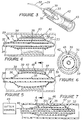
- Figure 1 is a partly cross-sectional isometric view of one embodiment of the invention catheter;
- Figure 2 is a cross-sectional view taken along line 2-2 of Figure 1;
- Figure 3 is a prospective, schematic sectional view of a portion of another embodiment of the invention catheter positioned within a body conduit;
- Figure 4 is a sectional, side view of the embodiment of Figure 3 in its deflated state;
- Figure 5 is a sectional side view of the embodiment of Figure 3 in its inflated state;
- Figure 6 is a cross-sectional view along line 6-6 of Figure 5;
- Figure 7 is a sectional elevational view of another embodiment of the invention; and
- Figure 8 is a view similar to Figure 1 and which includes means for selectively incising more deeply into a patient's tissue.
- Figure 1 depicts a dilatation catheter assembly, generally designated 10, that may be used for dilating a body vessel or conduit, such as a ureter or urethra, to treat a blockage or other obstruction. The main elements of
catheter assembly 10 are: anadapter 11 that defines theproximal end 12 of theassembly 10 and a site for various ports to theassembly 10; a triple lumen catheter body 13 (Figure 2); an inflatable inextensible balloon orbladder member 15; and acutting element 17, very preferably a radio frequency cutting element activatable by a radio frequency power source. The electrosurgical cutting element orelectrode 17 is in the nature of a wire which runs along generally parallel to the longitudinally extendinginflatable bladder 15. In use, thebladder 15 is inserted longitudinally into a body conduit to the position where a surgical cut is required. Thebladder 15 is then inflated (an inextensible bladder is used) to a desired pressure about 1 atmosphere and allowed to expand to occupy the space in the body vessel or conduit. Radio frequency current is then passed through thecutting element 17. This leads to the wire being moved outwardly and incising adjacent tissue in that direction. Thereafter, the pressurization and incising steps are suitably repeated (the pressure drops each time incising occurs) as many times as is necessary until thebladder 15 is fully inflated. In this way, the depth of the incision is controlled by the size chosen for theinextensible bladder 15 and tearing is avoided by making successive cuts rather than exerting a very large pressure within the bladder and overstressing the body conduit. - The material used for the wire can be any of the materials currently used for electrosurgical cutting wires. For example, the wire can be made of stainless steel or tungsten. A sheath with a slit in it, the slit facing away from the
bladder 15, surrounds thecutting element 17. As seen in Figure 2, one of the three lumens serves as an inflation/deflation passageway 18, a second serves as a drainage/infusion passageway, and a third carriescutting element 17. - In accordance with the present invention the inflatable balloon or
bladder member 15 is of the inextensible or constant volume variety, that assumes, when expanded, a specific size and shape. Thus, theballoon member 15 cannot extend significantly longitudinally within a body conduit beyond its selected length. And, further, it can only extend radially to a selected radius, thus controlling the depth of the incision. Since theballoon member 15 cannot extend longitudinally, as can elastic or elastomeric balloons, it must exert the force caused by inflation of theballoon member 15 radially against an enclosing body conduit or the like. In contrast, if an elastic or elastomeric balloon is expanded within a body conduit which has one portion particularly narrowed and particularly resistant to expansion, the balloon will simply elongate rather than acting radially outwardly against the constriction. What is happening is a balance of forces in the balloon which then expands in the direction of least resistance. - In accordance with the present invention it is preferred to utilize a radio
frequency cutting element 17 for a number of reasons. One reason is that a radiofrequency cutting element 17 will not perform any cutting unless and until it is activated by passing a radio frequency current through it. As a result, accidental cuts cannot be made away from the area where cutting is desired. And, with proper control cutting can be very sharply defined leading to a clean incision without tearing. This radio frequency cutting or cauterizing technique can, thus, provide significant advantages over the use of prior art cutters in an apparatus of the nature disclosed herein. - In accordance with the present invention the
balloon member 15 generally extends longitudinally along the body conduit and is generally symmetrically placed and expandable therein. In this manner, as theballoon member 15 is expanded, it exerts a substantially equal tangential tension upon the tissue defining the body conduit. This results in the incision by thecutting element 17, which would generally proceed parallel to theballoon member 15, being particularly clean. In essence, the incision when made in this manner proceeds longitudinally along the body cavity and will generally not go off at an angle as might be the case if the tangential tension in the body conduit was not substantially uniform. - In accordance with the most preferred embodiment of the present invention the
cutting element 17 is a radio frequency cutting element and is parallel to thebladder member 15, thebladder member 15 extends longitudinally along the body conduit and is of an inextensible (non-elastic, non-elastomeric) nature and is symmetrically placed within the body cavity so that on expansion it exerts a substantially uniform tangential tension upon the tissue defining the body cavity. This allows all of the advantages of the present invention to be realized at one and the same time. - The
adapter 11 serves as a site for a bladder inflation/deflation port 19 that is attached to a source of inflation medium (not shown) for inflating thebladder member 15 or a suction source (not shown) for deflating thebladder member 15.Port 19 has avalve 20 for regulating the inflation medium or suction, as the case may be.Port 19 connects into the proximal end of an inflation/deflation passageway 18 that extends from theport 19 to thebladder member 15. Theadapter 11 also serves as a site for the drainage tube inlet/outlet port 22 and acutting element port 23. Thedrainage port 22 is connected to the proximal end of the lumen that carries a stylet or guide wire. Thedrainage port 22 may serve as a site for removing fluid from the lumen or as a site for infusing fluid into the lumen. The distal end of the catheter body has a series ofdrain holes 24 to facilitate flushing the lumen with fluid or voiding thebladder member 15. A "banana plug"cutting element connector 25 is affixed to the end of the cutting element port and thecutting element 17 extends from the connector through the lumen of thecatheter body 13 and exits therefrom via anaperture 26 and continues along the exterior of thebladder member 15. Thecutting element 17 can consist of a thin wire which has an external incising edge that faces outwardly from thebladder member 15. Alternatively, the cuttingelement 17 may be a sharp edge, beam, or, more preferably, a radio frequency cutting or cauterizingelement 17. The element/bladder is/are constructed (e.g., theelement 17 is flexible or expandable) such that the cuttingelement 17 is carried on the exterior of the bladder member 15 (at least when thebladder member 15 is inflated) but is not capable of incising thebladder member 15. If desired, the portion of the exterior of thebladder member 15 that is exposed to the cuttingelement 17 may carry a protective cover (not shown) to further guard against thebladder member 15 being incised by the cuttingelement 17. The cuttingelement 17 may be carried at a predetermined spacing from the bladder surface or directly on the surface. When carried on the surface the cuttingelement 17 may be an integral part of the surface or attached to the surface. If desired the cuttingelement 17 may be extended/retracted manually via the connector into/out of thecatheter body 13. - For use in urethral dilatation the distal end of the
assembly 10 includes anatromatic tip 27. Such structure may not be necessary or desirable for dilating other conduits/orifices. For urethral dilatation, theassembly 10 may optionally include another lumen and "Foley" (Registered Trade Mark) type balloon (not shown) distally of thedilatation bladder member 15 to anchor the catheter in the bladder neck of the human body to facilitate correct positioning of thedilatation bladder member 15 and minimize the possibility of migration and displacement of theassembly 10. - One or more of the catheter assembly components may be made of radiopaque materials to facilitate the visualization of the
assembly 10 by the physician during placement of theassembly 10 in the body vessel/conduit. - A typical surgical procedure in which the
catheter assembly 10 is employed involves the following steps. A cytoscope is first inserted into the vessel/conduit/orifice to be dilated. Calibration devices may be inserted through the cytoscope to facilitate measuring the extent of the vessel/conduit/orifice being dilated. The dilatation catheter of Figure 1 is then inserted to the desired depth in the vessel/conduit. A cytoscope lens may then be inserted to allow visualization of the catheter and the bladder location. Fluid may be infused through the drainage tube or cytoscope to facilitate such visualization. Once in position, thebladder member 15 is inflated. Such inflation causes the cuttingelement 17 to move radially outwardly as the bladder surface expands radially until the cuttingelement 17 contacts the surrounding tissue. In accordance with a preferred embodiment of the invention thebladder member 15 is inextensible as mentioned previously. - As used herein the term "tissue" is intended to include, without limitation, normal tissue, stomatic tissue, neoplastic tissue (tumors) or an obstruction such as plaque. Continued radial expansion of the
bladder member 15 positions the cuttingelement 17 and causes thebladder member 15 to exert pressure on the tissue thereby subjecting the tissue to a substantially uniform tangential tension. If the preferred radiofrequency cutting element 17 is utilized a radio frequency current is passed through it. This combined cutting and dilating action results in the tissue being expanded without being torn due to a buildup of excess stresses within the tissue. Instead, the tissue is cut in a clean, concentrated, generally longitudinal fashion by the cuttingelement 17 and the dilatation does not uncontrollably tear the tissue and cause excessive trauma and bleeding. Theinflated bladder member 15 provides the additional benefit of acting as a tamponade to reduce bleeding. The radiofrequency cutting element 17 is such that it incises the surrounding tissue in a manner such as to cause controlled incising under the combined cutting and dilating action. - After the vessel/conduit/orifice tissue is incised and dilated and the blockage/obstruction is relieved, the power through the radio
frequency cutting element 17 is disconnected, if such a cutting element is used, thebladder member 15 is deflated by connecting the inflation/deflation port 19 to suction or atmospheric pressure and opening the inflation/deflation port valve 20 thereto. Deflation of thebladder member 15 results in a simultaneously radial retraction of the cuttingelement 17 out of contact with the tissue. Once thebladder member 15 is deflated the cuttingelement 17 may be retracted via theconnector 25. If desired, the cuttingelement 17 may be retracted prior to complete deflation of thebladder member 15 and/or thebladder member 15 reinflated and left in place to act as a tamponade. Often it is desirable to leave the cuttingelement 17 in contact with the wound for a time, for example from about 10 minutes to about 2 hours, until the bleeding stops or is under control, and then to deflate thebladder member 15 and withdraw the catheter. Alternatively, the catheter can simply be withdrawn from the vessel/conduit altogether. The particular details of operation are determined by the surgeon depending upon the particular procedure being carried out and the particular person being operated upon. - Figures 3-6 depict another dilation catheter assembly of a preferred embodiment of the invention, generally designated 29, in use. Only the distal end of the
assembly 29 is shown. Adapter(s), inflation/deflation ports are not shown for convenience. The distal end is defined by a closedend catheter tube 32 which carries an inflatable, preferably inextensible,bladder member 33 on its exterior. Thelumen 34 of thetube 32 is connected to the source of inflation fluid/suction, as the case may be. Thetube 32 has aradial aperture 35 that opens into thelumen 36 of thebladder member 33. A pair of expandable ring-shapedmembers bladder member 33 near the distal and proximal ends thereof. One or morecutting elements 39 are affixed between the rings so that they extend longitudinally and outwardly therefrom. - Figures 3 (in solid line) and 4 show the
assembly 29 in its deflated state positioned within avessel 42 partially obstructed by anobstruction 43. In order to inflate thebladder member 33, pressurized fluid is passed throughcatheter tube lumen 34 andaperture 35 into the bladder lumen. Inflation of thebladder member 33 in turn causes thering members bladder member 33 in an inflated state with the cuttingelement 39 incising the obstruction. - Figure 7 shows yet another dilation catheter assembly, generally designated 46, of a preferred embodiment of the invention. The
assembly 46 is shown in its deflated state. Thisassembly 46 is similar in structure toassembly 29 except that theassembly 46 is housed within a sheath orintroducer 47 and acauterizing element 48 is connected to the cuttingelement 39. The sheath permits theassembly 46 to be introduced into the vessel in an unexposed manner, ejected from the end thereof for use, and retracted back into thesheath 47 after use. The ejection and retraction may be achieved by relative longitudinal movement of thesheath 47,assembly 46, or both. The cuttingelement 39 can be a radio frequency cutting element and cauterization will result along with the cutting. Also, following cutting a coagulation producing radio frequency signal can be passed through cuttingelement 39. - Figure 8 illustrates an embodiment of the invention wherein the cutting
element 17 can be advanced beyond the supporting surface of thebladder 15. In the embodiment of Figure 8 the cuttingelement 17 has anactuator 55 attached to it in the area of theadapter 11, the actuator extending through theadapter 11. After incision has been completed using thebladder 15, that is, after thebladder 15 has been fully extended and the cuttingelement 17 has cut as deeply as it will when supported by thebladder 15, the surgeon can electively advance theactuator 55, thereby advancing the cuttingelement 17 and causing it to bow outwardly and away from thebladder 15, and when a radio frequency current is passed through it, incise further into the tissue a desired distance. - The described apparatus for controlled surgical dilation and incision within body conduits, vessels and orifices, virtually eliminates tearing and trauma caused by dilation beyond the strength of the tissue forming the body conduit, vessel or orifice being dilated.
Claims (16)
- A dilation catheter assembly (10), comprising an elongate support (13) having a distal end carrying a radially dilatable member (15) adapted to be positioned longitudinally in a body conduit and having properties for dilating generally radially of the elongate support (13); means for dilating the dilatable member to exert dilation forces on tissue surrounding the body conduit; and a cutting element (17) located externally of the dilatable member (15) and carried by the support (13), the cutting element (17) being movable by the dilatable member (15) radially into contact with said tissue and operable to incise said tissue, characterised in that the dilatable member (15) comprises a longitudinally inextensible generally cylindrical radially dilatable body operable to dilate in a generally radially symmetrical manner to a fixed volume and shape so as to exert pressure on surrounding body tissue to provide a substantially uniform tangential tension therein; thereby reducing damage to said tissue from the dilation forces.
- An assembly according to Claim 1 characterised in that the dilatable member (15) is an inflatable bladder.
- An assembly according to Claim 1 or to Claim 2 characterised in that the cutting element (17), is responsive to a radio frequency electrical signal to incise said tissue.
- An assembly according to any preceding claim characterised in that the cutting element (17) is disposed in a plane including the elongate axis of the support.
- An assembly according to any preceding claim characterised in that the cutting element (17) is permanently affixed to the exterior surface of the dilatable member (15).
- An assembly according to any one of Claims 1 to 4 characterised in that the cutting element (17) is removably carried on the exterior of the dilatable member (15).
- An assembly according to any one of Claims 1 to 4 characterised in that wherein the cutting element (17) is an integral component of the dilatable member (15).
- An assembly according to any preceding claim characterised in that the cutting element (17) comprises a thin wire.
- An assembly according to any preceding claim characterised by an open ended sheath (42), in which the support (13) is housed, from which the support (13) may be deployed for use and into which the support (13) may be retracted after use.
- An assembly according to any one of Claims 1 to 4 characterised in that the cutting element (17) comprises a wire disposed to extend generally longitudinally of the support (13) a first portion of the wire being rigid with the support (13) and a second portion of the wire being in a movable relationship with the support (13).
- An assembly according to Claim 10 characterised by means disposed between the cutting element (17) and the dilatable member (15), for directing energy from the cutting element (17) away from dilatable member and toward the tissue.
- An assembly according to Claim 11 characterised in that the directing means includes electrical insulation disposed along the cutting element (17) between the cutting element (17) and dilatable member (15).
- An assembly according to Claim 12 characterised in that the insulation forms a sleeve around the cutting element (17) and portions of the sleeve are removed along the cutting element (17) to direct the energy toward the tissue.
- An assembly according to any preceding claim characterised by means for maintaining a tensile force on the cutting element.
- An assembly according to Claim 14 characterised in that portions of the assembly (10) define a lumen and a hole extending from the lumen exteriorly of the assembly; the cutting element (17) has a proximal end and a distal end; with one of said ends of the cutting element (17) extending through the hole into the lumen of the catheter.
- An assembly according to Claim 14 or to Claim 15 characterised in that the maintaining means comprises a tension spring with a first portion having a fixed relationship with the support (13) and a second portion having a fixed relationship with the other end of the cutting element (17).
Applications Claiming Priority (3)
| Application Number | Priority Date | Filing Date | Title |
|---|---|---|---|
| US52214890A | 1990-05-11 | 1990-05-11 | |
| US522148 | 1990-05-11 | ||
| PCT/US1991/002857 WO1991017714A1 (en) | 1990-05-11 | 1991-04-25 | Dilatation catheter assembly with cutting element |
Publications (3)
| Publication Number | Publication Date |
|---|---|
| EP0527939A1 EP0527939A1 (en) | 1993-02-24 |
| EP0527939A4 EP0527939A4 (en) | 1994-01-12 |
| EP0527939B1 true EP0527939B1 (en) | 1997-07-09 |
Family
ID=24079659
Family Applications (1)
| Application Number | Title | Priority Date | Filing Date |
|---|---|---|---|
| EP91910484A Expired - Lifetime EP0527939B1 (en) | 1990-05-11 | 1991-04-25 | Dilatation catheter assembly with cutting element |
Country Status (5)
| Country | Link |
|---|---|
| EP (1) | EP0527939B1 (en) |
| JP (1) | JP3466183B2 (en) |
| CA (1) | CA2082621C (en) |
| DE (1) | DE69126780T2 (en) |
| WO (1) | WO1991017714A1 (en) |
Families Citing this family (51)
| Publication number | Priority date | Publication date | Assignee | Title |
|---|---|---|---|---|
| US5779698A (en) | 1989-01-18 | 1998-07-14 | Applied Medical Resources Corporation | Angioplasty catheter system and method for making same |
| EP0569548B1 (en) * | 1991-01-29 | 1997-10-29 | Applied Medical Resources, Inc. | Catheter with electrosurgical cutter |
| US5836868A (en) * | 1992-11-13 | 1998-11-17 | Scimed Life Systems, Inc. | Expandable intravascular occlusion material removal devices and methods of use |
| US5490859A (en) * | 1992-11-13 | 1996-02-13 | Scimed Life Systems, Inc. | Expandable intravascular occlusion material removal devices and methods of use |
| US5792157A (en) * | 1992-11-13 | 1998-08-11 | Scimed Life Systems, Inc. | Expandable intravascular occlusion material removal devices and methods of use |
| US5501694A (en) * | 1992-11-13 | 1996-03-26 | Scimed Life Systems, Inc. | Expandable intravascular occlusion material removal devices and methods of use |
| US5897567A (en) * | 1993-04-29 | 1999-04-27 | Scimed Life Systems, Inc. | Expandable intravascular occlusion material removal devices and methods of use |
| CA2118886C (en) * | 1993-05-07 | 1998-12-08 | Dennis Vigil | Method and apparatus for dilatation of a stenotic vessel |
| US6743217B2 (en) | 1994-05-13 | 2004-06-01 | Scimed Life Systems, Inc. | Apparatus for performing diagnostic and therapeutic modalities in the biliary tree |
| US5547469A (en) | 1994-05-13 | 1996-08-20 | Boston Scientific Corporation | Apparatus for performing diagnostic and therapeutic modalities in the biliary tree |
| CA2157697C (en) * | 1995-01-10 | 2007-03-13 | Banning Gray Lary | Vascular incisor/dilator |
| JPH11262527A (en) * | 1998-03-17 | 1999-09-28 | Buaayu:Kk | Blood vessel brossage balloon catheter |
| US6579300B2 (en) | 2001-01-18 | 2003-06-17 | Scimed Life Systems, Inc. | Steerable sphincterotome and methods for cannulation, papillotomy and sphincterotomy |
| JP4345478B2 (en) * | 2001-08-08 | 2009-10-14 | 株式会社カネカ | Dilatation catheter |
| US7186237B2 (en) * | 2002-02-14 | 2007-03-06 | Avantec Vascular Corporation | Ballon catheter for creating a longitudinal channel in a lesion and method |
| JP2003310762A (en) * | 2002-02-19 | 2003-11-05 | Kawasumi Lab Inc | Balloon adaptor and balloon catheter with the same |
| US7632288B2 (en) | 2003-05-12 | 2009-12-15 | Boston Scientific Scimed, Inc. | Cutting balloon catheter with improved pushability |
| US7758604B2 (en) | 2003-05-29 | 2010-07-20 | Boston Scientific Scimed, Inc. | Cutting balloon catheter with improved balloon configuration |
| US7780626B2 (en) | 2003-08-08 | 2010-08-24 | Boston Scientific Scimed, Inc. | Catheter shaft for regulation of inflation and deflation |
| US7887557B2 (en) | 2003-08-14 | 2011-02-15 | Boston Scientific Scimed, Inc. | Catheter having a cutting balloon including multiple cavities or multiple channels |
| US9050437B2 (en) | 2004-03-04 | 2015-06-09 | YMED, Inc. | Positioning device for ostial lesions |
| US7780715B2 (en) | 2004-03-04 | 2010-08-24 | Y Med, Inc. | Vessel treatment devices |
| US7766951B2 (en) | 2004-03-04 | 2010-08-03 | Y Med, Inc. | Vessel treatment devices |
| US7754047B2 (en) | 2004-04-08 | 2010-07-13 | Boston Scientific Scimed, Inc. | Cutting balloon catheter and method for blade mounting |
| US8747389B2 (en) | 2004-04-21 | 2014-06-10 | Acclarent, Inc. | Systems for treating disorders of the ear, nose and throat |
| US20060063973A1 (en) | 2004-04-21 | 2006-03-23 | Acclarent, Inc. | Methods and apparatus for treating disorders of the ear, nose and throat |
| US20070167682A1 (en) | 2004-04-21 | 2007-07-19 | Acclarent, Inc. | Endoscopic methods and devices for transnasal procedures |
| US7559925B2 (en) | 2006-09-15 | 2009-07-14 | Acclarent Inc. | Methods and devices for facilitating visualization in a surgical environment |
| US9399121B2 (en) | 2004-04-21 | 2016-07-26 | Acclarent, Inc. | Systems and methods for transnasal dilation of passageways in the ear, nose or throat |
| US10188413B1 (en) | 2004-04-21 | 2019-01-29 | Acclarent, Inc. | Deflectable guide catheters and related methods |
| US8702626B1 (en) | 2004-04-21 | 2014-04-22 | Acclarent, Inc. | Guidewires for performing image guided procedures |
| US20190314620A1 (en) | 2004-04-21 | 2019-10-17 | Acclarent, Inc. | Apparatus and methods for dilating and modifying ostia of paranasal sinuses and other intranasal or paranasal structures |
| US7803150B2 (en) | 2004-04-21 | 2010-09-28 | Acclarent, Inc. | Devices, systems and methods useable for treating sinusitis |
| US8894614B2 (en) | 2004-04-21 | 2014-11-25 | Acclarent, Inc. | Devices, systems and methods useable for treating frontal sinusitis |
| US20060004323A1 (en) | 2004-04-21 | 2006-01-05 | Exploramed Nc1, Inc. | Apparatus and methods for dilating and modifying ostia of paranasal sinuses and other intranasal or paranasal structures |
| US7566319B2 (en) | 2004-04-21 | 2009-07-28 | Boston Scientific Scimed, Inc. | Traction balloon |
| US7654997B2 (en) | 2004-04-21 | 2010-02-02 | Acclarent, Inc. | Devices, systems and methods for diagnosing and treating sinusitus and other disorders of the ears, nose and/or throat |
| US8038691B2 (en) | 2004-11-12 | 2011-10-18 | Boston Scientific Scimed, Inc. | Cutting balloon catheter having flexible atherotomes |
| US20060184191A1 (en) | 2005-02-11 | 2006-08-17 | Boston Scientific Scimed, Inc. | Cutting balloon catheter having increased flexibility regions |
| US8951225B2 (en) | 2005-06-10 | 2015-02-10 | Acclarent, Inc. | Catheters with non-removable guide members useable for treatment of sinusitis |
| ITMI20051965A1 (en) * | 2005-10-18 | 2007-04-19 | Innovamedica S R L | DEVICE FOR ENDOSCOPIC PAINTING |
| US7704248B2 (en) | 2005-12-21 | 2010-04-27 | Boston Scientific Scimed, Inc. | Ablation device with compression balloon |
| US8486025B2 (en) | 2006-05-11 | 2013-07-16 | Ronald J. Solar | Systems and methods for treating a vessel using focused force |
| JP4973084B2 (en) * | 2006-09-15 | 2012-07-11 | 株式会社カネカ | Medical device for body cavity insertion |
| JP4539629B2 (en) * | 2006-09-15 | 2010-09-08 | 株式会社カネカ | Medical device for body cavity insertion |
| KR101643907B1 (en) | 2008-09-18 | 2016-07-29 | 아클라런트, 인코포레이션 | Methods and apparatus for treating disorders of the ear nose and throat |
| JP5600745B2 (en) * | 2010-08-30 | 2014-10-01 | 株式会社グツドマン | Dilatation catheter |
| AU2011226821B2 (en) * | 2010-10-06 | 2015-09-17 | Rex Medical, L.P. | Cutting wire assembly for use with a catheter |
| JP2012196320A (en) * | 2011-03-22 | 2012-10-18 | Nipro Corp | Balloon catheter |
| US10561438B2 (en) * | 2015-10-30 | 2020-02-18 | C.R. Bard, Inc. | Scoring balloon with translating scoring wires |
| JP6769905B2 (en) * | 2017-03-30 | 2020-10-14 | テルモ株式会社 | Medical long body |
Family Cites Families (8)
| Publication number | Priority date | Publication date | Assignee | Title |
|---|---|---|---|---|
| DE2426781C3 (en) * | 1974-06-01 | 1984-08-16 | Meinhard Dr.med. 8520 Erlangen Classen | Device for severing the narrowed sphincter muscle at the mouth of the bile duct in the duodenum |
| US4273128A (en) * | 1980-01-14 | 1981-06-16 | Lary Banning G | Coronary cutting and dilating instrument |
| DE3402573A1 (en) * | 1983-07-23 | 1985-08-22 | Werner Dr.med. 4330 Mülheim Schubert | Balloon dilation apparatus with a cutting tool on a primarily single-lumen multi-purpose catheter |
| US4799479A (en) * | 1984-10-24 | 1989-01-24 | The Beth Israel Hospital Association | Method and apparatus for angioplasty |
| FR2594322A1 (en) * | 1986-02-17 | 1987-08-21 | Cleef Jean Francois Van | Composite needle for single-pole electrocoagulation |
| US4709698A (en) * | 1986-05-14 | 1987-12-01 | Thomas J. Fogarty | Heatable dilation catheter |
| US4808164A (en) * | 1987-08-24 | 1989-02-28 | Progressive Angioplasty Systems, Inc. | Catheter for balloon angioplasty |
| DE3738429A1 (en) * | 1987-11-12 | 1989-05-24 | Osypka Peter | DEVICE FOR EXTENDING AND / OR OPENING BLOOD VESSELS |
-
1991
- 1991-04-25 CA CA002082621A patent/CA2082621C/en not_active Expired - Lifetime
- 1991-04-25 DE DE69126780T patent/DE69126780T2/en not_active Expired - Fee Related
- 1991-04-25 JP JP51014591A patent/JP3466183B2/en not_active Expired - Fee Related
- 1991-04-25 WO PCT/US1991/002857 patent/WO1991017714A1/en active IP Right Grant
- 1991-04-25 EP EP91910484A patent/EP0527939B1/en not_active Expired - Lifetime
Also Published As
| Publication number | Publication date |
|---|---|
| CA2082621C (en) | 2002-07-09 |
| DE69126780T2 (en) | 1998-02-19 |
| JP3466183B2 (en) | 2003-11-10 |
| JPH05506805A (en) | 1993-10-07 |
| DE69126780D1 (en) | 1997-08-14 |
| EP0527939A1 (en) | 1993-02-24 |
| CA2082621A1 (en) | 1991-11-12 |
| WO1991017714A1 (en) | 1991-11-28 |
| EP0527939A4 (en) | 1994-01-12 |
Similar Documents
| Publication | Publication Date | Title |
|---|---|---|
| EP0527939B1 (en) | Dilatation catheter assembly with cutting element | |
| US5628746A (en) | Dilatation catheter assembly with cutting element and method of using the same | |
| US5904679A (en) | Catheter with electrosurgical cutter | |
| WO1990007909A1 (en) | Dilatation catheter assembly with cutting element | |
| US5779698A (en) | Angioplasty catheter system and method for making same | |
| US6258108B1 (en) | Incisor-dilator with tapered balloon | |
| US5616149A (en) | Balloon catheter with cutting edge | |
| US5697944A (en) | Universal dilator with expandable incisor | |
| US5713913A (en) | Device and method for transecting a coronary artery | |
| US5792158A (en) | University dilator with expandable incisor | |
| JP3359543B2 (en) | A device for perforating perfusion channels from blood vessels inside the patient's myocardium | |
| JP4170904B2 (en) | Split balloon, catheter, blade | |
| US5176693A (en) | Balloon expandable atherectomy cutter | |
| JP4504349B2 (en) | Cutting device and stenosis incision device | |
| JP3425363B2 (en) | Sheath for stent delivery system and method of use | |
| EP0565796B1 (en) | Stenosis dilatation device | |
| EP0820784A2 (en) | Balloon catheter and methods of use | |
| WO2004093941A2 (en) | Cutting balloon catheter converter | |
| EP0942766A1 (en) | Multiple balloon stent delivery catheter and method | |
| EP1210959B1 (en) | Method and device for use in micro-invasive surgical procedures, and guide catheter and valve unit for a device for use in micro-invasive surgical procedures | |
| EP0569548B1 (en) | Catheter with electrosurgical cutter |
Legal Events
| Date | Code | Title | Description |
|---|---|---|---|
| PUAI | Public reference made under article 153(3) epc to a published international application that has entered the european phase |
Free format text: ORIGINAL CODE: 0009012 |
|
| 17P | Request for examination filed |
Effective date: 19921023 |
|
| AK | Designated contracting states |
Kind code of ref document: A1 Designated state(s): DE FR GB |
|
| A4 | Supplementary search report drawn up and despatched |
Effective date: 19931129 |
|
| AK | Designated contracting states |
Kind code of ref document: A4 Designated state(s): DE FR GB |
|
| 17Q | First examination report despatched |
Effective date: 19950321 |
|
| GRAG | Despatch of communication of intention to grant |
Free format text: ORIGINAL CODE: EPIDOS AGRA |
|
| GRAH | Despatch of communication of intention to grant a patent |
Free format text: ORIGINAL CODE: EPIDOS IGRA |
|
| GRAH | Despatch of communication of intention to grant a patent |
Free format text: ORIGINAL CODE: EPIDOS IGRA |
|
| GRAA | (expected) grant |
Free format text: ORIGINAL CODE: 0009210 |
|
| AK | Designated contracting states |
Kind code of ref document: B1 Designated state(s): DE FR GB |
|
| REF | Corresponds to: |
Ref document number: 69126780 Country of ref document: DE Date of ref document: 19970814 |
|
| ET | Fr: translation filed | ||
| PLBE | No opposition filed within time limit |
Free format text: ORIGINAL CODE: 0009261 |
|
| STAA | Information on the status of an ep patent application or granted ep patent |
Free format text: STATUS: NO OPPOSITION FILED WITHIN TIME LIMIT |
|
| 26N | No opposition filed | ||
| REG | Reference to a national code |
Ref country code: GB Ref legal event code: IF02 |
|
| PGFP | Annual fee paid to national office [announced via postgrant information from national office to epo] |
Ref country code: FR Payment date: 20090417 Year of fee payment: 19 Ref country code: DE Payment date: 20090429 Year of fee payment: 19 |
|
| PGFP | Annual fee paid to national office [announced via postgrant information from national office to epo] |
Ref country code: GB Payment date: 20090429 Year of fee payment: 19 |
|
| GBPC | Gb: european patent ceased through non-payment of renewal fee |
Effective date: 20100425 |
|
| REG | Reference to a national code |
Ref country code: FR Ref legal event code: ST Effective date: 20101230 |
|
| PG25 | Lapsed in a contracting state [announced via postgrant information from national office to epo] |
Ref country code: DE Free format text: LAPSE BECAUSE OF NON-PAYMENT OF DUE FEES Effective date: 20101103 |
|
| PG25 | Lapsed in a contracting state [announced via postgrant information from national office to epo] |
Ref country code: GB Free format text: LAPSE BECAUSE OF NON-PAYMENT OF DUE FEES Effective date: 20100425 |
|
| PG25 | Lapsed in a contracting state [announced via postgrant information from national office to epo] |
Ref country code: FR Free format text: LAPSE BECAUSE OF NON-PAYMENT OF DUE FEES Effective date: 20100430 |