JP4170904B2 - Split balloon, catheter, blade - Google Patents
Split balloon, catheter, blade Download PDFInfo
- Publication number
- JP4170904B2 JP4170904B2 JP2003522612A JP2003522612A JP4170904B2 JP 4170904 B2 JP4170904 B2 JP 4170904B2 JP 2003522612 A JP2003522612 A JP 2003522612A JP 2003522612 A JP2003522612 A JP 2003522612A JP 4170904 B2 JP4170904 B2 JP 4170904B2
- Authority
- JP
- Japan
- Prior art keywords
- blade
- balloon
- stenosis
- base member
- catheter
- Prior art date
- Legal status (The legal status is an assumption and is not a legal conclusion. Google has not performed a legal analysis and makes no representation as to the accuracy of the status listed.)
- Expired - Fee Related
Links
Images


Classifications
-
- A—HUMAN NECESSITIES
- A61—MEDICAL OR VETERINARY SCIENCE; HYGIENE
- A61B—DIAGNOSIS; SURGERY; IDENTIFICATION
- A61B17/00—Surgical instruments, devices or methods, e.g. tourniquets
- A61B17/32—Surgical cutting instruments
- A61B17/3205—Excision instruments
- A61B17/3207—Atherectomy devices working by cutting or abrading; Similar devices specially adapted for non-vascular obstructions
- A61B17/320725—Atherectomy devices working by cutting or abrading; Similar devices specially adapted for non-vascular obstructions with radially expandable cutting or abrading elements
-
- A—HUMAN NECESSITIES
- A61—MEDICAL OR VETERINARY SCIENCE; HYGIENE
- A61B—DIAGNOSIS; SURGERY; IDENTIFICATION
- A61B17/00—Surgical instruments, devices or methods, e.g. tourniquets
- A61B17/22—Implements for squeezing-off ulcers or the like on the inside of inner organs of the body; Implements for scraping-out cavities of body organs, e.g. bones; Calculus removers; Calculus smashing apparatus; Apparatus for removing obstructions in blood vessels, not otherwise provided for
- A61B2017/22051—Implements for squeezing-off ulcers or the like on the inside of inner organs of the body; Implements for scraping-out cavities of body organs, e.g. bones; Calculus removers; Calculus smashing apparatus; Apparatus for removing obstructions in blood vessels, not otherwise provided for with an inflatable part, e.g. balloon, for positioning, blocking, or immobilisation
- A61B2017/22061—Implements for squeezing-off ulcers or the like on the inside of inner organs of the body; Implements for scraping-out cavities of body organs, e.g. bones; Calculus removers; Calculus smashing apparatus; Apparatus for removing obstructions in blood vessels, not otherwise provided for with an inflatable part, e.g. balloon, for positioning, blocking, or immobilisation for spreading elements apart
-
- A—HUMAN NECESSITIES
- A61—MEDICAL OR VETERINARY SCIENCE; HYGIENE
- A61M—DEVICES FOR INTRODUCING MEDIA INTO, OR ONTO, THE BODY; DEVICES FOR TRANSDUCING BODY MEDIA OR FOR TAKING MEDIA FROM THE BODY; DEVICES FOR PRODUCING OR ENDING SLEEP OR STUPOR
- A61M25/00—Catheters; Hollow probes
- A61M25/10—Balloon catheters
- A61M2025/1043—Balloon catheters with special features or adapted for special applications
- A61M2025/1086—Balloon catheters with special features or adapted for special applications having a special balloon surface topography, e.g. pores, protuberances, spikes or grooves
Landscapes
- Health & Medical Sciences (AREA)
- Surgery (AREA)
- Life Sciences & Earth Sciences (AREA)
- Medical Informatics (AREA)
- Nuclear Medicine, Radiotherapy & Molecular Imaging (AREA)
- Engineering & Computer Science (AREA)
- Biomedical Technology (AREA)
- Heart & Thoracic Surgery (AREA)
- Vascular Medicine (AREA)
- Molecular Biology (AREA)
- Animal Behavior & Ethology (AREA)
- General Health & Medical Sciences (AREA)
- Public Health (AREA)
- Veterinary Medicine (AREA)
- Media Introduction/Drainage Providing Device (AREA)
- Materials For Medical Uses (AREA)
Abstract
Description
本発明は概ね医療器具に関する。特に、本発明は、患者の脈管構造にある狭窄の切開および拡張に有用な侵襲的外科手術器具に関する。本発明は特に、排他的ではないが、その後の狭窄の切開を容易にするため、バルーン・カテーテル・ブレードでの狭窄の切開に有用である。 The present invention generally relates to medical devices. In particular, the present invention relates to invasive surgical instruments useful for incision and expansion of stenosis in a patient's vasculature. The present invention is particularly, but not exclusively, useful for stenosis incisions with balloon catheter blades to facilitate subsequent stenosis incisions.
人間の動脈の遮断は、種々の重篤な合併症を引き起こすことがある。こうなるのは、動脈の遮断が患部動脈の血流を減少させるからであり、血液供給に頼る組織の損傷をもたらすことがあるからである。例えば、遮断が心臓自体に血液を供給する動脈内にある場合は、心臓発作を引き起こすかもしれない。 Blockage of human arteries can cause a variety of serious complications. This is because blockage of the arteries reduces blood flow in the affected artery and can result in tissue damage that relies on blood supply. For example, if the blockage is in an artery that supplies blood to the heart itself, it may cause a heart attack.
このような動脈の遮断は、狭窄とも呼ばれ、通常は動脈の内壁にアテローム斑が蓄積することによって引き起こされる。実際、このような狭窄には、1本の動脈内に隣接して発生するものもある。その結果、動脈が部分的に、あるいは完全にも遮断される可能性がある。このような遮断に伴う危険の結果、狭窄治療のために幾つかの方法および処置が開発されている。このような方法の一つは、可膨脹性バルーンを使用して遮断動脈を拡張する血管形成処置である。典型的な可膨脹性血管形成器具が、例えば「DILATION CATHETER」と題した発明に関してBhateその他に発行された米国特許第4,896,669号で開示されている。Bhateその他の血管形成器具は、狭窄に通して配置するため、患者の末梢動脈に挿入可能な可膨脹性血管形成バルーンを含む。血管形成バルーンは、いったん配置したら、次に膨脹させ、動脈の内壁に当てて狭窄を平らにし、それによって動脈の血流を改善させる。 Such blockage of the artery, also called stenosis, is usually caused by the accumulation of atheroma plaques on the inner wall of the artery. In fact, some of these stenosis may occur adjacent to one artery. As a result, the artery can be partially or completely blocked. As a result of the risks associated with such blockage, several methods and procedures have been developed for the treatment of stenosis. One such method is an angioplasty procedure that uses an inflatable balloon to dilate the blocked artery. A typical inflatable angioplasty device is disclosed, for example, in US Pat. No. 4,896,669 issued to Bhate et al. With respect to the invention entitled “DILATION CATHETER”. Bhate et al.'S angioplasty device includes an inflatable angioplasty balloon that can be inserted into a patient's peripheral artery for placement through a stenosis. Once deployed, the angioplasty balloon is then inflated and applied against the inner wall of the artery to flatten the stenosis, thereby improving arterial blood flow.
血管形成バルーンは、狭窄治療で広く受容されている。しかし、最近の研究によると、狭窄拡張の有効性は、狭窄を生成している物質を最初に、または同時に切開することにより強化される。その結果、拡張処置中に狭窄を切開するための切刃、つまり動脈刀を伴う血管形成バルーンを装備するよう、近年、開発されている。例えば、本発明の譲渡人に譲渡され、「BALLOON CATHETER WITH CUTTING EDGE」と題したBarathに帰される米国特許第5,196,024号で開示された器具は、バルーンの表面上に長手方向に装着された幾つかの動脈刀を有する可膨脹性血管形成バルーンである。 Angioplasty balloons are widely accepted for stenosis treatment. However, according to recent studies, the effectiveness of stenosis dilation is enhanced by first or simultaneously incising the material producing the stenosis. As a result, it has recently been developed to equip an angioplasty balloon with a cutting edge, ie an arterial knife, for incising a stenosis during an expansion procedure. For example, the instrument disclosed in US Pat. No. 5,196,024 assigned to the assignee of the present invention and attributed to Barath entitled “BALLOON CATHETER WITH CUTTING EDGE” is mounted longitudinally on the surface of the balloon. An inflatable angioplasty balloon with several arterial knives.
Barathのバルーンを膨脹したら、動脈刀は、バルーンが膨脹するにつれ、狭窄物質の表面に一連の長手方向の切開を引き起こし、狭窄を拡張する。このような切開の結果、狭窄の平坦化がさらに容易になり、拡張中に動脈を損傷する可能性が低下する。しかし、一般に、狭窄の表面は平坦でなく、波打ち、無数の頂と谷を含む。したがって、血管形成バルーンの表面に装着された1つの長い連続的ブレードでの狭窄部切開は、不均一になり得る。特に、狭窄部表面の頂を効果的に切開する間に、狭窄部表面に存在する谷の切開が問題になることがある。したがって、狭窄部の小さい部分のみが正確に切開されるということが生じ得る。さらに、長い連続的ブレードは、カテーテルの可撓性を低下させ、患者の脈管構造を通したカテーテルの案内がさらに困難になる。 Once the Barath balloon is inflated, the arterial knife expands the stenosis by causing a series of longitudinal incisions on the surface of the stenotic material as the balloon is inflated. As a result of such an incision, the flattening of the stenosis becomes easier and the possibility of damaging the artery during dilatation is reduced. However, in general, the surface of the stenosis is not flat and includes undulations, countless peaks and valleys. Thus, a stenotic incision with one long continuous blade attached to the surface of the angioplasty balloon can be non-uniform. In particular, during the effective incision of the top of the stenosis surface, the incision of a valley present on the stenosis surface may be a problem. Accordingly, it may occur that only a small portion of the stenosis is accurately incised. Furthermore, long continuous blades reduce the flexibility of the catheter and make it more difficult to guide the catheter through the patient's vasculature.
以上を鑑みて、患者の血管にある狭窄部の頂と谷との両方を切開する器具を提供することが、本発明の目的である。バルーンの膨脹時に、狭窄部の表面にほぼ一致する効果的な切刃を有する血管形成バルーンのブレード・ユニットを提供することが、本発明のさらなる目的である。患者の脈管構造を通して狭窄部位まで容易に案内するのに十分な可撓性を有する狭窄部切開用器具を提供することが、本発明のさらに別の目的である。製造が比較的単純で、容易に使用でき、比較的費用効果が高い血管狭窄部切開用器具を提供することが、本発明の別の目的である。 In view of the above, it is an object of the present invention to provide an instrument for incising both the top and valley of a stenosis in a patient's blood vessel. It is a further object of the present invention to provide an angioplasty balloon blade unit having an effective cutting edge that substantially conforms to the surface of the stenosis when the balloon is inflated. It is yet another object of the present invention to provide a stenosis incision instrument that is flexible enough to be easily guided through a patient's vasculature to a stenosis site. It is another object of the present invention to provide a vascular stenosis incision instrument that is relatively simple to manufacture, easy to use, and relatively cost effective.
本発明では、患者の脈管構造にある狭窄部を切開する器具は、ベース部材に装着され、その上で整列した複数のブレード・セグメントを含む。ベース部材は、可膨脹性血管形成バルーンの外面に装着される。したがって、バルーンを患者の脈管構造に挿入し、狭窄部に配置して、その後に膨脹させる場合、ブレード・セグメントは、狭窄部の表面に効果的に一致する効果的切刃を形成する。切刃が狭窄部の頂および谷にこのように一致できるので、狭窄部をほぼ均一な深さまで切開することができる。 In the present invention, an instrument for incising a stenosis in a patient's vasculature includes a plurality of blade segments mounted on and aligned with a base member. The base member is attached to the outer surface of the inflatable angioplasty balloon. Thus, when the balloon is inserted into the patient's vasculature, placed in the stenosis, and then inflated, the blade segment forms an effective cutting edge that effectively matches the surface of the stenosis. Since the cutting edge can coincide with the top and valley of the stenosis in this way, the stenosis can be incised to a substantially uniform depth.
詳細には、狭窄部の表面に一致できる効果的な切刃を確立するため、隣接するブレード・セグメント間で相対運動を可能にするパターンで、ブレード・セグメントをベース部材に取り付ける。本発明では、個々の各ブレード・セグメントは概ね細長く、伸張方向でブレード軸線を画定する。各ブレード・セグメントを、ベース部材に装着し、ブレード軸線が少なくとも1つの他のブレード・セグメントのブレード軸線とほぼ平行か、ほぼ同一線上にある状態で配向することが好ましい。さらに、各ブレード・セグメントの遠位部分は、(パターンの最遠位端にあるブレード・セグメントを除いて)次に近いブレード・セグメントの近位部分と並置され、好ましくはこれと接触する。したがって、各ブレード・セグメントは、軸方向で次に近いブレード・セグメントから偏る。 Specifically, the blade segments are attached to the base member in a pattern that allows relative movement between adjacent blade segments to establish an effective cutting edge that can conform to the surface of the constriction. In the present invention, each individual blade segment is generally elongated and defines a blade axis in the direction of extension. Each blade segment is preferably attached to the base member and oriented with the blade axis substantially parallel or collinear with the blade axis of at least one other blade segment. Further, the distal portion of each blade segment is juxtaposed with, preferably in contact with, the proximal portion of the next closest blade segment (except for the blade segment at the most distal end of the pattern). Thus, each blade segment is offset from the next closest blade segment in the axial direction.
本発明では、ベース部材は、薄いポリウレタン材料の細片などの弾性材料で作成され、これによってベース部材は、バルーンの膨脹または収縮中に血管形成バルーンの表面とともに変形することができる。ベース部材の一方側を、血管形成バルーンの外面に接着することが好ましい。本発明では、伸張方向にバルーン軸線を画定する細長い血管形成バルーンを一般に使用する。ベース部材も細長く、ベース部材の伸張方向がバルーン軸線に平行な状態で、バルーンの外面に装着することが好ましい。本発明では、ブレード・セグメントを、各ブレード軸線がベース部材の伸張方向にほぼ平行な状態で、ベース部材に装着する。さらに、各ブレード・セグメントに、鋭利な刃を生成するテーパ区間を形成する。各ブレード・セグメントは、ベース部材上にて、各ブレード・セグメントの鋭利な刃が1本の連続的な切断線にほぼ沿っている状態で配向することが好ましい。 In the present invention, the base member is made of an elastic material, such as a strip of thin polyurethane material, so that the base member can deform with the surface of the angioplasty balloon during inflation or deflation of the balloon. It is preferable to adhere one side of the base member to the outer surface of the angioplasty balloon. The present invention generally uses an elongated angioplasty balloon that defines a balloon axis in the stretch direction. The base member is also elongated and is preferably attached to the outer surface of the balloon in a state where the extending direction of the base member is parallel to the balloon axis. In the present invention, the blade segments are attached to the base member with each blade axis being substantially parallel to the direction of extension of the base member. In addition, each blade segment is formed with a tapered section that produces a sharp blade. Each blade segment is preferably oriented on the base member with the sharp edges of each blade segment approximately along one continuous cutting line.
使用時には、血管形成バルーン、ベース部材およびブレード・セグメントを有するカテーテルを、患者の脈管構造に挿入する。次に、血管形成バルーンが、治療を必要とする狭窄部に通して配置されるまで、カテーテルを脈管構造内で前進させる。そのため、ガイドワイヤを使用して、機械的通路を確立し、治療部位までカテーテルを補助することができる。次に、バルーンをゆっくり膨脹させ、ブレード・セグメントが狭窄部の表面に接触するまで、バルーンの外面、ベース部材およびブレード・セグメントがバルーンの軸線から半径方向で一緒に外側へと移動できるようにする。 In use, a catheter having an angioplasty balloon, a base member and a blade segment is inserted into the patient's vasculature. The catheter is then advanced through the vasculature until the angioplasty balloon is placed through the stenosis requiring treatment. As such, a guidewire can be used to establish a mechanical pathway and assist the catheter to the treatment site. The balloon is then inflated slowly, allowing the outer surface of the balloon, the base member and the blade segment to move radially together outward from the balloon axis until the blade segment contacts the constriction surface. .
狭窄部の表面に接触したら、各ブレード・セグメントの鋭利な刃が狭窄部に切り込み、切開部を生成する。次に、ブレード・セグメントが狭窄部内に効果的に埋め込まれるまで、バルーンの膨脹を継続する。最終的に、バルーンの外面および弾性ベース部材が、狭窄部表面と接触し、これと一致する。ブレードがセグメントに分割され、ブレード・セグメント間で相対運動できるよう、ベース部材上に配置されているので、ブレード・セグメントは、バルーンおよびベース部材が狭窄部表面に一致するのを妨げない。また、ブレード・セグメント間の相対運動により、ブレード・セグメントは、狭窄部表面に一致する効果的な切刃を形成することができ、その結果、狭窄部の表面の頂および谷に沿ってほぼ均一な深さのほぼ連続的な切開部になる。 Once in contact with the surface of the stenosis, the sharp blade of each blade segment cuts into the stenosis, creating an incision. The balloon is then inflated until the blade segment is effectively embedded within the constriction. Eventually, the outer surface of the balloon and the elastic base member come into contact with and coincide with the stenosis surface. The blade segment does not prevent the balloon and base member from conforming to the constriction surface because the blade is divided into segments and positioned on the base member so as to allow relative movement between the blade segments. Also, the relative movement between the blade segments allows the blade segments to form an effective cutting edge that coincides with the constriction surface, resulting in a substantially uniform along the top and valley of the constriction surface. This results in an almost continuous incision with a certain depth.
切開後、所望に応じて血管形成バルーンをさらに膨脹させ、狭窄部を拡張することができる。いずれの場合も、血管形成バルーンは、その後に収縮させ、狭窄部からブレード・セグメントを後退させる。収縮したら、バルーンおよびブレード・セグメントは、別の狭窄部を治療するために再配置するか、患者から取り出すことができる。 After incision, the angioplasty balloon can be further inflated as desired to expand the stenosis. In either case, the angioplasty balloon is then deflated and the blade segment is retracted from the stenosis. Once deflated, the balloon and blade segment can be repositioned to remove another stenosis or removed from the patient.
本発明の新規の特徴、さらに本発明自体は、その構造および動作の両方について、添付図面を、添付の説明と組み合わせて考慮することにより、最もよく理解され、ここで同様の参照文字は同様の部品を指す。 The novel features of the present invention, as well as the invention itself, are best understood by considering the accompanying drawings in conjunction with the accompanying description, both in terms of structure and operation, wherein like reference characters are Refers to parts.
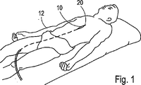
最初に図1を参照すると、狭窄部を切開し、拡張する器具10が、手術のために患者12の体内に配置されて図示されている。図2に示すように、器具10は、細長く、バルーン軸線16を画定する血管形成バルーン14を含む。図示のように、ルーメン18を設けて、バルーン14をガイドワイヤ20(図1に図示)に沿って辿り、バルーン14を膨脹/収縮できるようにする。本発明では、ブレード・ユニット22およびブレード・ユニット24などの1つまたは複数のブレード・ユニットを、血管形成バルーン14の外面に装着する。
Referring initially to FIG. 1, an
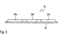
次に図2、図3および図4を相互参照すると、ブレード・ユニット22は、ベース部材26および複数のブレード・セグメント28a、28bおよび28cを含むことが理解される。3つのブレード・セグメント28a、28b、28cしか図示されていないが、本発明ではブレード・ユニット22が任意の数のブレード・セグメント28a、28b、28cを含むことができることが理解される。各ブレード・セグメント28a、28b、28cは、ステンレス鋼などの硬質な生体適合性材料で作成することが好ましい。
2, 3 and 4, it will be appreciated that the
図示のように、各ブレード・セグメント28a、28b、28cは、一般に細長く、伸張方向にブレード軸線30を画定する。好ましい実施形態では、各ブレード・セグメント28a、28b、28cをベース部材26に装着し、ブレード軸線30a、30b、30cが少なくとも1つの他のブレード・セグメント28a、28b、28cのブレード軸線30a、30b、30cとほぼ平行か、ほぼ同一直線上になる状態で配向する。ブレード・セグメント28a、28b、28cのベース部材26への取付けは、予備形成したブレード・セグメント28a、28b、28cを接着剤でベース部材26に接着するなど、当技術分野で知られている任意の方法を使用して遂行することができる。
As shown, each
次に図4を参照すると、ブレード・セグメント28a、28b、28cは、各ブレード・セグメント28a、28b、28cが他のブレード・セグメント28a、28b、28cから独立して移動できるようなパターンでベース部材26上に配置されることが分かる。特に、図示のように、遠位方向を図4の右、近位方向を左とすると、ブレード・セグメント28aの遠位部分は、ブレード・セグメント28bの近位部分34と並置される。同様に、ブレード・セグメント28bの遠位部分36は、ブレード・セグメント28cの近位部分38と並置される。図示のように、ブレード・セグメント28aおよび28cのように、パターンに沿って1つおきのブレード・セグメント28a、28b、28cは、軸線40などの共通軸線に平行に位置合わせすることが好ましい。さらに、図示のようにブレード・セグメント28bはブレード・セグメント28aおよびブレード・セグメント28cから軸線40の方向に偏る。本発明では、各ブレード・セグメント28a、28b、28cのサイズおよび形状、偏りの量、および並置される部分の範囲は、特定の用途に応じて変更することができる。
Referring now to FIG. 4, the
図5に示すように、ブレード・セグメント28aには、ブレード・セグメント28aの鋭利な刃41を生成するテーパ区間39を形成する。図4、図5および図6を相互参照することにより、個別的な各ブレード・セグメント28a、28bおよび28cのテーパ区間39a、39b、39cは、切線43に向かって傾斜することが好ましいことが理解できる。したがって、各ブレード・セグメント28a、28b、28cの鋭利な刃41a、41b、41cは、ほぼ切線43に沿っていることが好ましい。
As shown in FIG. 5, the
ベース部材26は、ポリウレタン材料の薄い細片など、弾性材料で作成し、膨脹、収縮および狭窄部との接触中に、ベース部材26が血管形成バルーン14とともに変形できるようにすることが重要である。図2に示すように、ベース部材26の一方側を、血管形成バルーン14の外面に接着することが好ましい。図示のように、ベース部材26は細長いことが好ましく、ベース部材26の伸張方向がバルーン軸線16に平行な状態で、バルーン14の外面に装着される。したがって、ブレード・セグメント28a、28b、28cは、ほぼバルーン軸線16に平行に位置合わせされる。
It is important that the
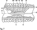
器具10の動作は、図7を参照すると最もよく理解することができる。血管形成バルーン14、ベース部材26およびブレード・セグメント28a、28b、28cを含む器具10を有するカテーテル42を、最初に患者12の血管44に挿入する。狭窄部46を治療するには、血管形成バルーン14が狭窄部46を通って配置されるまで、カテーテル42を血管44内で前進させる。図示のように、ガイドワイヤ48を使用して、カテーテル42を治療部位まで補助する機械的通路を確立することができる。適切に配置したら、バルーン14を徐々に膨脹させ、ブレード・セグメント28a、28b、28cが狭窄部46の表面50に接触するまで、バルーン14の外面、ベース部材26およびブレード・セグメント28a、28b、28cがバルーン軸線16から半径方向で外側に移動するようにする。
The operation of the
なお図7を参照すると、バルーン14を膨脹させると1つまたは複数のブレード・セグメント28a、28b、28cが狭窄部46の表面50に接触し、狭窄部46に切開部を切り込むことが理解される。バルーン14を引き続き膨脹させると、1つまたは複数のブレード・セグメント28a、28b、28cが狭窄部46に埋め込まれる。最終的に、バルーン14の外面および弾性ベース部材26が、狭窄部46の表面50と接触し、これと一致する。ブレード・セグメント28a、28b、28cが関節状で、偏っているので、ブレード・セグメント28a、28b、28cは、バルーン14およびベース部材26が狭窄部46の表面50に一致するのを妨げない。また、図示のように、ブレード・セグメント28a、28b、28c間の相対動作のため、ブレード・セグメント28a、28b、28cは、狭窄部46の表面50に一致する切線43(図4に図示)に沿って効果的な切刃を形成することができ、その結果、狭窄部46の表面の頂および谷に沿ってほぼ均一の深さのほぼ連続的切開部が生じる。
Referring still to FIG. 7, it can be seen that when the
切開後、所望に応じて、血管形成バルーン14をさらに膨脹させ、狭窄部46を拡張することができる。治療後、血管形成バルーン14をその後に収縮され、ブレード・セグメント28a、28b、28cを狭窄部46から引っ込める。収縮したら、所望に応じてバルーン14を再度膨脹させ、プロセスを反復することができる。狭窄部46の治療後、収縮したバルーン14は、別の狭窄部46を治療するために再配置するか、患者12から取り出すことができる。
After incision, the
本明細書で詳細に図示し、開示したような特定の器具および方法は、本明細書で前述した目的を達成し、利点を提供することが十分できるが、これは本発明の現在好ましい実施形態を単に例証するものであり、添付請求の範囲の記載を除き、本明細書で示した構造または設計の詳細を制限するものではないことが理解される。 Although certain instruments and methods as illustrated and disclosed in detail herein are sufficient to achieve the objectives previously described herein and provide advantages, this is a presently preferred embodiment of the present invention. It is understood that this is merely illustrative and is not intended to limit the details of construction or design set forth herein, except as set forth in the appended claims.
Claims (4)
前記バルーンの前記外面に装着され、前記バルーンと共に動作する間、前記バルーンの前記外面にほぼ適合する、弾性ベース部材と、An elastic base member mounted on the outer surface of the balloon and substantially conforming to the outer surface of the balloon while operating with the balloon;
複数のブレード・セグメントであり、複数のブレード・セグメントは前記ベース部材に取り付けられ、前記ブレード・セグメントの各々の部分は、少なくとも1つの他の前記ブレード・セグメントの部分と並置され、そこから軸線方向に偏って、前記バルーンが前記収縮構成から前記膨脹構成へと動作する間、前記ブレード・セグメント間の相対運動を可能にして、前記バルーンの前記外面が脈管構造の狭窄部と一致する間に前記複数のブレード・セグメントのうち少なくとも1つが狭窄部に埋め込まれる、複数のブレード・セグメントと、を有する装置。A plurality of blade segments, wherein the plurality of blade segments are attached to the base member, each portion of the blade segment being juxtaposed with at least one other portion of the blade segment and axially therefrom While the balloon moves from the deflated configuration to the inflated configuration, allowing relative movement between the blade segments, while the outer surface of the balloon is coincident with the constriction of the vasculature. A plurality of blade segments, wherein at least one of the plurality of blade segments is embedded in a constriction.
Applications Claiming Priority (2)
| Application Number | Priority Date | Filing Date | Title |
|---|---|---|---|
| US09/938,010 US6632231B2 (en) | 2001-08-23 | 2001-08-23 | Segmented balloon catheter blade |
| PCT/US2002/010732 WO2003018099A1 (en) | 2001-08-23 | 2002-04-04 | Segmented balloon catheter blade |
Publications (3)
| Publication Number | Publication Date |
|---|---|
| JP2005507683A JP2005507683A (en) | 2005-03-24 |
| JP2005507683A5 JP2005507683A5 (en) | 2005-12-22 |
| JP4170904B2 true JP4170904B2 (en) | 2008-10-22 |
Family
ID=25470724
Family Applications (1)
| Application Number | Title | Priority Date | Filing Date |
|---|---|---|---|
| JP2003522612A Expired - Fee Related JP4170904B2 (en) | 2001-08-23 | 2002-04-04 | Split balloon, catheter, blade |
Country Status (7)
| Country | Link |
|---|---|
| US (3) | US6632231B2 (en) |
| EP (1) | EP1427470B1 (en) |
| JP (1) | JP4170904B2 (en) |
| AT (1) | ATE345832T1 (en) |
| CA (1) | CA2458366C (en) |
| DE (1) | DE60216294T2 (en) |
| WO (1) | WO2003018099A1 (en) |
Families Citing this family (123)
| Publication number | Priority date | Publication date | Assignee | Title |
|---|---|---|---|---|
| US7056294B2 (en) * | 2000-04-13 | 2006-06-06 | Ev3 Sunnyvale, Inc | Method and apparatus for accessing the left atrial appendage |
| WO2002007795A2 (en) * | 2000-07-24 | 2002-01-31 | Jeffrey Grayzel | Stiffened balloon catheter for dilatation and stenting |
| AU2002345328A1 (en) | 2001-06-27 | 2003-03-03 | Remon Medical Technologies Ltd. | Method and device for electrochemical formation of therapeutic species in vivo |
| US8061006B2 (en) * | 2001-07-26 | 2011-11-22 | Powderject Research Limited | Particle cassette, method and kit therefor |
| EP1415681A4 (en) * | 2001-08-08 | 2008-05-28 | Kaneka Corp | Expansion catheter |
| US6632231B2 (en) * | 2001-08-23 | 2003-10-14 | Scimed Life Systems, Inc. | Segmented balloon catheter blade |
| US7691119B2 (en) | 2001-11-09 | 2010-04-06 | Angioscore, Inc. | Balloon catheter with non-deployable stent |
| US20040111108A1 (en) | 2001-11-09 | 2004-06-10 | Farnan Robert C. | Balloon catheter with non-deployable stent |
| US6951566B2 (en) * | 2002-01-25 | 2005-10-04 | Scimed Life Systems, Inc. | Reciprocating cutting and dilating balloon |
| US7985234B2 (en) * | 2002-02-27 | 2011-07-26 | Boston Scientific Scimed, Inc. | Medical device |
| US7494497B2 (en) * | 2003-01-02 | 2009-02-24 | Boston Scientific Scimed, Inc. | Medical devices |
| US8080026B2 (en) | 2003-01-21 | 2011-12-20 | Angioscore, Inc. | Apparatus and methods for treating hardened vascular lesions |
| US6746463B1 (en) * | 2003-01-27 | 2004-06-08 | Scimed Life Systems, Inc | Device for percutaneous cutting and dilating a stenosis of the aortic valve |
| JP2004297166A (en) * | 2003-03-25 | 2004-10-21 | Murata Mfg Co Ltd | Temperature-compensated piezoelectric oscillator and electronic equipment using the same |
| US7131981B2 (en) * | 2003-03-25 | 2006-11-07 | Angiodynamics, Inc. | Device and method for converting a balloon catheter into a cutting balloon catheter |
| US7279002B2 (en) | 2003-04-25 | 2007-10-09 | Boston Scientific Scimed, Inc. | Cutting stent and balloon |
| US7632288B2 (en) | 2003-05-12 | 2009-12-15 | Boston Scientific Scimed, Inc. | Cutting balloon catheter with improved pushability |
| US7758604B2 (en) * | 2003-05-29 | 2010-07-20 | Boston Scientific Scimed, Inc. | Cutting balloon catheter with improved balloon configuration |
| US8876882B2 (en) * | 2003-10-10 | 2014-11-04 | Mark Gelido Barongan | Cutting stent |
| US7799043B2 (en) * | 2003-12-01 | 2010-09-21 | Boston Scientific Scimed, Inc. | Cutting balloon having sheathed incising elements |
| US8048093B2 (en) * | 2003-12-19 | 2011-11-01 | Boston Scientific Scimed, Inc. | Textured balloons |
| US7771447B2 (en) * | 2003-12-19 | 2010-08-10 | Boston Scientific Scimed, Inc. | Balloon refolding device |
| US7338463B2 (en) * | 2003-12-19 | 2008-03-04 | Boston Scientific Scimed, Inc. | Balloon blade sheath |
| US7413558B2 (en) * | 2003-12-19 | 2008-08-19 | Boston Scientific Scimed, Inc. | Elastically distensible folding member |
| US8043311B2 (en) * | 2003-12-22 | 2011-10-25 | Boston Scientific Scimed, Inc. | Medical device systems |
| US7270673B2 (en) * | 2003-12-31 | 2007-09-18 | Boston Scientific Scimed, Inc. | Microsurgical balloon with protective reinforcement |
| US7754047B2 (en) * | 2004-04-08 | 2010-07-13 | Boston Scientific Scimed, Inc. | Cutting balloon catheter and method for blade mounting |
| US7566319B2 (en) | 2004-04-21 | 2009-07-28 | Boston Scientific Scimed, Inc. | Traction balloon |
| US7070576B2 (en) * | 2004-04-30 | 2006-07-04 | Boston Scientific Scimed, Inc. | Directional cutting balloon |
| CN1984613B (en) * | 2004-05-19 | 2010-09-29 | 欣蒂生物技术股份公司 | Intravertebral widening device |
| US8043259B2 (en) * | 2004-05-24 | 2011-10-25 | Boston Scientific Scimed, Inc. | Medical device systems |
| US7976557B2 (en) * | 2004-06-23 | 2011-07-12 | Boston Scientific Scimed, Inc. | Cutting balloon and process |
| US7494612B2 (en) * | 2004-10-29 | 2009-02-24 | Boston Scientific Scimed, Inc. | Medical balloon folding method and tooling |
| US7291158B2 (en) * | 2004-11-12 | 2007-11-06 | Boston Scientific Scimed, Inc. | Cutting balloon catheter having a segmented blade |
| US8038691B2 (en) | 2004-11-12 | 2011-10-18 | Boston Scientific Scimed, Inc. | Cutting balloon catheter having flexible atherotomes |
| US8066726B2 (en) * | 2004-11-23 | 2011-11-29 | Boston Scientific Scimed, Inc. | Serpentine cutting blade for cutting balloon |
| US20060116700A1 (en) * | 2004-11-29 | 2006-06-01 | Crow Loren M | Aortic stenosis cutting balloon blade |
| US7658744B2 (en) * | 2004-12-03 | 2010-02-09 | Boston Scientific Scimed, Inc. | Multiple balloon catheter |
| US7879053B2 (en) * | 2004-12-20 | 2011-02-01 | Boston Scientific Scimed, Inc. | Balloon with stepped sections and implements |
| US20060178685A1 (en) * | 2004-12-30 | 2006-08-10 | Cook Incorporated | Balloon expandable plaque cutting device |
| DE602005010906D1 (en) * | 2004-12-30 | 2008-12-18 | Cook Inc | CATHETER ASSEMBLY WITH PLAQUE CUTTING BALLOON |
| US20060173487A1 (en) * | 2005-01-05 | 2006-08-03 | Cook Incorporated | Angioplasty cutting device and method for treating a stenotic lesion in a body vessel |
| US20060184191A1 (en) * | 2005-02-11 | 2006-08-17 | Boston Scientific Scimed, Inc. | Cutting balloon catheter having increased flexibility regions |
| US20060247674A1 (en) * | 2005-04-29 | 2006-11-02 | Roman Ricardo D | String cutting balloon |
| US10076641B2 (en) | 2005-05-11 | 2018-09-18 | The Spectranetics Corporation | Methods and systems for delivering substances into luminal walls |
| US7771446B2 (en) * | 2005-09-21 | 2010-08-10 | Rutter Michael John | Balloon dilator |
| US20070066961A1 (en) * | 2005-09-21 | 2007-03-22 | Rutter Michael J | Airway balloon dilator |
| US7708753B2 (en) | 2005-09-27 | 2010-05-04 | Cook Incorporated | Balloon catheter with extendable dilation wire |
| US8123770B2 (en) * | 2005-11-01 | 2012-02-28 | Cook Medical Technologies Llc | Angioplasty cutting device and method for treating a stenotic lesion in a body vessel |
| WO2007075986A2 (en) * | 2005-12-20 | 2007-07-05 | Medical Components, Inc. | Cutting balloon catheter assembly |
| US8840660B2 (en) | 2006-01-05 | 2014-09-23 | Boston Scientific Scimed, Inc. | Bioerodible endoprostheses and methods of making the same |
| US8089029B2 (en) | 2006-02-01 | 2012-01-03 | Boston Scientific Scimed, Inc. | Bioabsorbable metal medical device and method of manufacture |
| US20080077164A1 (en) * | 2006-02-24 | 2008-03-27 | National University Of Ireland, Galway | Minimally Invasive Intravascular Treatment Device |
| US7691116B2 (en) * | 2006-03-09 | 2010-04-06 | Boston Scientific Scimed, Inc. | Cutting blade for medical devices |
| US8048150B2 (en) | 2006-04-12 | 2011-11-01 | Boston Scientific Scimed, Inc. | Endoprosthesis having a fiber meshwork disposed thereon |
| US8052743B2 (en) * | 2006-08-02 | 2011-11-08 | Boston Scientific Scimed, Inc. | Endoprosthesis with three-dimensional disintegration control |
| CA2663220A1 (en) | 2006-09-15 | 2008-03-20 | Boston Scientific Limited | Medical devices and methods of making the same |
| CA2663303A1 (en) * | 2006-09-15 | 2008-03-20 | Boston Scientific Limited | Endoprosthesis with adjustable surface features |
| WO2008034048A2 (en) | 2006-09-15 | 2008-03-20 | Boston Scientific Limited | Bioerodible endoprosthesis with biostable inorganic layers |
| WO2008034066A1 (en) | 2006-09-15 | 2008-03-20 | Boston Scientific Limited | Bioerodible endoprostheses and methods of making the same |
| CA2663250A1 (en) | 2006-09-15 | 2008-03-20 | Boston Scientific Limited | Bioerodible endoprostheses and methods of making the same |
| ATE530210T1 (en) * | 2006-09-18 | 2011-11-15 | Boston Scient Ltd | ENDOPROSTHESES |
| US8002821B2 (en) | 2006-09-18 | 2011-08-23 | Boston Scientific Scimed, Inc. | Bioerodible metallic ENDOPROSTHESES |
| US20080097577A1 (en) * | 2006-10-20 | 2008-04-24 | Boston Scientific Scimed, Inc. | Medical device hydrogen surface treatment by electrochemical reduction |
| EP2125065B1 (en) | 2006-12-28 | 2010-11-17 | Boston Scientific Limited | Bioerodible endoprostheses and methods of making same |
| US20080228139A1 (en) * | 2007-02-06 | 2008-09-18 | Cook Incorporated | Angioplasty Balloon With Concealed Wires |
| US8323307B2 (en) | 2007-02-13 | 2012-12-04 | Cook Medical Technologies Llc | Balloon catheter with dilating elements |
| US7842056B2 (en) * | 2007-05-18 | 2010-11-30 | Boston Scientific Scimed, Inc. | Cutting member for bifurcation catheter assembly |
| US20080300610A1 (en) * | 2007-05-31 | 2008-12-04 | Cook Incorporated | Device for treating hardened lesions and method of use thereof |
| US8929988B2 (en) | 2007-07-11 | 2015-01-06 | Apollo Endosurgery, Inc. | Methods and systems for submucosal implantation of a device for diagnosis and treatment of a body |
| US8317771B2 (en) | 2007-07-11 | 2012-11-27 | Apollo Endosurgery, Inc. | Methods and systems for performing submucosal medical procedures |
| US8066689B2 (en) | 2007-07-11 | 2011-11-29 | Apollo Endosurgery, Inc. | Methods and systems for submucosal implantation of a device for diagnosis and treatment with a therapeutic agent |
| US8128592B2 (en) | 2007-07-11 | 2012-03-06 | Apollo Endosurgery, Inc. | Methods and systems for performing submucosal medical procedures |
| US8052745B2 (en) | 2007-09-13 | 2011-11-08 | Boston Scientific Scimed, Inc. | Endoprosthesis |
| US10123803B2 (en) * | 2007-10-17 | 2018-11-13 | Covidien Lp | Methods of managing neurovascular obstructions |
| US8192675B2 (en) | 2008-03-13 | 2012-06-05 | Cook Medical Technologies Llc | Cutting balloon with connector and dilation element |
| WO2009117158A2 (en) | 2008-03-21 | 2009-09-24 | Innovasc Llc | Device and method for opening blood vessels by pre-angioplasty serration and dilatation of aetherosclerotic plaque |
| US9480826B2 (en) | 2008-03-21 | 2016-11-01 | Cagent Vascular, Llc | Intravascular device |
| US11219750B2 (en) | 2008-03-21 | 2022-01-11 | Cagent Vascular, Inc. | System and method for plaque serration |
| US7998192B2 (en) | 2008-05-09 | 2011-08-16 | Boston Scientific Scimed, Inc. | Endoprostheses |
| US20090287045A1 (en) | 2008-05-15 | 2009-11-19 | Vladimir Mitelberg | Access Systems and Methods of Intra-Abdominal Surgery |
| US8236046B2 (en) | 2008-06-10 | 2012-08-07 | Boston Scientific Scimed, Inc. | Bioerodible endoprosthesis |
| US20100010521A1 (en) * | 2008-07-10 | 2010-01-14 | Cook Incorporated | Cutting balloon with movable member |
| US7985252B2 (en) | 2008-07-30 | 2011-07-26 | Boston Scientific Scimed, Inc. | Bioerodible endoprosthesis |
| US8382824B2 (en) | 2008-10-03 | 2013-02-26 | Boston Scientific Scimed, Inc. | Medical implant having NANO-crystal grains with barrier layers of metal nitrides or fluorides |
| EP2370138B1 (en) * | 2008-11-25 | 2020-12-30 | Edwards Lifesciences Corporation | Apparatus for in situ expansion of prosthetic device |
| US20100179517A1 (en) * | 2009-01-09 | 2010-07-15 | Jiro Takashima | Catheter |
| EP2403546A2 (en) | 2009-03-02 | 2012-01-11 | Boston Scientific Scimed, Inc. | Self-buffering medical implants |
| US20100286593A1 (en) * | 2009-05-11 | 2010-11-11 | Hotspur Technologies, Inc. | Balloon catheter with cutting features and methods for use |
| US8348987B2 (en) * | 2009-12-22 | 2013-01-08 | Cook Medical Technologies Llc | Balloon with scoring member |
| WO2011119573A1 (en) | 2010-03-23 | 2011-09-29 | Boston Scientific Scimed, Inc. | Surface treated bioerodible metal endoprostheses |
| EP2380604A1 (en) | 2010-04-19 | 2011-10-26 | InnoRa Gmbh | Improved coating formulations for scoring or cutting balloon catheters |
| US8764705B2 (en) | 2010-05-07 | 2014-07-01 | Cook Medical Technologies Llc | Balloon with integral segmented dilation elements |
| US8632559B2 (en) | 2010-09-21 | 2014-01-21 | Angioscore, Inc. | Method and system for treating valve stenosis |
| US8685049B2 (en) | 2010-11-18 | 2014-04-01 | Rex Medical L.P. | Cutting wire assembly for use with a catheter |
| US9282991B2 (en) | 2010-10-06 | 2016-03-15 | Rex Medical, L.P. | Cutting wire assembly with coating for use with a catheter |
| US8685050B2 (en) | 2010-10-06 | 2014-04-01 | Rex Medical L.P. | Cutting wire assembly for use with a catheter |
| GB2485769B (en) * | 2010-11-22 | 2012-12-05 | Cook Medical Technologies Llc | Scoring balloon and method of making same |
| US8702736B2 (en) | 2010-11-22 | 2014-04-22 | Rex Medical L.P. | Cutting wire assembly for use with a catheter |
| US8491615B2 (en) | 2010-12-29 | 2013-07-23 | Boston Scientific Scimed, Inc. | Cutting balloon catheter |
| GB2487400B (en) * | 2011-01-20 | 2013-07-10 | Cook Medical Technologies Llc | Scoring balloon with offset scoring elements |
| US9226768B2 (en) | 2011-07-15 | 2016-01-05 | Boston Scientific Scimed, Inc. | Cutting balloon catheter with flexible cutting blades |
| US9763691B2 (en) | 2011-08-11 | 2017-09-19 | Boston Scientific Scimed, Inc. | Expandable scaffold with cutting elements mounted thereto |
| US9364255B2 (en) | 2011-11-09 | 2016-06-14 | Boston Scientific Scimed, Inc. | Medical cutting devices and methods of use |
| US8827953B2 (en) | 2013-01-15 | 2014-09-09 | Krishna Rocha-Singh | Apparatus and method for delivering intraluminal therapy |
| WO2014169266A1 (en) * | 2013-04-12 | 2014-10-16 | Yu Yongyi Alan | Systems and methods for restoring blood flow to a vessel |
| US10117668B2 (en) | 2013-10-08 | 2018-11-06 | The Spectranetics Corporation | Balloon catheter with non-deployable stent having improved stability |
| CA2927436C (en) | 2013-10-15 | 2022-04-26 | Stryker Corporation | Device for creating a void space in living tissue, the device including a handle with a control knob that can be set regardless of the orientation of the handle |
| US10286190B2 (en) | 2013-12-11 | 2019-05-14 | Cook Medical Technologies Llc | Balloon catheter with dynamic vessel engaging member |
| CN104906682A (en) | 2014-01-24 | 2015-09-16 | 史蒂文·沙勒布瓦 | Articulating balloon catheter and method for using the same |
| US10463842B2 (en) | 2014-06-04 | 2019-11-05 | Cagent Vascular, Llc | Cage for medical balloon |
| EP3215212B1 (en) | 2014-11-03 | 2020-07-29 | Cagent Vascular, LLC | Serration balloon |
| EP3226783B1 (en) | 2014-12-03 | 2024-01-10 | PAVmed Inc. | Systems for percutaneous division of fibrous structures |
| US10603069B2 (en) * | 2015-01-13 | 2020-03-31 | John P. Pigott | Intravascular catheter balloon device having a tool for atherectomy or an incising portion for atheromatous plaque scoring |
| US10182841B1 (en) * | 2015-06-16 | 2019-01-22 | C.R. Bard, Inc. | Medical balloon with enhanced focused force control |
| EP3799919A1 (en) | 2015-09-17 | 2021-04-07 | Cagent Vascular, LLC | Wedge dissectors for a medical ballon |
| WO2018094077A1 (en) | 2016-11-16 | 2018-05-24 | Cagent Vascular, Llc | Systems and methods of depositing drug into tissue through serrations |
| US11154320B2 (en) | 2018-04-09 | 2021-10-26 | Boston Scientific Scimed, Inc. | Cutting balloon basket |
| CA3105746A1 (en) | 2018-07-25 | 2020-01-30 | Cagent Vascular, Llc | Medical balloon catheters with enhanced pushability |
| EP3958752A2 (en) | 2019-04-24 | 2022-03-02 | Stryker Corporation | Systems for off-axis augmentation of a vertebral body |
| US11812987B2 (en) | 2019-11-27 | 2023-11-14 | Boston Scientific Scimed, Inc. | Cutting balloon catheter |
| EP3928824B1 (en) * | 2020-04-30 | 2023-11-29 | Brosmed Medical Co., Ltd. | Cutting apparatus and cutting balloon |
| WO2022038468A1 (en) * | 2020-08-19 | 2022-02-24 | Baylis Medical Company Inc. | Medical device and method for accessing the pericardial space |
Family Cites Families (84)
| Publication number | Priority date | Publication date | Assignee | Title |
|---|---|---|---|---|
| US2730101A (en) | 1954-02-23 | 1956-01-10 | Roy D Hoffman | Teat bistoury with expansible cutter knives |
| US3512519A (en) | 1967-10-26 | 1970-05-19 | Robert M Hall | Anatomical biopsy sampler |
| US3605721A (en) | 1969-11-03 | 1971-09-20 | Ismet Hallac | Biopsy needle |
| US4273128A (en) | 1980-01-14 | 1981-06-16 | Lary Banning G | Coronary cutting and dilating instrument |
| US4402307A (en) | 1980-10-31 | 1983-09-06 | Datascope Corp. | Balloon catheter with rotatable energy storing support member |
| US4572186A (en) * | 1983-12-07 | 1986-02-25 | Cordis Corporation | Vessel dilation |
| US4589412A (en) * | 1984-01-03 | 1986-05-20 | Intravascular Surgical Instruments, Inc. | Method and apparatus for surgically removing remote deposits |
| US4631052A (en) * | 1984-01-03 | 1986-12-23 | Intravascular Surgical Instruments, Inc. | Method and apparatus for surgically removing remote deposits |
| US4781186A (en) * | 1984-05-30 | 1988-11-01 | Devices For Vascular Intervention, Inc. | Atherectomy device having a flexible housing |
| US4790813A (en) * | 1984-12-17 | 1988-12-13 | Intravascular Surgical Instruments, Inc. | Method and apparatus for surgically removing remote deposits |
| US5102390A (en) * | 1985-05-02 | 1992-04-07 | C. R. Bard, Inc. | Microdilatation probe and system for performing angioplasty in highly stenosed blood vessels |
| CH668192A5 (en) * | 1985-11-29 | 1988-12-15 | Schneider Medintag Ag | CATHETER FOR TREATING NARROW BODIES, FOR EXAMPLE IN A BLOOD VESSEL. |
| US4669469A (en) | 1986-02-28 | 1987-06-02 | Devices For Vascular Intervention | Single lumen atherectomy catheter device |
| US4696667A (en) * | 1986-03-20 | 1987-09-29 | Helmut Masch | Intravascular catheter and method |
| US4728319A (en) * | 1986-03-20 | 1988-03-01 | Helmut Masch | Intravascular catheter |
| US4765332A (en) * | 1986-07-14 | 1988-08-23 | Medinnovations, Inc. | Pullback atherectomy catheter system |
| US4748982A (en) * | 1987-01-06 | 1988-06-07 | Advanced Cardiovascular Systems, Inc. | Reinforced balloon dilatation catheter with slitted exchange sleeve and method |
| US4867157A (en) * | 1987-08-13 | 1989-09-19 | Baxter Travenol Laboratories, Inc. | Surgical cutting instrument |
| US5047040A (en) * | 1987-11-05 | 1991-09-10 | Devices For Vascular Intervention, Inc. | Atherectomy device and method |
| US4887613A (en) * | 1987-11-23 | 1989-12-19 | Interventional Technologies Inc. | Cutter for atherectomy device |
| US5053044A (en) * | 1988-01-11 | 1991-10-01 | Devices For Vascular Intervention, Inc. | Catheter and method for making intravascular incisions |
| US4886061A (en) * | 1988-02-09 | 1989-12-12 | Medinnovations, Inc. | Expandable pullback atherectomy catheter system |
| US4909781A (en) * | 1988-04-08 | 1990-03-20 | Husted Royce Hill | Catheter with flexible cutter |
| US4896669A (en) | 1988-08-31 | 1990-01-30 | Meadox Medicals, Inc. | Dilatation catheter |
| DE3830704A1 (en) * | 1988-09-09 | 1990-03-22 | Falah Redha | MEDICAL INSTRUMENT |
| US4966604A (en) | 1989-01-23 | 1990-10-30 | Interventional Technologies Inc. | Expandable atherectomy cutter with flexibly bowed blades |
| US4950277A (en) * | 1989-01-23 | 1990-08-21 | Interventional Technologies, Inc. | Atherectomy cutting device with eccentric wire and method |
| US4986807A (en) * | 1989-01-23 | 1991-01-22 | Interventional Technologies, Inc. | Atherectomy cutter with radially projecting blade |
| US5156610A (en) * | 1989-08-18 | 1992-10-20 | Evi Corporation | Catheter atherotome |
| US5571169A (en) * | 1993-06-07 | 1996-11-05 | Endovascular Instruments, Inc. | Anti-stenotic method and product for occluded and partially occluded arteries |
| US5180368A (en) * | 1989-09-08 | 1993-01-19 | Advanced Cardiovascular Systems, Inc. | Rapidly exchangeable and expandable cage catheter for repairing damaged blood vessels |
| US5226909A (en) * | 1989-09-12 | 1993-07-13 | Devices For Vascular Intervention, Inc. | Atherectomy device having helical blade and blade guide |
| US5009659A (en) * | 1989-10-30 | 1991-04-23 | Schneider (Usa) Inc. | Fiber tip atherectomy catheter |
| US5030201A (en) * | 1989-11-24 | 1991-07-09 | Aubrey Palestrant | Expandable atherectomy catheter device |
| US5178625A (en) * | 1989-12-07 | 1993-01-12 | Evi Corporation | Catheter atherotome |
| US5074871A (en) * | 1989-12-07 | 1991-12-24 | Evi Corporation | Catheter atherotome |
| US5074841A (en) * | 1990-01-30 | 1991-12-24 | Microcision, Inc. | Atherectomy device with helical cutter |
| US5181920A (en) | 1990-06-08 | 1993-01-26 | Devices For Vascular Intervention, Inc. | Atherectomy device with angioplasty balloon and method |
| US5196024A (en) * | 1990-07-03 | 1993-03-23 | Cedars-Sinai Medical Center | Balloon catheter with cutting edge |
| US5320634A (en) * | 1990-07-03 | 1994-06-14 | Interventional Technologies, Inc. | Balloon catheter with seated cutting edges |
| US5192291A (en) * | 1992-01-13 | 1993-03-09 | Interventional Technologies, Inc. | Rotationally expandable atherectomy cutter assembly |
| US5224945A (en) * | 1992-01-13 | 1993-07-06 | Interventional Technologies, Inc. | Compressible/expandable atherectomy cutter |
| US5250059A (en) * | 1992-01-22 | 1993-10-05 | Devices For Vascular Intervention, Inc. | Atherectomy catheter having flexible nose cone |
| US5176693A (en) * | 1992-05-11 | 1993-01-05 | Interventional Technologies, Inc. | Balloon expandable atherectomy cutter |
| CH685738A5 (en) * | 1993-03-25 | 1995-09-29 | Ferromec Sa | Medical instrument for removing deposits formed on the inner walls of the arteries or veins. |
| US5372601A (en) * | 1993-03-30 | 1994-12-13 | Lary; Banning G. | Longitudinal reciprocating incisor |
| CA2118886C (en) * | 1993-05-07 | 1998-12-08 | Dennis Vigil | Method and apparatus for dilatation of a stenotic vessel |
| US5417703A (en) * | 1993-07-13 | 1995-05-23 | Scimed Life Systems, Inc. | Thrombectomy devices and methods of using same |
| US5441510A (en) * | 1993-09-01 | 1995-08-15 | Technology Development Center | Bi-axial cutter apparatus for catheter |
| US5961765A (en) * | 1994-09-20 | 1999-10-05 | Schneider (Europe) A. G. | Method of making a catheter |
| US5507760A (en) * | 1993-11-09 | 1996-04-16 | Devices For Vascular Intervention, Inc. | Cutter device |
| US5507761A (en) * | 1994-10-11 | 1996-04-16 | Duer; Edward Y. | Embolic cutting catheter |
| US5643296A (en) * | 1994-12-16 | 1997-07-01 | Devices For Vasclar Intervention | Intravascular catheter with guiding structure |
| US5728123A (en) * | 1995-04-26 | 1998-03-17 | Lemelson; Jerome H. | Balloon actuated catheter |
| US5833657A (en) * | 1995-05-30 | 1998-11-10 | Ethicon, Inc. | Single-walled balloon catheter with non-linear compliance characteristic |
| US5746716A (en) * | 1995-07-10 | 1998-05-05 | Interventional Technologies Inc. | Catheter for injecting fluid medication into an arterial wall |
| US5766203A (en) | 1995-07-20 | 1998-06-16 | Intelliwire, Inc. | Sheath with expandable distal extremity and balloon catheters and stents for use therewith and method |
| US5556405A (en) * | 1995-10-13 | 1996-09-17 | Interventional Technologies Inc. | Universal dilator with reciprocal incisor |
| US5792158A (en) * | 1995-11-15 | 1998-08-11 | Lary; Banning Gray | University dilator with expandable incisor |
| CA2249425A1 (en) * | 1996-04-26 | 1997-11-06 | Medtronic, Inc. | Intravascular balloon occlusion device and method for using the same |
| US6544276B1 (en) * | 1996-05-20 | 2003-04-08 | Medtronic Ave. Inc. | Exchange method for emboli containment |
| CA2209366C (en) * | 1996-09-13 | 2004-11-02 | Interventional Technologies, Inc. | Incisor-dilator with tapered balloon |
| US5797935A (en) | 1996-09-26 | 1998-08-25 | Interventional Technologies Inc. | Balloon activated forced concentrators for incising stenotic segments |
| US5713913A (en) * | 1996-11-12 | 1998-02-03 | Interventional Technologies Inc. | Device and method for transecting a coronary artery |
| JP2001512334A (en) * | 1997-02-12 | 2001-08-21 | プロリフィックス メディカル,インコーポレイテッド | Equipment for removing material from stents |
| US6217549B1 (en) * | 1997-02-28 | 2001-04-17 | Lumend, Inc. | Methods and apparatus for treating vascular occlusions |
| US6355016B1 (en) * | 1997-03-06 | 2002-03-12 | Medtronic Percusurge, Inc. | Catheter core wire |
| EP0884063B1 (en) * | 1997-06-10 | 2004-04-28 | Schneider ( Europe) GmbH | Catheter system |
| US6156046A (en) | 1997-11-07 | 2000-12-05 | Prolifix Medical, Inc. | Methods and systems for treating obstructions in a body lumen |
| US6398798B2 (en) * | 1998-02-28 | 2002-06-04 | Lumend, Inc. | Catheter system for treating a vascular occlusion |
| US6306151B1 (en) * | 1998-03-31 | 2001-10-23 | Interventional Technologies Inc. | Balloon with reciprocating stent incisor |
| US6036708A (en) * | 1998-08-13 | 2000-03-14 | Advanced Cardiovascular Systems, Inc. | Cutting stent with flexible tissue extractor |
| US6165140A (en) * | 1998-12-28 | 2000-12-26 | Micrus Corporation | Composite guidewire |
| ES2220026T3 (en) * | 1999-03-29 | 2004-12-01 | William Cook Europe Aps | GUIDE-THREADS. |
| US6447525B2 (en) | 1999-08-19 | 2002-09-10 | Fox Hollow Technologies, Inc. | Apparatus and methods for removing material from a body lumen |
| US6533754B1 (en) * | 1999-11-26 | 2003-03-18 | Terumo Kabushiki Kaisha | Catheter |
| US6468227B2 (en) | 2000-03-17 | 2002-10-22 | Zimmon Science Corporation | Device for performing a medical procedure |
| WO2002007795A2 (en) * | 2000-07-24 | 2002-01-31 | Jeffrey Grayzel | Stiffened balloon catheter for dilatation and stenting |
| US6416523B1 (en) * | 2000-10-03 | 2002-07-09 | Scimed Life Systems, Inc. | Method and apparatus for creating channels through vascular total occlusions |
| US6500186B2 (en) * | 2001-04-17 | 2002-12-31 | Scimed Life Systems, Inc. | In-stent ablative tool |
| US6425882B1 (en) * | 2001-05-01 | 2002-07-30 | Interventional Technologies Inc. | Folding spring for a catheter balloon |
| US6562062B2 (en) | 2001-08-10 | 2003-05-13 | Scimed Life Systems, Inc. | Balloon anchoring system |
| US6632231B2 (en) * | 2001-08-23 | 2003-10-14 | Scimed Life Systems, Inc. | Segmented balloon catheter blade |
| US6951566B2 (en) | 2002-01-25 | 2005-10-04 | Scimed Life Systems, Inc. | Reciprocating cutting and dilating balloon |
-
2001
- 2001-08-23 US US09/938,010 patent/US6632231B2/en not_active Expired - Lifetime
-
2002
- 2002-04-04 AT AT02796180T patent/ATE345832T1/en not_active IP Right Cessation
- 2002-04-04 JP JP2003522612A patent/JP4170904B2/en not_active Expired - Fee Related
- 2002-04-04 WO PCT/US2002/010732 patent/WO2003018099A1/en active IP Right Grant
- 2002-04-04 DE DE60216294T patent/DE60216294T2/en not_active Expired - Lifetime
- 2002-04-04 EP EP02796180A patent/EP1427470B1/en not_active Expired - Lifetime
- 2002-04-04 CA CA002458366A patent/CA2458366C/en not_active Expired - Fee Related
-
2003
- 2003-08-05 US US10/634,298 patent/US7011670B2/en not_active Expired - Lifetime
- 2003-10-10 US US10/683,893 patent/US7172609B2/en not_active Expired - Fee Related
Also Published As
| Publication number | Publication date |
|---|---|
| WO2003018099A1 (en) | 2003-03-06 |
| US20040098018A1 (en) | 2004-05-20 |
| CA2458366C (en) | 2009-12-15 |
| DE60216294T2 (en) | 2007-06-14 |
| US6632231B2 (en) | 2003-10-14 |
| US20040127920A1 (en) | 2004-07-01 |
| EP1427470B1 (en) | 2006-11-22 |
| EP1427470A4 (en) | 2004-11-03 |
| JP2005507683A (en) | 2005-03-24 |
| US20030040770A1 (en) | 2003-02-27 |
| US7172609B2 (en) | 2007-02-06 |
| US7011670B2 (en) | 2006-03-14 |
| EP1427470A1 (en) | 2004-06-16 |
| ATE345832T1 (en) | 2006-12-15 |
| CA2458366A1 (en) | 2003-03-06 |
| DE60216294D1 (en) | 2007-01-04 |
Similar Documents
| Publication | Publication Date | Title |
|---|---|---|
| JP4170904B2 (en) | Split balloon, catheter, blade | |
| US5792158A (en) | University dilator with expandable incisor | |
| US5697944A (en) | Universal dilator with expandable incisor | |
| US6951566B2 (en) | Reciprocating cutting and dilating balloon | |
| US5797935A (en) | Balloon activated forced concentrators for incising stenotic segments | |
| US8882790B2 (en) | Drug eluting sculpting balloon | |
| EP0565796B1 (en) | Stenosis dilatation device | |
| JP3359543B2 (en) | A device for perforating perfusion channels from blood vessels inside the patient's myocardium | |
| US5713913A (en) | Device and method for transecting a coronary artery | |
| JPH07409A (en) | Device and method for incising arteriostenosis part | |
| JP4851941B2 (en) | Instrument for refolding the balloon | |
| JPH08224249A (en) | Device to cut and expand constrixted are in blood vessel of patient,and its method | |
| JP2006515789A (en) | Device for percutaneously cutting and expanding aortic stenosis | |
| US20090281564A1 (en) | Pre-Clot Vessel Dilator | |
| US11576698B2 (en) | Intravascular catheter device for improved angioplasty | |
| JP2006087554A (en) | Expanding catheter |
Legal Events
| Date | Code | Title | Description |
|---|---|---|---|
| A521 | Request for written amendment filed |
Free format text: JAPANESE INTERMEDIATE CODE: A523 Effective date: 20050404 |
|
| A621 | Written request for application examination |
Free format text: JAPANESE INTERMEDIATE CODE: A621 Effective date: 20050404 |
|
| RD03 | Notification of appointment of power of attorney |
Free format text: JAPANESE INTERMEDIATE CODE: A7423 Effective date: 20060427 |
|
| RD04 | Notification of resignation of power of attorney |
Free format text: JAPANESE INTERMEDIATE CODE: A7424 Effective date: 20060427 |
|
| TRDD | Decision of grant or rejection written | ||
| A01 | Written decision to grant a patent or to grant a registration (utility model) |
Free format text: JAPANESE INTERMEDIATE CODE: A01 Effective date: 20080708 |
|
| A01 | Written decision to grant a patent or to grant a registration (utility model) |
Free format text: JAPANESE INTERMEDIATE CODE: A01 |
|
| A61 | First payment of annual fees (during grant procedure) |
Free format text: JAPANESE INTERMEDIATE CODE: A61 Effective date: 20080807 |
|
| FPAY | Renewal fee payment (event date is renewal date of database) |
Free format text: PAYMENT UNTIL: 20110815 Year of fee payment: 3 |
|
| R150 | Certificate of patent or registration of utility model |
Ref document number: 4170904 Country of ref document: JP Free format text: JAPANESE INTERMEDIATE CODE: R150 Free format text: JAPANESE INTERMEDIATE CODE: R150 |
|
| FPAY | Renewal fee payment (event date is renewal date of database) |
Free format text: PAYMENT UNTIL: 20110815 Year of fee payment: 3 |
|
| FPAY | Renewal fee payment (event date is renewal date of database) |
Free format text: PAYMENT UNTIL: 20120815 Year of fee payment: 4 |
|
| R250 | Receipt of annual fees |
Free format text: JAPANESE INTERMEDIATE CODE: R250 |
|
| FPAY | Renewal fee payment (event date is renewal date of database) |
Free format text: PAYMENT UNTIL: 20130815 Year of fee payment: 5 |
|
| R250 | Receipt of annual fees |
Free format text: JAPANESE INTERMEDIATE CODE: R250 |
|
| R250 | Receipt of annual fees |
Free format text: JAPANESE INTERMEDIATE CODE: R250 |
|
| R250 | Receipt of annual fees |
Free format text: JAPANESE INTERMEDIATE CODE: R250 |
|
| R250 | Receipt of annual fees |
Free format text: JAPANESE INTERMEDIATE CODE: R250 |
|
| R250 | Receipt of annual fees |
Free format text: JAPANESE INTERMEDIATE CODE: R250 |
|
| R250 | Receipt of annual fees |
Free format text: JAPANESE INTERMEDIATE CODE: R250 |
|
| R250 | Receipt of annual fees |
Free format text: JAPANESE INTERMEDIATE CODE: R250 |
|
| R250 | Receipt of annual fees |
Free format text: JAPANESE INTERMEDIATE CODE: R250 |
|
| LAPS | Cancellation because of no payment of annual fees |