EP0526822B1 - Procédé d'intervention à distance dans un puits d'un site de stockage profond de déchets nucléaires - Google Patents
Procédé d'intervention à distance dans un puits d'un site de stockage profond de déchets nucléaires Download PDFInfo
- Publication number
- EP0526822B1 EP0526822B1 EP92112852A EP92112852A EP0526822B1 EP 0526822 B1 EP0526822 B1 EP 0526822B1 EP 92112852 A EP92112852 A EP 92112852A EP 92112852 A EP92112852 A EP 92112852A EP 0526822 B1 EP0526822 B1 EP 0526822B1
- Authority
- EP
- European Patent Office
- Prior art keywords
- line
- carriage
- shaft
- gallery
- elevator
- Prior art date
- Legal status (The legal status is an assumption and is not a legal conclusion. Google has not performed a legal analysis and makes no representation as to the accuracy of the status listed.)
- Expired - Lifetime
Links
- 238000000034 method Methods 0.000 title claims abstract description 12
- 239000002699 waste material Substances 0.000 title description 2
- 239000002901 radioactive waste Substances 0.000 claims abstract description 7
- 230000002285 radioactive effect Effects 0.000 claims description 3
- 238000007599 discharging Methods 0.000 claims description 2
- 230000005540 biological transmission Effects 0.000 description 6
- 230000000694 effects Effects 0.000 description 2
- 238000012544 monitoring process Methods 0.000 description 2
- 230000005865 ionizing radiation Effects 0.000 description 1
- 239000000463 material Substances 0.000 description 1
- 238000005259 measurement Methods 0.000 description 1
- 239000011241 protective layer Substances 0.000 description 1
- 230000005855 radiation Effects 0.000 description 1
Images

Classifications
-
- H—ELECTRICITY
- H04—ELECTRIC COMMUNICATION TECHNIQUE
- H04B—TRANSMISSION
- H04B3/00—Line transmission systems
- H04B3/52—Systems for transmission between fixed stations via waveguides
-
- B—PERFORMING OPERATIONS; TRANSPORTING
- B61—RAILWAYS
- B61L—GUIDING RAILWAY TRAFFIC; ENSURING THE SAFETY OF RAILWAY TRAFFIC
- B61L3/00—Devices along the route for controlling devices on the vehicle or train, e.g. to release brake or to operate a warning signal
- B61L3/16—Continuous control along the route
- B61L3/22—Continuous control along the route using magnetic or electrostatic induction; using electromagnetic radiation
- B61L3/227—Continuous control along the route using magnetic or electrostatic induction; using electromagnetic radiation using electromagnetic radiation
-
- H—ELECTRICITY
- H01—ELECTRIC ELEMENTS
- H01Q—ANTENNAS, i.e. RADIO AERIALS
- H01Q1/00—Details of, or arrangements associated with, antennas
- H01Q1/27—Adaptation for use in or on movable bodies
- H01Q1/32—Adaptation for use in or on road or rail vehicles
- H01Q1/3208—Adaptation for use in or on road or rail vehicles characterised by the application wherein the antenna is used
- H01Q1/3233—Adaptation for use in or on road or rail vehicles characterised by the application wherein the antenna is used particular used as part of a sensor or in a security system, e.g. for automotive radar, navigation systems
-
- Y—GENERAL TAGGING OF NEW TECHNOLOGICAL DEVELOPMENTS; GENERAL TAGGING OF CROSS-SECTIONAL TECHNOLOGIES SPANNING OVER SEVERAL SECTIONS OF THE IPC; TECHNICAL SUBJECTS COVERED BY FORMER USPC CROSS-REFERENCE ART COLLECTIONS [XRACs] AND DIGESTS
- Y10—TECHNICAL SUBJECTS COVERED BY FORMER USPC
- Y10S—TECHNICAL SUBJECTS COVERED BY FORMER USPC CROSS-REFERENCE ART COLLECTIONS [XRACs] AND DIGESTS
- Y10S414/00—Material or article handling
- Y10S414/122—Remote control handlers
Definitions
- the present invention relates to a method of intervention in an underground gallery connected to the surface by a well provided with a freight elevator for deep storage of radioactive waste.
- French patent 2 608 119 describes a device for transmitting information and / or instructions with high bandwidth and / or for locating between a mobile element and a control station for this element, comprising a hollow tube parallel to the path followed by the mobile element, forming a waveguide, one emissive face of which is pierced with a network of openings for the passage of electromagnetic microwave radiation, the mobile element being provided with at least one transmitting antenna and / or for receiving microwave waves arranged opposite the face of the tube pierced with a network of openings, the hollow tube being connected to at least one member for supplying microwave waves and to one member for receiving microwave waves coming from him.
- Such a device allows the exchange of broadband analog and / or digital information at high speed, such as on the one hand telephone and / or video signals and / or on the other hand telemetry signals and / or remote controls and also allows position and / or speed measurements of the mobile element moving near the tube forming a microwave waveguide, which will be called waveguide below.
- the present invention relates to a method of intervention in a well and / or an underground gallery, in particular for the storage of radioactive waste using such waveguides. as transmission and remote control devices.
- Figure 1 is a schematic view of a site equipped according to the method according to the invention.
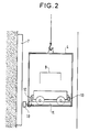
- Figure 2 is a schematic view showing more particularly the freight elevator.
- An underground intervention site in particular intended for the deep storage of radioactive waste comprises a well 2 connecting the surface 1 to a network of galleries 3 and equipped with a freight elevator 4.
- control station 5 Near the entrance to the well 2 is installed a control station 5.
- This control station includes a wave generator microwave and a signal receiving cabinet. The latter is connected to one or more television screens arranged on a control panel opposite the supervisor's station.
- the control station 5 is connected by a coaxial cable to a first line 6 of waveguide connecting this station 5 to the inlet of the well 2.
- the well 2 is equipped with a second line 7 of vertical waveguide and connected by a coaxial cable to the first line 6 by its upper end.
- a third line 8 of waveguides is installed in each gallery 3 and is connected by a coaxial cable to the second line 7 near the entrance to the gallery 3.
- the freight elevator 4 is equipped with an antenna 10 arranged opposite the second line 7. Thanks to this connection, the remote control and monitoring of the freight elevator 4 is carried out at the control station 5.
- the freight elevator 4 also includes a waveguide 11 arranged according to the example shown on its floor. This waveguide 11 is connected to the antenna 10 of the freight elevator.
- the presence of the two antennas 12, 13 makes it possible to keep the connection between the carriage and the control station continuous during the loading and unloading of the carriage 9 in and out of the freight elevator. During these discontinuous passages from the first line 6 to the guide 11 and from the latter to the third line 8, one of the antennas 12 or 13 always remains opposite the corresponding waveguides.
- the waveguides can be arranged on the floor, on the ceiling or laterally, the antennas 12, 13 of the carriage 9 being arranged accordingly.
- the intervention capacity can be increased, moreover, by multiplying the number of waveguides installed and operating in parallel.
- This intervention process is intended for the deep storage of radioactive waste.
- the carriage 9 is provided with means for transporting the radioactive packages and means for discharging them into the gallery 3. These means are controlled from the control station 5.
- It may also include means for measuring, in particular the temperature of nuclear packages, which may increase due to the residual energy.
Landscapes
- Engineering & Computer Science (AREA)
- Physics & Mathematics (AREA)
- Electromagnetism (AREA)
- Health & Medical Sciences (AREA)
- General Health & Medical Sciences (AREA)
- Toxicology (AREA)
- Mechanical Engineering (AREA)
- Computer Security & Cryptography (AREA)
- Radar, Positioning & Navigation (AREA)
- Remote Sensing (AREA)
- Computer Networks & Wireless Communication (AREA)
- Signal Processing (AREA)
- Warehouses Or Storage Devices (AREA)
- Control Of Position, Course, Altitude, Or Attitude Of Moving Bodies (AREA)
- Refuse Collection And Transfer (AREA)
- Processing Of Solid Wastes (AREA)
- Near-Field Transmission Systems (AREA)
- Selective Calling Equipment (AREA)
- Arrangements For Transmission Of Measured Signals (AREA)
- Treatment Of Sludge (AREA)
- Monitoring And Testing Of Nuclear Reactors (AREA)
- Control And Safety Of Cranes (AREA)
- Shafts, Cranks, Connecting Bars, And Related Bearings (AREA)
- Manipulator (AREA)
Description
- La présente invention concerne un procédé d'intervention dans une galerie souterraine reliée à la surface par un puits pourvu d'un monte-charge pour stockage profond de déchets radio-actifs.
- Actuellement ces déchets sont stockés en surface, dans les bâtiments ou conteneurs équipés d'étanchéité aux rayonnements ionisants ou enfouis sous une couche de protection.
- Si à court terme de tels procédés peuvent sembler suffisants pour les matériaux de faible activité radioactive, ils s'avèrent irraisonnables compte tenu de la haute activité de certains produits et de l'augmentation de la masse de ces produits.
- Une solution consiste à stocker les déchets radioactifs à plusieurs km de profondeur.
- Le brevet français 2 608 119 décrit un dispositif de transmission d'informations et/ou d'instructions à large bande passante et/ou de localisation entre un élément mobile et un poste de contrôle de cet élément, comportant un tube creux parallèle au trajet suivi par l'élément mobile, formant guide d'ondes, dont une face émissive est percée d'un réseau d'ouvertures de passage d'un rayonnement électromagnétique en hyperfréquences, l'élément mobile étant muni d'au moins une antenne d'émission et/ou de réception d'ondes hyperfréquences disposée en regard de la face du tube percée d'un réseau d'ouvertures, le tube creux étant relié à au moins un organe d'alimentation en ondes hyperfréquences et à un organe de réception d'ondes hyperfréquences provenant de lui.
- Un tel dispositif permet l'échange d'informations analogiques à large bande et/ou numériques à haut débit, telles que d'une part des signaux téléphoniques et/ou vidéo et/ou d'autre part de signaux de télémesures et/ou de télécommandes et permet aussi des mesures de position et/ou de vitesse de l'élément mobile se déplaçant près du tube formant guide d'ondes hyperfréquence, et qui sera appelé guide d'ondes ci-après.
- La présente invention se rapporte à un procédé d'intervention dans un puits et/ou une galerie souterraine, en particulier de stockage de déchets radioactifs en utilisant de tels guides d'ondes en tant que dispositifs de transmission et de télécommandes.
- Il serait possible d'utiliser des ondes radioélectriques aériennes.
- Cependant une telle transmission présente des problèmes de brouillages et d'interférences et en particulier pour une transmission souterraine, des effet dits tunnels peuvent empêcher la transmission des ondes de l'émetteur au récepteur.
- Ces problèmes sont résolus grâce au procédé conforme à l'invention revendiquée.
- Les avantages de l'invention apparaîtront à la lecture de la description suivante exposant l'invention plus en détail à l'aide de dessins représentant seulement un mode de réalisation.
- La figure 1 est une vue schématique d'un site équipé selon le procédé conforme à l'invention.
- La figure 2 est une vue schématique représentant plus particulièrement le monte-charge.
- Un site d'intervention souterraine, en particulier destiné au stockage en profondeur de déchets radioactifs comporte un puits 2 reliant la surface 1 à un réseau de galeries 3 et équipé d'un monte charge 4.
- A proximité de l'entrée du puits 2 est installé un poste de contrôle 5. Ce poste de contrôle comprend un générateur d'ondes hyperfréquences et une armoire réceptrice de signaux. Cette dernière est reliée à un ou plusieurs écrans de télévision disposés sur un tableau de contrôle en face du poste du surveillant.
- Le poste de contrôle 5 est relié par un câble coaxial à une première ligne 6 de guide d'ondes reliant ce poste 5 à l'entrée du puits 2.
- Le puits 2 est équipé d'une deuxième ligne 7 de guide d'ondes verticale et reliée par un câble coaxial à la première ligne 6 par son extrémité supérieure. Une troisième ligne 8 de guides d'ondes est installée dans chaque galerie 3 et est reliée par un câble coaxial à la deuxième ligne 7 à proximité de l'entrée de la galerie 3.
- Le monte-charge 4 est équipé d'une antenne 10 disposé en vis-à-vis de la deuxième ligne 7. Grâce à cette liaison, est réalisée la télécommande et le suivi du monte-charge 4 au niveau du poste de contrôle 5.
- Le monte-charge 4 comprend également un guide d'ondes 11 disposé selon l'exemple représenté sur son plancher. Ce guide d'ondes 11 est relié à l'antenne 10 du monte-charge.
- Un chariot d'intervention 9 éventuellement guidés sur rails, comporte deux antennes. L'une 12 est disposé à l'avant du chariot 9 et l'autre 13 à l'arrière 13. Ces antennes 12, 13 assurent la transmission entre le chariot 9 et le poste de contrôle 5 pour son suivi et sa télécommande :
- par l'intermédiaire de la première ligne 6 en surface 1;
- par l'intermédiaire de la première ligne 6, de la deuxième ligne 7 et du guide d'ondes 11 du monte charge, lorsque le chariot 9 est chargé dans le monte-charge 4 et celui-ci est en descente dans le puits 2;
- par l'intermédiaire de la première ligne 6, de la deuxième ligne 7 et de la troisième ligne 8, lorsque le chariot 9 est déchargé du monte-charge 4 et déplacé dans la galerie 3.
- La présence des deux antennes 12, 13 permet de garder continue la liaison chariot/poste de contrôle lors du chargement et du déchargement du chariot 9 dans et hors du monte charge. Lors de ces passages discontinus de la première ligne 6 au guide 11 et de ce dernier à la troisième ligne 8, l'une des antennes 12 ou 13 reste toujours en vis-à-vis des guides d'ondes correspondants.
- Dans le monte-charge 4 et la galerie 3, les guides d'ondes peuvent être disposés en plancher, en plafond ou latéralement, les antennes 12, 13 du chariot 9 étant disposées en conséquence.
- Il est ainsi possible de suivre et de piloter plusieurs chariots 9 à la fois. La capacité d'intervention peut être augmentée, de plus, en multipliant le nombre de guide d'ondes installés et fonctionnant en parallèle.
- Ce procédé d'intervention est destiné au stockage en profondeur de déchets radioactifs.
- Dans ce cas, le chariot 9 est pourvu de moyens de transport des colis radioactifs et de moyens de décharge de ceux-ci dans la galerie 3. Ces moyens sont pilotés à partir du poste de contrôle 5.
- Il comprend également au moins une caméra permettant la visualisation et le pilotage à partir du poste de contrôle.
- Il peut comporter aussi des moyens de mesure, en particulier de température des colis nucléaires qui peut augmenter du fait de l'énergie résiduelle.
- Grâce à l'invention, sont supprimées toutes liaisons mécaniques ou à frottement pour assurer la télétransmission.
Claims (3)
- Procédé d'intervention sur un site consistant à équiper le site de guides d'ondes à partir d'un poste de contrôle (5) comprenant un générateur et un récepteur de signaux et situé en surface, ces guides d'ondes étant disposés selon au moins une première ligne (6) en surface, disposée du poste de contrôle (5) jusqu'à l'entrée d'un puits (2), caractérisé en ce que ledit site est constitué d'une galerie souterraine (3) pour le stockage profond de déchets radio-actifs reliée à la surface (1) par ledit puits (2) pourvu d'un monte-charge (4),
en ce que les guides d'ondes sont également disposés- selon au moins une deuxième ligne (7) disposée le long du puits (2) et reliée à la première ligne (6) à son extrémité supérieure,- selon au moins une troisième ligne (8) disposée le long de la galerie (3) et reliée à la deuxième ligne (7) à proximité de l'entrée de la galerie (3),et sont destinés au suivi et/ou à la télécommande du monte-charge (4) et d'au moins un chariot d'intervention (9), en ce que le monte-charge (4) est équipé :- d'une antenne (10) destinée à la liaison entre la deuxième ligne (7) et le monte-charge (4),- d'un guide d'ondes (11) destiné à la liaison entre le monte-charge (4) et le chariot (9) transporté par celui-ci, l'antenne (10) étant reliée au guide d'ondes (11) et en ce que le chariot (9) est équipé de deux antennes, une avant (12) et une arrière (13) destinées à la liaison entre le chariot (9) et la première (6) ou troisième (8) ligne et entre le chariot (9) et le guide d'ondes (11) du monte-charge (4). - Procédé selon la revendication 1, caractérisé en ce que le chariot (9) est pourvu de moyens de transport de colis radioactifs et de moyens de décharge de ceux-ci dans la galerie (3).
- Procédé selon la revendication 2, caractérisé en ce que le chariot (9) est pourvu de moyens de mesure de température des colis.
Applications Claiming Priority (2)
| Application Number | Priority Date | Filing Date | Title |
|---|---|---|---|
| FR9109811 | 1991-08-01 | ||
| FR9109811A FR2679891B1 (fr) | 1991-08-01 | 1991-08-01 | Procede d'intervention a distance dans un puits en particulier dans un site de stockage profond de dechets nucleaires. |
Publications (2)
| Publication Number | Publication Date |
|---|---|
| EP0526822A1 EP0526822A1 (fr) | 1993-02-10 |
| EP0526822B1 true EP0526822B1 (fr) | 1996-11-06 |
Family
ID=9415829
Family Applications (1)
| Application Number | Title | Priority Date | Filing Date |
|---|---|---|---|
| EP92112852A Expired - Lifetime EP0526822B1 (fr) | 1991-08-01 | 1992-07-28 | Procédé d'intervention à distance dans un puits d'un site de stockage profond de déchets nucléaires |
Country Status (9)
| Country | Link |
|---|---|
| US (1) | US5297917A (fr) |
| EP (1) | EP0526822B1 (fr) |
| JP (1) | JPH0697279B2 (fr) |
| AT (1) | ATE145103T1 (fr) |
| CA (1) | CA2075078C (fr) |
| DE (1) | DE69215026T2 (fr) |
| ES (1) | ES2093148T3 (fr) |
| FR (1) | FR2679891B1 (fr) |
| ZA (1) | ZA925780B (fr) |
Families Citing this family (30)
| Publication number | Priority date | Publication date | Assignee | Title |
|---|---|---|---|---|
| DE69222025T2 (de) * | 1991-11-05 | 1998-02-05 | Seiko Epson Corp., Tokio/Tokyo | Mikro-roboter |
| US5596255A (en) * | 1993-06-07 | 1997-01-21 | Seiko Epson Corporation | Method of and apparatus for guiding microrobot |
| DE60235359D1 (de) | 2001-05-09 | 2010-04-01 | Kajima Corp | Galerieüberwachungssystem |
| US6597755B2 (en) * | 2001-07-06 | 2003-07-22 | Leroy Paul Seefeld | Apparatus and method for installing nuclear reactors |
| US6793450B2 (en) * | 2002-02-05 | 2004-09-21 | Holtec International, Inc. | Below grade cask transfer facility |
| US7068748B2 (en) * | 2004-03-18 | 2006-06-27 | Holtec International, Inx. | Underground system and apparatus for storing spent nuclear fuel |
| US8098790B2 (en) | 2004-03-18 | 2012-01-17 | Holtec International, Inc. | Systems and methods for storing spent nuclear fuel |
| US7590213B1 (en) | 2004-03-18 | 2009-09-15 | Holtec International, Inc. | Systems and methods for storing spent nuclear fuel having protection design |
| US20050220256A1 (en) * | 2004-03-18 | 2005-10-06 | Singh Krishna P | Systems and methods for storing spent nuclear fuel having a low heat load |
| UA88188C2 (ru) * | 2005-02-11 | 2009-09-25 | Холтек Интернешнл, Инк. | Коллекторная система для вентилируемого хранения высокоактивных отходов (варианты) и способ ее использования для хранения высокоактивных отходов под землей |
| US8718220B2 (en) | 2005-02-11 | 2014-05-06 | Holtec International, Inc. | Manifold system for the ventilated storage of high level waste and a method of using the same to store high level waste in a below-grade environment |
| US7330526B2 (en) * | 2005-03-25 | 2008-02-12 | Holtec International, Inc. | System and method of storing high level waste |
| US9443625B2 (en) | 2005-03-25 | 2016-09-13 | Holtec International, Inc. | Method of storing high level radioactive waste |
| US7606592B2 (en) * | 2005-09-19 | 2009-10-20 | Becker Charles D | Waveguide-based wireless distribution system and method of operation |
| WO2009117037A2 (fr) | 2007-12-22 | 2009-09-24 | Holtec International, Inc. | Système et procédé pour le stockage ventilé de déchets radioactifs de haut niveau dans un agencement regroupé |
| US9001958B2 (en) | 2010-04-21 | 2015-04-07 | Holtec International, Inc. | System and method for reclaiming energy from heat emanating from spent nuclear fuel |
| US11569001B2 (en) | 2008-04-29 | 2023-01-31 | Holtec International | Autonomous self-powered system for removing thermal energy from pools of liquid heated by radioactive materials |
| WO2010129767A2 (fr) | 2009-05-06 | 2010-11-11 | Holtec International, Inc. | Appareil de stockage et/ou de transport de déchets fortement radioactifs, et son procédé de fabrication |
| US11373774B2 (en) | 2010-08-12 | 2022-06-28 | Holtec International | Ventilated transfer cask |
| US10811154B2 (en) | 2010-08-12 | 2020-10-20 | Holtec International | Container for radioactive waste |
| US8905259B2 (en) | 2010-08-12 | 2014-12-09 | Holtec International, Inc. | Ventilated system for storing high level radioactive waste |
| WO2013158914A1 (fr) | 2012-04-18 | 2013-10-24 | Holtec International, Inc. | Stockage et/ou transfert de déchets hautement radioactifs |
| US9514853B2 (en) | 2010-08-12 | 2016-12-06 | Holtec International | System for storing high level radioactive waste |
| US11887744B2 (en) | 2011-08-12 | 2024-01-30 | Holtec International | Container for radioactive waste |
| US9105365B2 (en) | 2011-10-28 | 2015-08-11 | Holtec International, Inc. | Method for controlling temperature of a portion of a radioactive waste storage system and for implementing the same |
| CN104261225B (zh) * | 2014-10-10 | 2017-04-12 | 中国矿业大学 | 一种超深矿井提升系统试验台及方法 |
| DK178352B1 (da) * | 2015-02-27 | 2016-01-04 | Intelligent Systems As | Transport- og lagersystem til servicering af et antal behandlings og plejeområder på et hospital, samt fremgangsmåde til drift heraf. |
| CN107938725B (zh) * | 2017-12-21 | 2023-01-31 | 中冶京诚工程技术有限公司 | 一种地下综合管廊巡检机器人升降平台及其控制方法 |
| CN108548518B (zh) * | 2018-04-20 | 2020-09-04 | 安徽理工大学 | 一种煤矿开采地表移动变形定点测绘监测仪 |
| CN112663786B (zh) * | 2020-12-25 | 2022-09-13 | 中交第四公路工程局有限公司 | 一种钢结构连廊施工装置及其施工工艺 |
Family Cites Families (11)
| Publication number | Priority date | Publication date | Assignee | Title |
|---|---|---|---|---|
| FR959929A (fr) * | 1946-07-31 | 1950-04-07 | ||
| US3648172A (en) * | 1968-10-02 | 1972-03-07 | Sumitomo Electric Industries | Circular leaky waveguide train communication system |
| JPS499702B1 (fr) * | 1968-12-28 | 1974-03-06 | ||
| US3871302A (en) * | 1973-09-26 | 1975-03-18 | Consolidation Coal Co | Trolley control system |
| US3940577A (en) * | 1974-06-12 | 1976-02-24 | Stock Equipment Company | Method and apparatus for controlling a transfer car from a remote station |
| DE2528825C2 (de) * | 1975-06-27 | 1982-12-16 | Kraftwerk Union AG, 4330 Mülheim | Kernreaktoranlage |
| SU759442A1 (ru) * | 1978-05-04 | 1980-08-30 | Vladimir Petrov | Устройство для обмена вагонеток в многоэтажной клети 1 |
| US4279563A (en) * | 1979-07-05 | 1981-07-21 | American Sterilizer Company | Unmanned material handling system for servicing a multi-level structure |
| US4481165A (en) * | 1982-07-19 | 1984-11-06 | The United States of America as represented by the United States Department _of Energy | System for handling and storing radioactive waste |
| DE3784678T2 (de) * | 1986-12-12 | 1993-06-17 | Alsthom Gec | Nachrichten- und/oder befehlsuebertragungsvorrichtung mit breitbandigem durchlassband zwischen einem mobil-element und einer ueberwachungsstelle. |
| FR2634307B1 (fr) * | 1988-07-12 | 1994-07-22 | Alsthom | Dispositif de transmission d'informations et/ou d'instructions a large bande passante entre un element mobile dans un plan et un poste de controle |
-
1991
- 1991-08-01 FR FR9109811A patent/FR2679891B1/fr not_active Expired - Fee Related
-
1992
- 1992-07-28 AT AT92112852T patent/ATE145103T1/de not_active IP Right Cessation
- 1992-07-28 ES ES92112852T patent/ES2093148T3/es not_active Expired - Lifetime
- 1992-07-28 DE DE69215026T patent/DE69215026T2/de not_active Expired - Fee Related
- 1992-07-28 EP EP92112852A patent/EP0526822B1/fr not_active Expired - Lifetime
- 1992-07-31 US US07/922,500 patent/US5297917A/en not_active Expired - Fee Related
- 1992-07-31 JP JP4205777A patent/JPH0697279B2/ja not_active Expired - Lifetime
- 1992-07-31 CA CA002075078A patent/CA2075078C/fr not_active Expired - Fee Related
- 1992-07-31 ZA ZA925780A patent/ZA925780B/xx unknown
Also Published As
| Publication number | Publication date |
|---|---|
| CA2075078C (fr) | 1995-12-05 |
| JPH0697279B2 (ja) | 1994-11-30 |
| US5297917A (en) | 1994-03-29 |
| DE69215026D1 (de) | 1996-12-12 |
| ZA925780B (en) | 1993-03-02 |
| DE69215026T2 (de) | 1997-03-06 |
| CA2075078A1 (fr) | 1993-02-02 |
| ATE145103T1 (de) | 1996-11-15 |
| FR2679891A1 (fr) | 1993-02-05 |
| ES2093148T3 (es) | 1996-12-16 |
| JPH05209999A (ja) | 1993-08-20 |
| FR2679891B1 (fr) | 1993-10-22 |
| EP0526822A1 (fr) | 1993-02-10 |
Similar Documents
| Publication | Publication Date | Title |
|---|---|---|
| CA2075078C (fr) | Procede d'intervention a distance dans un puits en particulier dans un site de stockage profond de dechets nucleaires | |
| CA1182533A (fr) | Systeme de communication a fibres optiques pour la diagraphie des puits | |
| US4560931A (en) | Self-propelled mobile pipeline inspection apparatus and method for inspecting pipelines | |
| KR101637951B1 (ko) | 금속 코일들의 운송 시스템, 운송 캐리지 및 운송 방법 | |
| CA1288135C (fr) | Dispositif de transmission d'informations et/ou d'instructions a large bande passante entre un element mobile et un poste de controle | |
| KR20150100882A (ko) | 파이프라인용 결속된 감지 시스템 | |
| EP0525713B1 (fr) | Procédé d'intervention à distance sur un site, tel une centrale nucléaire endommagée | |
| EP0780701A1 (fr) | Installation de surveillance sismique d'une zone souterraine renfermant un fluide | |
| EP0355338B1 (fr) | Dispositif de transmission d'informations et/ou d'instructions à large bande passante entre un élément mobile dans un plan et un poste de contrôle | |
| EP0658774B1 (fr) | Procédé et système de localisation | |
| EP1607762A1 (fr) | Mâture multifonctions intégrée | |
| FR2656134A1 (fr) | Systeme d'aide a l'atterrissage du type mls, comprenant des moyens de generation hyperfrequences centralises. | |
| JPS599797A (ja) | 遠隔監視装置 | |
| JPS60233300A (ja) | 坑内運搬車自動走行装置 | |
| RU2297939C2 (ru) | Автономная позиционная станция с системой всплытия-погружения с кабель-тросом и способ ее применения | |
| EP0433162A1 (fr) | Système d'aide à l'atterrissage du type MLS, comportant des moyens de surveillance centralisés | |
| McAffee et al. | Robotics and remote handling concepts for disposal of high-level nuclear waste | |
| Futterman et al. | Communications Systems for Mobile Robotics | |
| WO2025090054A3 (fr) | Application d'onde-particule corrélées pour mesures de fond de trou | |
| JPS6189163A (ja) | 移動点検装置 | |
| JPS6375663A (ja) | 自走式管路内検査システム | |
| WO2012020176A1 (fr) | Dispositif pour la transmission bidirectionnelle de donnees entre un mobile energetiquement autonome et une station de controle et de commande | |
| FR2612715A1 (fr) | Dispositif de transmission d'informations et/ou d'instructions entre des vehicules routiers et un poste de controle | |
| Taylor et al. | IMPROVED SAFETY, COMMUNICATIONS, AND PRODUCTIVITY USING FIBER OPTICS IN COAL PREP AND AGGREGATE PROCESSING | |
| FR2890753A1 (fr) | "dispositif radar a transfert d'information a distance" |
Legal Events
| Date | Code | Title | Description |
|---|---|---|---|
| PUAI | Public reference made under article 153(3) epc to a published international application that has entered the european phase |
Free format text: ORIGINAL CODE: 0009012 |
|
| AK | Designated contracting states |
Kind code of ref document: A1 Designated state(s): AT BE CH DE ES FR GB IT LI NL SE |
|
| 17P | Request for examination filed |
Effective date: 19930726 |
|
| RAP1 | Party data changed (applicant data changed or rights of an application transferred) |
Owner name: GEC ALSTHOM ACB |
|
| 17Q | First examination report despatched |
Effective date: 19950718 |
|
| RAP1 | Party data changed (applicant data changed or rights of an application transferred) |
Owner name: GEC ALSTHOM SYSTEMES ET SERVICES SA |
|
| GRAG | Despatch of communication of intention to grant |
Free format text: ORIGINAL CODE: EPIDOS AGRA |
|
| GRAH | Despatch of communication of intention to grant a patent |
Free format text: ORIGINAL CODE: EPIDOS IGRA |
|
| GRAH | Despatch of communication of intention to grant a patent |
Free format text: ORIGINAL CODE: EPIDOS IGRA |
|
| GRAA | (expected) grant |
Free format text: ORIGINAL CODE: 0009210 |
|
| AK | Designated contracting states |
Kind code of ref document: B1 Designated state(s): AT BE CH DE ES FR GB IT LI NL SE |
|
| REF | Corresponds to: |
Ref document number: 145103 Country of ref document: AT Date of ref document: 19961115 Kind code of ref document: T |
|
| ITF | It: translation for a ep patent filed | ||
| REG | Reference to a national code |
Ref country code: CH Ref legal event code: NV Representative=s name: GEC ALSTHOM (SUISSE) S.A. DEPARTEMENT DES BREVETS |
|
| REF | Corresponds to: |
Ref document number: 69215026 Country of ref document: DE Date of ref document: 19961212 |
|
| REG | Reference to a national code |
Ref country code: ES Ref legal event code: FG2A Ref document number: 2093148 Country of ref document: ES Kind code of ref document: T3 |
|
| GBT | Gb: translation of ep patent filed (gb section 77(6)(a)/1977) |
Effective date: 19961203 |
|
| PLBE | No opposition filed within time limit |
Free format text: ORIGINAL CODE: 0009261 |
|
| STAA | Information on the status of an ep patent application or granted ep patent |
Free format text: STATUS: NO OPPOSITION FILED WITHIN TIME LIMIT |
|
| 26N | No opposition filed | ||
| PGFP | Annual fee paid to national office [announced via postgrant information from national office to epo] |
Ref country code: GB Payment date: 19980612 Year of fee payment: 7 |
|
| PGFP | Annual fee paid to national office [announced via postgrant information from national office to epo] |
Ref country code: SE Payment date: 19980624 Year of fee payment: 7 |
|
| PGFP | Annual fee paid to national office [announced via postgrant information from national office to epo] |
Ref country code: AT Payment date: 19980625 Year of fee payment: 7 |
|
| PGFP | Annual fee paid to national office [announced via postgrant information from national office to epo] |
Ref country code: NL Payment date: 19980629 Year of fee payment: 7 Ref country code: FR Payment date: 19980629 Year of fee payment: 7 |
|
| PGFP | Annual fee paid to national office [announced via postgrant information from national office to epo] |
Ref country code: DE Payment date: 19980630 Year of fee payment: 7 |
|
| PGFP | Annual fee paid to national office [announced via postgrant information from national office to epo] |
Ref country code: CH Payment date: 19980701 Year of fee payment: 7 |
|
| PGFP | Annual fee paid to national office [announced via postgrant information from national office to epo] |
Ref country code: BE Payment date: 19980709 Year of fee payment: 7 |
|
| PGFP | Annual fee paid to national office [announced via postgrant information from national office to epo] |
Ref country code: ES Payment date: 19980716 Year of fee payment: 7 |
|
| PG25 | Lapsed in a contracting state [announced via postgrant information from national office to epo] |
Ref country code: GB Free format text: LAPSE BECAUSE OF NON-PAYMENT OF DUE FEES Effective date: 19990728 Ref country code: AT Free format text: LAPSE BECAUSE OF NON-PAYMENT OF DUE FEES Effective date: 19990728 |
|
| PG25 | Lapsed in a contracting state [announced via postgrant information from national office to epo] |
Ref country code: ES Free format text: LAPSE BECAUSE OF NON-PAYMENT OF DUE FEES Effective date: 19990729 |
|
| PG25 | Lapsed in a contracting state [announced via postgrant information from national office to epo] |
Ref country code: SE Free format text: THE PATENT HAS BEEN ANNULLED BY A DECISION OF A NATIONAL AUTHORITY Effective date: 19990730 |
|
| PG25 | Lapsed in a contracting state [announced via postgrant information from national office to epo] |
Ref country code: LI Free format text: LAPSE BECAUSE OF NON-PAYMENT OF DUE FEES Effective date: 19990731 Ref country code: FR Free format text: THE PATENT HAS BEEN ANNULLED BY A DECISION OF A NATIONAL AUTHORITY Effective date: 19990731 Ref country code: CH Free format text: LAPSE BECAUSE OF NON-PAYMENT OF DUE FEES Effective date: 19990731 Ref country code: BE Free format text: LAPSE BECAUSE OF NON-PAYMENT OF DUE FEES Effective date: 19990731 |
|
| BERE | Be: lapsed |
Owner name: S.A. GEC ALSTHOM SYSTEMES ET SERVICES Effective date: 19990731 |
|
| PG25 | Lapsed in a contracting state [announced via postgrant information from national office to epo] |
Ref country code: NL Free format text: LAPSE BECAUSE OF NON-PAYMENT OF DUE FEES Effective date: 20000201 |
|
| REG | Reference to a national code |
Ref country code: CH Ref legal event code: PL |
|
| GBPC | Gb: european patent ceased through non-payment of renewal fee |
Effective date: 19990728 |
|
| EUG | Se: european patent has lapsed |
Ref document number: 92112852.6 |
|
| NLV4 | Nl: lapsed or anulled due to non-payment of the annual fee |
Effective date: 20000201 |
|
| PG25 | Lapsed in a contracting state [announced via postgrant information from national office to epo] |
Ref country code: DE Free format text: LAPSE BECAUSE OF NON-PAYMENT OF DUE FEES Effective date: 20000503 |
|
| REG | Reference to a national code |
Ref country code: FR Ref legal event code: ST |
|
| REG | Reference to a national code |
Ref country code: ES Ref legal event code: FD2A Effective date: 20000810 |
|
| PG25 | Lapsed in a contracting state [announced via postgrant information from national office to epo] |
Ref country code: IT Free format text: LAPSE BECAUSE OF NON-PAYMENT OF DUE FEES;WARNING: LAPSES OF ITALIAN PATENTS WITH EFFECTIVE DATE BEFORE 2007 MAY HAVE OCCURRED AT ANY TIME BEFORE 2007. THE CORRECT EFFECTIVE DATE MAY BE DIFFERENT FROM THE ONE RECORDED. Effective date: 20050728 |