EP0526316B1 - Munition en particulier du type télescopé - Google Patents
Munition en particulier du type télescopé Download PDFInfo
- Publication number
- EP0526316B1 EP0526316B1 EP92402145A EP92402145A EP0526316B1 EP 0526316 B1 EP0526316 B1 EP 0526316B1 EP 92402145 A EP92402145 A EP 92402145A EP 92402145 A EP92402145 A EP 92402145A EP 0526316 B1 EP0526316 B1 EP 0526316B1
- Authority
- EP
- European Patent Office
- Prior art keywords
- ring
- envelope
- projectile
- munition
- munition according
- Prior art date
- Legal status (The legal status is an assumption and is not a legal conclusion. Google has not performed a legal analysis and makes no representation as to the accuracy of the status listed.)
- Expired - Lifetime
Links
Images


Classifications
-
- F—MECHANICAL ENGINEERING; LIGHTING; HEATING; WEAPONS; BLASTING
- F42—AMMUNITION; BLASTING
- F42B—EXPLOSIVE CHARGES, e.g. FOR BLASTING, FIREWORKS, AMMUNITION
- F42B5/00—Cartridge ammunition, e.g. separately-loaded propellant charges
- F42B5/02—Cartridges, i.e. cases with charge and missile
- F42B5/045—Cartridges, i.e. cases with charge and missile of telescopic type
Definitions
- the present invention relates to improvements made to ammunition, in particular of the telescoped type, comprising a plastic case consisting of a cylindrical casing and two plugs respectively front and rear engaged at the two ends of the casing, a projectile and a propellant charge housed inside the case, and a propellant charge ignition device.
- the projectile housed inside the holster is not set when the ammunition is loaded into the barrel tube chamber. Also, the pressure of the gases resulting from the initiation of the propellant charge will move the projectile to put it at station first and propel it inside the barrel tube in a second time. It follows that the ammunition must be perfectly sealed to prevent any gas leakage, in particular at the front of the ammunition as long as the projectile is not yet stationed.
- ammunition cases may also be made of plastic, as is notably known from documents US-4777098, FR-A, 2647890 and FR-A, 2647891 on which the preamble of independent claim 1 is based.
- the solutions to the aforementioned problems must take into account the specific characteristics of plastics. Indeed, the expansion coefficients of these materials are such that they cause significant length variations for the case (of the order of 1% for the whole temperature range), so that it is essential to provide , unlike ammunition with metal cases, sufficient axial clearance between the case and the barrel tube chamber.
- FRA2647891 is silent on the sealing means to be provided between plugs and casing and gives no details on a possible translation of the plugs.
- Patent USA3897729 also describes an ammunition with a plastic case in which it is sought to limit the translation of the front plug under the effect of the pressure of the gases.
- the object of the invention is to design a plastic case ammunition, in a manner known per se, but which is provided with the means necessary to solve all of the problems posed in particular at the level of the sealing and translation of the plugs, taking into account the effects exerted on the plastic by the increase in pressure inside the case after initiating the propellant charge.
- the invention provides a munition of the aforementioned type which is characterized in that it also comprises sealing means between the plugs and the casing, means for axially retaining the plugs before initiating the propellant charge, the caps being mounted so as to be able to translate while remaining linked to the envelope after initiation of the propellant charge, and in that the sealing means provided between the envelope and the front plug and / or the rear plug consist of an annular seal integral with the plug in question and having a lip d '' an outside diameter before mounting greater than the inside diameter of the envelope.
- the front plug consists of a ring terminated at one end by an annular lip seal, so that the body of the ring is in sliding contact with the casing and the annular lip seal in close contact with said casing, the rear cap also provided with a lip seal being mounted in a manner analogous to that of the front cap.
- the axial retention means of the plugs are for example constituted by radial pins which pass through the casing to penetrate inside the plugs, these pins shearing or deforming after initiation of the propellant charge to allow the plug to translate relative to the envelope while remaining linked to it.
- the plugs have a sufficient length to remain linked to the envelope after their displacement in translation resulting from the initiation of the propellant charge.
- means are provided at the front and rear plugs to prevent the creep of the plastic after the initiation of the propellant charge.
- means are provided which hold the projectile in the axis of the ammunition in particular during the manipulations which precede the firing of the projectile.
- a munition according to the invention has all the means necessary to solve the problems encountered before, during and after the firing of the projectile.
- the means of implementation are simple and inexpensive.
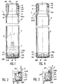
- the telescoped ammunition shown in Figure 1 comprises, in a manner known per se, a plastic case 2 consisting of a cylindrical casing 3 and two plugs respectively front 4 and rear 5, a projectile 6 (partially shown in lines mixed) and a propellant charge 7 housed inside the case 2, and an ignition device 8 of the propellant charge 7.
- the case and the front and rear plugs are made for example of polycarbonate.
- the front plug 4 is constituted by a ring 4a extended at one end by an annular seal 10 with lip 10a, the latter having an external diameter, before mounting, greater than the internal diameter of the envelope 3.
- the ring 4a is engaged, on the side of its seal 10, inside the envelope 3, so that the body of the ring 4a is in sliding contact with the internal wall of the envelope 3, while the seal 10 is in tight contact with its lip 10a with said envelope 3.
- the ring 4a is engaged in the envelope 3 until a shoulder 11 provided on the external surface of the ring 4a comes into contact with the adjacent end surface of the envelope 3. Concretely, the ring 4a is engaged over a length L1 inside the envelope 3.
- the rear plug 5 is a solid cylindrical body or base 5a which closes the other end of the envelope 3.
- the base 5a Towards one end, the base 5a also has an annular seal 13 with lip 13a.
- the outside diameters of the base 5a and of its lip seal 13 are such that the body of the base 5a is in sliding contact with the internal wall of the casing 3, while its seal 13 is in tight contact with its lip 13a with said envelope 3.
- the base 5a is engaged in the envelope 3 until a shoulder 14 provided on the external surface of the base 5a comes into contact with the adjacent end surface of the envelope 3. Concretely, the base 5a is engaged over a length L2 inside the envelope 3.
- the gas sealing means consisting of seals 10 and 13 also include an annular expansion groove 15 provided at the outer periphery of the body of the ring 4a.
- means for sealing external agents in particular moisture, constituted by an annular seal 16 received in an external annular groove in the body of the ring 4a, by an annular seal 17 received. in an external annular groove of the body of the base 5a, and by a plastic cover 20 welded on a surface 21 arranged at the end of the ring 4a.
- the ammunition 1 is equipped with axial retaining means for the ring 4a and the base 5a as long as the case 2 is not subjected to the pressure increase resulting from the initiation of the propellant charge after the munition has been put in place. in the barrel.
- these means of retained are constituted by radial pins 25 which pass through the casing 3 and which penetrate respectively inside the body of the ring 4a and the body of the base 5a.
- the increase in pressure inside the case 2 causes an increase in the diameter of the envelope 3 which will stick to the inner wall of the combustion chamber.
- the front 4 and rear 5 plugs are stiffened by metal reinforcements.
- the metal ring 26 is mounted on the side of the outer end face of the ring 4a by being either forcibly engaged in an annular groove provided at the end surface of the ring 4a, or embedded in the ring 4a during the molding operation thereof.
- a similar arrangement is provided for the metal ring 27 which reinforces the rigidity of the base 5a.
- the rings 26 and 27 have external diameters close to the internal diameter of the envelope 3 and are located outside of the latter to prevent their expansion causing rupture of the envelope 3. However, they are close enough to the envelope 3 to prevent the plastic from creeping between them and the envelope 3.
- Reinforcements at the base 5a where the maximum pressure is exerted during the firing of the projectile complementary may advantageously be provided in the form of a metal plate 28 covering the external face of the base 5a.
- the aforementioned ring 27 can advantageously be secured to this plate 28, the base 5a then being molded onto it (FIG. 3).
- the plate 28 pierced with a central opening for the passage of the ignition device 8 is maintained by the latter once it is screwed into the axial passage passing through the plug 5.
- the front 4 and rear 5 plugs remain linked to the casing 2 by means of the pins 25 until the ammunition is loaded into the chamber of the barrel tube.
- the pressure inside the munition is such that the pins 25 will either shear or deform sufficiently to allow the translation of the ring 4a and the base 5a, the latter always remaining linked to the envelope 2, so that it can then be extracted simultaneously with the envelope once the projectile has been fired.
- the gas-tightness means at the level of the base 5a of the ammunition 1 can be completed by a metal ring 30 in the form frusto-conical tightly fitted inside the casing 2 and which comes to bear against the lip 13a, or by an annular rubber seal 31 disposed on the end of the lip 13a, as shown in Figure 3.
- the pins 25 which ensure the axial retention of the front 4 and rear 5 plugs can be replaced by ultrasonic welds 35 made at the shoulders 11 of the ring 4a and 14 of the base 5a, as shown in FIG. 4.
- the pins 25 and the ultrasonic welds 35 can be replaced by elastomer seals.
- an axial clearance of 1 to 3 mm is left between the shoulder 11 of the ring 4a and the adjacent free end surface of the casing 2, and an equivalent clearance between the shoulder 14 of the base 5a and l adjacent free end of the envelope 3.
- These annular spaces are filled with an elastomer seal 36 which will ensure the axial maintenance of the ring 4a and of the base 5a with respect to the envelope 3.
- the ring 4a and the base 5a can move in translation without breaking the seals 36. It may thus be possible to remove the lips 10a and 13a from the seals 10 and 13, that is to say stressed parts likely to see their mechanical characteristics deteriorate over time. In this case, the ring 4a and the base 5b are engaged in tight contact in the casing 3.
- the metal reinforcement of the front ring 4a consisting of the metal ring 26 can be replaced by a rigid annular element 38 in the form of a disc which comes to fit, for example on the front end of the ring 4a, as shown in FIG. 4.
- a rigid annular element 38 in the form of a disc which comes to fit, for example on the front end of the ring 4a, as shown in FIG. 4.
- such an element can be attached to the base 5a and replace the metal ring 27 and / or the plate 28.
- the ammunition 1 is advantageously supplemented by means which make it possible to maintain the projectile 6 axially inside the ammunition 1 before the initiation of the propellant charge 7.
- the ammunition 1 illustrated in FIGS. 6 and 7 are equipped with sub-calibrated arrow type projectiles 6a.
- a type of projectile 6a comprises a shoe 40 which surrounds the front part of the projectile, and it ends in a tail unit 41. At its front part, the shoe 40 comes into contact with the internal surface of the ring 4a with interposition of a belt 42 to ensure a good seal at this level.
- the projectile 6a is kept aligned in the axis of the ammunition 1 by means of an annular shoulder 43 projecting from the internal wall of the ring 4a and against which the surface of end of the shoe 40. When firing, this shoulder 43 is sheared.
- the axial retention of the projectile 6a can be completed by the ignition device 8 axially aligned with the projectile. It suffices for this to rest the tail 41 on a ring 44 attached to the adjacent end surface of the ignition device 8 and to provide notches there for example in which are housed the fins 41a of the tail 41.
- the projectile 6a is kept aligned in the axis of the ammunition 1 by means of an elastic ring 45 attached in part in an annular groove 46 provided in the internal wall of the ring 4a and against which bears on the end surface of the shoe 40.
- an elastic ring 45 attached in part in an annular groove 46 provided in the internal wall of the ring 4a and against which bears on the end surface of the shoe 40.
- the axial retention of the projectile 41 can be completed at its empennage 41 by a wedge 49 such as that described in the document FR-A-2 647 891.
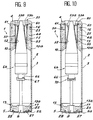
- the means for holding the projectile in the axis of the ammunition and as illustrated in Figures 8 to 10 relate to ammunition 1 equipped with 6b full caliber projectiles.
- the projectile 6b carries at its front part a cap 50 which has an internal profile corresponding to the external profiles of the ballistic warhead 51 and of the external surface 52 of the front part of the projectile 6b.
- the cap 50 made integral with the projectile by bonding, comprises an internal crown 53a and a crown external 53b connected by radial partitions (not shown) and by a conical partition 55, the external crown 53b being in close contact with the ring 4a.
- the axial retention of the projectile 6b is ensured by elastic ring 60 attached in part in a groove 61 provided on the internal surface of the ring 4a and against which the free end surface of the cap 50.
- the axial retention of the projectile is completed by the ignition device 8, the end of which engages in a housing 63 arranged at the rear part of the projectile 6b.
- the projectile 6b is equipped with a tracer 66 at its rear part, -if although it is not possible to penetrate the ignition device 8 in a housing at the rear of the projectile 6b.
- a crown 67 can be provided attached to the end of the ignition device 8 and on which the tracer 66 comes to bear.
- the projectile 6b also comprises at its rear part a tracer 66, and the means for axially retaining the projectile 6b are here supplemented by a threaded sleeve 70 which engages on a thread arranged around the tracer 66, and in which is housed the end of the ignition device 8.
- the shearing of the threads occurs during the pressure build-up, so that one can play on their dimensions and / or their number to control the uncocking effort, that is to say the one from which the projectile 6b leaves the case.
Landscapes
- Engineering & Computer Science (AREA)
- General Engineering & Computer Science (AREA)
- Portable Nailing Machines And Staplers (AREA)
- Axle Suspensions And Sidecars For Cycles (AREA)
- Lubricants (AREA)
- Spark Plugs (AREA)
Applications Claiming Priority (2)
| Application Number | Priority Date | Filing Date | Title |
|---|---|---|---|
| FR9109724A FR2679991B1 (fr) | 1991-07-31 | 1991-07-31 | Perfectionnements apportes a une munition en particulier du type telescope. |
| FR9109724 | 1991-07-31 |
Publications (2)
| Publication Number | Publication Date |
|---|---|
| EP0526316A1 EP0526316A1 (fr) | 1993-02-03 |
| EP0526316B1 true EP0526316B1 (fr) | 1996-01-03 |
Family
ID=9415769
Family Applications (1)
| Application Number | Title | Priority Date | Filing Date |
|---|---|---|---|
| EP92402145A Expired - Lifetime EP0526316B1 (fr) | 1991-07-31 | 1992-07-24 | Munition en particulier du type télescopé |
Country Status (4)
| Country | Link |
|---|---|
| EP (1) | EP0526316B1 (no) |
| DE (1) | DE69207300T2 (no) |
| FR (1) | FR2679991B1 (no) |
| NO (1) | NO176851C (no) |
Families Citing this family (3)
| Publication number | Priority date | Publication date | Assignee | Title |
|---|---|---|---|---|
| FR2702553B1 (fr) * | 1993-03-12 | 1995-04-28 | Giat Ind Sa | Munition de type télescopée. |
| FR2702555B1 (fr) * | 1993-03-12 | 1995-04-28 | Giat Ind Sa | Etui pour une munition de type télescopée. |
| FR2717570B1 (fr) * | 1994-03-16 | 1996-05-10 | Giat Ind Sa | Munition comportant un appoint anti-usure. |
Family Cites Families (3)
| Publication number | Priority date | Publication date | Assignee | Title |
|---|---|---|---|---|
| US3897729A (en) * | 1970-05-02 | 1975-08-05 | Schirnecker Hans Ludwig | Cartridge for firearms |
| FR2647891B1 (fr) * | 1989-06-01 | 1994-05-20 | Etat Francais Delegue Armement | Dispositif de maintien d'un projectile sous-calibre relativement a l'enveloppe d'une munition telescopee |
| FR2647890A1 (fr) * | 1989-06-01 | 1990-12-07 | France Etat Armement | Dispositif de maintien d'un projectile relativement a l'enveloppe d'une munition telescopee |
-
1991
- 1991-07-31 FR FR9109724A patent/FR2679991B1/fr not_active Expired - Lifetime
-
1992
- 1992-07-24 EP EP92402145A patent/EP0526316B1/fr not_active Expired - Lifetime
- 1992-07-24 DE DE69207300T patent/DE69207300T2/de not_active Expired - Lifetime
- 1992-07-30 NO NO922999A patent/NO176851C/no unknown
Also Published As
| Publication number | Publication date |
|---|---|
| NO176851B (no) | 1995-02-27 |
| FR2679991A1 (fr) | 1993-02-05 |
| NO176851C (no) | 1995-06-07 |
| NO922999D0 (no) | 1992-07-30 |
| NO922999L (no) | 1993-02-01 |
| EP0526316A1 (fr) | 1993-02-03 |
| FR2679991B1 (fr) | 1993-10-29 |
| DE69207300D1 (de) | 1996-02-15 |
| DE69207300T2 (de) | 1996-05-30 |
Similar Documents
| Publication | Publication Date | Title |
|---|---|---|
| EP0640205B1 (fr) | Etui pour munition de type telescopee | |
| EP0526317B1 (fr) | Munition, en particulier du type télescopé | |
| EP0463904B1 (fr) | Elément de douille à tube combustible, munition à douille semi-combustible incorporant cet élément et procédé de chargement de cette munition | |
| FR2526151A1 (fr) | Munition encartouchee constituee par un projectile et une douille combustible ou partiellement combustible reliee a celui-ci | |
| EP1181498B1 (fr) | Tube allumeur pour une munition d'artillerie | |
| EP0491614A1 (fr) | Ceinture dérapante pour projectile de tout calibre et son procédé de réalisation | |
| EP0526316B1 (fr) | Munition en particulier du type télescopé | |
| EP0401115B1 (fr) | Dispositif de maintien d'un projectile sous calibré relativement à l'enveloppe d'une munition télescopée | |
| EP1549901B1 (fr) | Ceinture d'etancheite pour projectile et munition equipee d'une telle ceinture | |
| EP1712873A1 (fr) | Dispositif d'adaptation d'un obus de mortier dans un canon | |
| EP0471617B1 (fr) | Ceinture d'étanchéité pour projectile flèche | |
| EP0691520B1 (fr) | Dispositif solidarisant deux conteneurs et conteneur associé à un tel dispositif | |
| EP0681679B1 (fr) | Conteneur pour charge propulsive pouvant etre rendu solidaire d'un autre conteneur | |
| EP1533590B1 (fr) | Obus explosif ayant une tenue aux chocs améliorée | |
| FR2665762A1 (fr) | Projectiles. | |
| EP0594482A1 (fr) | Boîtier pour charge propulsive | |
| EP0580511B1 (fr) | Ceinture d'étanchéité de projectile flèche | |
| FR2657408A1 (fr) | Organe de retenue d'un joint d'etancheite annulaire coulissant dans un systeme telescopique. | |
| WO2021044065A1 (fr) | Obus anti-aérien pour munition télescopée à double déverrouillage | |
| FR2719373A1 (fr) | Dispositif de propulsion à portées variables pour grenade anti-émeutes. | |
| EP0147314B1 (fr) | Culot obturateur en matériau non métallique | |
| EP1023573B1 (fr) | Lanceur a etancheite amelioree pour munitions du type comportant un lanceur associe a un sous-projectile | |
| EP0674150B1 (fr) | Munition comportant un appoint anti-usure | |
| EP0763707A1 (fr) | Dispositif d'étanchéité monté entre l'enveloppe et le culot d'un obus cargo | |
| FR2738908A1 (fr) | Dispositif de freinage aerodynamique d'une sous-munition ejectee d'un obus cargo en etant animee d'un mouvement de rotation |
Legal Events
| Date | Code | Title | Description |
|---|---|---|---|
| PUAI | Public reference made under article 153(3) epc to a published international application that has entered the european phase |
Free format text: ORIGINAL CODE: 0009012 |
|
| AK | Designated contracting states |
Kind code of ref document: A1 Designated state(s): CH DE GB IT LI NL SE |
|
| 17P | Request for examination filed |
Effective date: 19930225 |
|
| 17Q | First examination report despatched |
Effective date: 19940530 |
|
| GRAA | (expected) grant |
Free format text: ORIGINAL CODE: 0009210 |
|
| AK | Designated contracting states |
Kind code of ref document: B1 Designated state(s): CH DE GB IT LI NL SE |
|
| PG25 | Lapsed in a contracting state [announced via postgrant information from national office to epo] |
Ref country code: NL Free format text: LAPSE BECAUSE OF FAILURE TO SUBMIT A TRANSLATION OF THE DESCRIPTION OR TO PAY THE FEE WITHIN THE PRESCRIBED TIME-LIMIT Effective date: 19960103 Ref country code: IT Free format text: LAPSE BECAUSE OF FAILURE TO SUBMIT A TRANSLATION OF THE DESCRIPTION OR TO PAY THE FEE WITHIN THE PRE;WARNING: LAPSES OF ITALIAN PATENTS WITH EFFECTIVE DATE BEFORE 2007 MAY HAVE OCCURRED AT ANY TIME BEFORE 2007. THE CORRECT EFFECTIVE DATE MAY BE DIFFERENT FROM THE ONE RECORDED.SCRIBED TIME-LIMIT Effective date: 19960103 |
|
| REF | Corresponds to: |
Ref document number: 69207300 Country of ref document: DE Date of ref document: 19960215 |
|
| GBT | Gb: translation of ep patent filed (gb section 77(6)(a)/1977) |
Effective date: 19960123 |
|
| RAP2 | Party data changed (patent owner data changed or rights of a patent transferred) |
Owner name: CTA INTERNATIONAL |
|
| PG25 | Lapsed in a contracting state [announced via postgrant information from national office to epo] |
Ref country code: SE Effective date: 19960403 |
|
| NLT2 | Nl: modifications (of names), taken from the european patent patent bulletin |
Owner name: CTA INTERNATIONAL |
|
| NLV1 | Nl: lapsed or annulled due to failure to fulfill the requirements of art. 29p and 29m of the patents act | ||
| PG25 | Lapsed in a contracting state [announced via postgrant information from national office to epo] |
Ref country code: LI Effective date: 19960731 Ref country code: CH Effective date: 19960731 |
|
| PLBE | No opposition filed within time limit |
Free format text: ORIGINAL CODE: 0009261 |
|
| STAA | Information on the status of an ep patent application or granted ep patent |
Free format text: STATUS: NO OPPOSITION FILED WITHIN TIME LIMIT |
|
| 26N | No opposition filed | ||
| REG | Reference to a national code |
Ref country code: CH Ref legal event code: PL |
|
| REG | Reference to a national code |
Ref country code: GB Ref legal event code: IF02 |
|
| PGFP | Annual fee paid to national office [announced via postgrant information from national office to epo] |
Ref country code: GB Payment date: 20110701 Year of fee payment: 20 Ref country code: DE Payment date: 20110708 Year of fee payment: 20 |
|
| REG | Reference to a national code |
Ref country code: DE Ref legal event code: R071 Ref document number: 69207300 Country of ref document: DE |
|
| REG | Reference to a national code |
Ref country code: DE Ref legal event code: R071 Ref document number: 69207300 Country of ref document: DE |
|
| REG | Reference to a national code |
Ref country code: GB Ref legal event code: PE20 Expiry date: 20120723 |
|
| PG25 | Lapsed in a contracting state [announced via postgrant information from national office to epo] |
Ref country code: GB Free format text: LAPSE BECAUSE OF EXPIRATION OF PROTECTION Effective date: 20120723 Ref country code: DE Free format text: LAPSE BECAUSE OF EXPIRATION OF PROTECTION Effective date: 20120725 |