EP0526075A2 - Interferometrische Teststation für Kugellager - Google Patents
Interferometrische Teststation für Kugellager Download PDFInfo
- Publication number
- EP0526075A2 EP0526075A2 EP92306662A EP92306662A EP0526075A2 EP 0526075 A2 EP0526075 A2 EP 0526075A2 EP 92306662 A EP92306662 A EP 92306662A EP 92306662 A EP92306662 A EP 92306662A EP 0526075 A2 EP0526075 A2 EP 0526075A2
- Authority
- EP
- European Patent Office
- Prior art keywords
- measurement beam
- interferogram
- interferometer
- path length
- optical path
- Prior art date
- Legal status (The legal status is an assumption and is not a legal conclusion. Google has not performed a legal analysis and makes no representation as to the accuracy of the status listed.)
- Withdrawn
Links
Images

Classifications
-
- G—PHYSICS
- G01—MEASURING; TESTING
- G01B—MEASURING LENGTH, THICKNESS OR SIMILAR LINEAR DIMENSIONS; MEASURING ANGLES; MEASURING AREAS; MEASURING IRREGULARITIES OF SURFACES OR CONTOURS
- G01B11/00—Measuring arrangements characterised by the use of optical techniques
- G01B11/24—Measuring arrangements characterised by the use of optical techniques for measuring contours or curvatures
- G01B11/2441—Measuring arrangements characterised by the use of optical techniques for measuring contours or curvatures using interferometry
-
- G—PHYSICS
- G01—MEASURING; TESTING
- G01B—MEASURING LENGTH, THICKNESS OR SIMILAR LINEAR DIMENSIONS; MEASURING ANGLES; MEASURING AREAS; MEASURING IRREGULARITIES OF SURFACES OR CONTOURS
- G01B11/00—Measuring arrangements characterised by the use of optical techniques
- G01B11/24—Measuring arrangements characterised by the use of optical techniques for measuring contours or curvatures
- G01B11/2408—Measuring arrangements characterised by the use of optical techniques for measuring contours or curvatures for measuring roundness
Definitions
- This invention relates generally to optical metrology apparatus and method and, in particular, to method and apparatus for determining a roundness of an object, in particular a ball bearing.
- Conventional practice for testing or inspecting the roundness of ball bearings includes mechanical sorting gauges and stylus profiling.
- Conventional practice also includes the use of optical inspection systems, in particular optical imaging systems.
- Visible-wavelength interferometers are widely employed for high precision displacement measurement and surface profilometry. These interferometers generally include either single wavelength or dual wavelength optical sources.
- a two-wavelength phase-shifting interferometer employs two laser sources for reconstructing steep surface profiles, such as aspheric surfaces.
- a 256 X 256 detector array is used and the technique computes an equivalent phas independently for each detector.
- the measuring apparatus consists of a Fizeau interferometer, a rotating air spindle unit, and a microcomputer system.
- the raceway shape along the cross section is measured at each rotating angle until the entire surface data are stored in the computer memory.
- the fringe data at each angle are displayed two dimensionally using a TV frame memory to obtain a peri-interferogram.
- a parallel laser beam is focused to a virtual point at the center of the sphere, and in another arrangement the beam is focused at the spherical surface. It is shown on the basis of theory, and verified experimentally, that focusing the beam on the surface of the sphere is the more satisfactory arrangement. The technique was used to measure the roundness of spheres.
- a single wavelength or multiple wavelength interferometer employed for determining a roundness of a spherical body while the body is in rolling motion through a test station, wherein a linear light pattern is projected upon a surface of the rolling body for generating a interferogram that is swept across a surface of a light sensitive detector element.
- a test system includes an interferometer having a reference beam and a measurement beam.
- the measurement beam is disposed for illuminating a surface of the object while the object is in rolling motion.
- a cylindrical lens is provided for forming the measurement beam into a linear, stripe-like pattern that intersects the geometric center of the ball. An imaginary line traced out by the center of the ball as it rolls on a track coincides with the linear pattern at the focus of the cylindrical lens.
- the measurement beam reflects, from the surface of the object, to a beamsplitter that combines the reflected measurement beam with a reflected reference beam.
- the test system further includes apparatus, such as a Charge Coupled Device (CCD) imager, optically coupled to an output of the interferometer for recording a two dimensional interferogram from a substantially one dimensional interferogram that is scanned across the imager during a forward motion of the object.
- CCD Charge Coupled Device
- the interferogram results from a change in an optical path length of the measurement beam, relative to an optical path length of the reference beam.
- the movement of the ball within the measurement beam produces a two dimensional interferogram representative of the surface contours of the ball.
- the test system further includes a processor, coupled to an output of the imager, for comparing the interferogram recorded by the imager to a reference interferogram previously recorded from a surface of an object known to have a radius of curvature and surface uniformity within the predetermined tolerances.
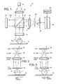
- a ball bearing 12 rolls across a flat surface 14.
- the surface 14 may be an optical flat or a pair of rails made mechanically smooth.
- the direction of motion of the ball bearing 12 is indicated by the arrow A while the rotation of the ball bearing 12 is indicated by the arrow B.
- roundness is intended to describe a characteristic of a surface of an object having, ideally, a constant radius of curvature. Any deviation from a constant radius causes the surface of the object to deviate from an intended or desired degree of roundness. By example, a deviation from a desired roundness may be the result of the object being improperly fabricated with a variable radius, or may result from a surface defect, such as a dent.
- a test station for ball bearings it should be kept in mind that the teaching of the invention is applicable to the testing of spherical or circular cylindrical objects in general.
- the test station 10 includes an optical source 16 having a single significant wavelength output.
- a laser diode operating at approximately 785 nanometers is one suitable embodiment for the source 16.
- a collimating lens 18 receives the output of the source 16 and collimates same for application to an interferometer.
- the interferometer includes a non-polarizing beamsplitter 20 that provides a reference beam 20a and a measurement beam 20b.
- a mirror 22 is disposed in a reference arm of the interferometer for reflecting the reference beam 20a back towards the beamsplitter 20.
- a measurement leg of the interferometer includes a cylindrical lens 24 that provides a linear, stripe-like measurement beam having a locus of focus points indicated by the letter C.
- the cylindrical lens 24 forms the measurement beam into a linear pattern that intersects the geometric center of the ball bearing 12.
- An imaginary line traced out by the center of the ball bearing 12, as it rolls, coincides with the linear pattern at the focus of the cylindrical lens.
- the mirror 22 is positioned such that the optical path length of the reference beam 20a is equal to the optical path length of the measurement beam 20b, as referenced to the locus of focus points C.
- the measurement beam reflects from the surface of the ball bearing 12 back towards the beamsplitter 20.
- a combined measurement beam and object beam are provided to a focussing lens 26 that has a focal point coincident with a slit aperture of a spatial filter 28.
- An imaging device such as a CCD imager 30, is disposed behind the spatial filter 28 and receives the reflected reference beam 20a and the reflected measurement beam 20b.
- the ball bearing 12 rolls it generates a flat, two-dimensional interferogram on the imaging surface 30a of the CCD imager 30.
- This interferogram is recorded by a data processor 32 that is coupled to an output of the CCD imager 30.
- the data processor 32 compares the recorded interferogram to an interferogram stored in a memory 34.
- the interferogram stored in the memory 34 is that obtained from a reference ball bearing having a roundness within an acceptable tolerance level.
- the amount of deviation between the two interferograms is indicative of a deviation of the roundness of the ball bearing 12 from that of the reference ball bearing.
- Data processor 32 searches for the dark fringes in the interferograms and determines the locations of the dark fringes in two-dimensional coordinates. If the two interferograms are determined by the processor 32 to deviate by more than some predetermined amount, the ball bearing 12 is determined to have a roundness outside of an acceptable tolerance.
- the linear image E projected onto the CCD imager 30 is perpendicular to the plane of the drawing.
- the linear image E has, at each instant, interference information characteristic of a portion of a meridian on the illuminated portion of the ball bearing 12.
- the linear image E moves across the imaging surface 30a of the CCD imager 30 in a bottom-to-top fashion.
- An inherent persistence of the CCD imager 30 momentarily stores a 2-dimensional interferogram corresponding to a relatively large arc of the ball bearing 12. That is, due to the rolling motion of the ball bearing 12 the substantially one-dimensional linear image E is swept across the CCD imager 30 to form a two-dimensional interferogram.
- This interferogram results from changes in the optical path length of the measurement leg relative to the reference leg, the changes in optical path length being due to the presence of the surface of the ball bearing 12.
- the desired velocity of the rolling ball bearing 12 is a function of several parameters. These include the radius of the ball bearing 12 and the persistence of the selected CCD imager 30. A typical persistence for commercially available CCD imagers is within a range of approximately 0.05 seconds to approximately one second, and is related to the illumination intensity. Preferably, the velocity of the rolling ball bearing is such that the generated two-dimensional interferogram represents a significant portion of the surface area of the ball bearing 12, while scanning the linear image E across the surface 30a of the imager 30 within a time that is less than the persistence time of the selected CCD. Ideally, the ball bearing 12 makes one complete revolution as it passes through the locus of focus points C.
- the CCD imager 30 may be read out several times to obtain the complete interferogram, or may be read out once at the end of the transit of the ball bearing through the test station. Measurement accuracies of 0.01 micrometers are obtainable with the roundness tester of the invention.
- Figs. 2 and 3 each show a view of the optical imaging geometry of Fig. 1 in an unfolded configuration.
- elements that correspond to elements in Fig. 1 are numbered the same.
- the ball bearing 12 travel is, as depicted by the arrow F, parallel to the plane of the drawing whereas in Fig. 3 the arrow G indicates that the ball bearing 12 travel is perpendicular and into the plane of the drawing.
- Fig. 4 depicts a second embodiment of a test station 10' that employs two-wavelength interferometry.
- elements having reference numbers the same as the embodiment of Fig. 1 operate in the same fashion. Differences between these embodiments include a dual wavelength optical source 16' comprised of, by example two single mode laser diodes or a single, multi-mode laser diode. A source generating significant two optical wavelengths in the vicinity of 785 nanometers is one suitable embodiment.
- the test station 10' includes an additional non-polarizing beamsplitter 36 that provides two beams to a dual measurement channel.
- a first channel includes an interference filter 38a that preferentially passes one of the two source wavelengths.
- This first portion of the combined measurement beam and object beam is provided to a focussing lens 26a that has a focal point coincident with a slit aperture of a spatial filter 28a.
- An imaging device such as a CCD imager 30a, is disposed behind the spatial filter 28a and receives the first portion of the reflected reference beam 20a and the reflected measurement beam 20b.
- a second measurement channel includes an interference filter 38b that preferentially passes the other one of the two source wavelengths.
- This second portion of the combined measurement beam and object beam is provided to a focussing lens 26b having a focal point coincident with a slit aperture of a spatial filter 28b.
- a second CCD imaging device 30b is disposed behind the spatial filter 28b and receives the second portion of the reflected reference beam 20a and the reflected measurement beam 20b.
- the processor 32 is coupled to both imagers and receives interferograms from each.
- An equivalent phase is computed as in the above referenced U.S. Patent 4,832,489.
- a suitable separation for the two wavelengths is approximately 30 nanometers to achieve high accuracy measurements.
- the exact separation between wavelengths is a function of the required measurement accuracy.
- a large number of ball bearings 12 may be individually fed from a container such that each rolls through the test station 10.
- apparatus may be included for triggering the operation of the processor 32 to obtain the 2-dimensional interferogram from the CCD imager 30.
- a Hall-effect device can be mounted for detecting the presence of the ball bearing 12 as it enters the locus of focus points C.
- a light beam transmitter and receiver can be so disposed such that the ball bearing 12 interrupts the beam as it enters the locus of focus points C, the beam remaining interrupted until the ball bearing exits this region. It is also within the scope of the invention to provide a diverting apparatus, operating under the control of the processor 32, for diverting from a normal path of travel any ball bearing determined to have an unacceptable roundness.
- test stations 10 and 10' may be integrated with a production line facility so as to obtain, in a rapid manner, a precise indication as to whether a roundness of a ball bearing under test is within a predetermined acceptable roundness tolerance.
Landscapes
- Physics & Mathematics (AREA)
- General Physics & Mathematics (AREA)
- Length Measuring Devices By Optical Means (AREA)
- Instruments For Measurement Of Length By Optical Means (AREA)
Applications Claiming Priority (2)
| Application Number | Priority Date | Filing Date | Title |
|---|---|---|---|
| US07/739,628 US5210591A (en) | 1991-08-02 | 1991-08-02 | Interferometric ball bearing test station |
| US739628 | 2005-11-23 |
Publications (2)
| Publication Number | Publication Date |
|---|---|
| EP0526075A2 true EP0526075A2 (de) | 1993-02-03 |
| EP0526075A3 EP0526075A3 (en) | 1993-05-19 |
Family
ID=24973146
Family Applications (1)
| Application Number | Title | Priority Date | Filing Date |
|---|---|---|---|
| EP19920306662 Withdrawn EP0526075A3 (en) | 1991-08-02 | 1992-07-21 | Interferometric ball bearing test station |
Country Status (4)
| Country | Link |
|---|---|
| US (1) | US5210591A (de) |
| EP (1) | EP0526075A3 (de) |
| JP (1) | JPH0772683B2 (de) |
| KR (1) | KR930004754A (de) |
Cited By (2)
| Publication number | Priority date | Publication date | Assignee | Title |
|---|---|---|---|---|
| WO2000016038A1 (en) * | 1998-09-10 | 2000-03-23 | Warner-Lambert Company | Apparatus for surface image sensing and surface inspection of three-dimensional structures |
| US8718975B2 (en) | 2009-03-02 | 2014-05-06 | Rolls-Royce, Plc | Surface profile evaluation |
Families Citing this family (19)
| Publication number | Priority date | Publication date | Assignee | Title |
|---|---|---|---|---|
| DE4124223C2 (de) * | 1991-07-22 | 2001-07-26 | Zeiss Carl | Verfahren zur Auswertung von Interferogrammen und Interferometer |
| US5402234A (en) * | 1992-08-31 | 1995-03-28 | Zygo Corporation | Method and apparatus for the rapid acquisition of data in coherence scanning interferometry |
| JP3517903B2 (ja) * | 1993-06-21 | 2004-04-12 | 株式会社ニコン | 干渉計 |
| US5563706A (en) * | 1993-08-24 | 1996-10-08 | Nikon Corporation | Interferometric surface profiler with an alignment optical member |
| US5654798A (en) * | 1995-01-19 | 1997-08-05 | Tropel Corporation | Interferometric measurement of surfaces with diffractive optics at grazing incidence |
| US5793488A (en) * | 1995-07-31 | 1998-08-11 | Tropel Corporation | Interferometer with compound optics for measuring cylindrical objects at oblique incidence |
| US5719676A (en) * | 1996-04-12 | 1998-02-17 | Tropel Corporation | Diffraction management for grazing incidence interferometer |
| US5889591A (en) * | 1996-10-17 | 1999-03-30 | Tropel Corporation | Interferometric measurement of toric surfaces at grazing incidence |
| JPH10145567A (ja) * | 1996-11-08 | 1998-05-29 | Canon Inc | 画像読取装置 |
| US5777738A (en) * | 1997-03-17 | 1998-07-07 | Tropel Corporation | Interferometric measurement of absolute dimensions of cylindrical surfaces at grazing incidence |
| DE19714202A1 (de) * | 1997-04-07 | 1998-10-15 | Bosch Gmbh Robert | Vorrichtung zum optischen Prüfen von Oberflächen |
| JP3793888B2 (ja) * | 1999-02-04 | 2006-07-05 | 日本精工株式会社 | 玉軸受の検査方法 |
| US6580514B1 (en) * | 1999-04-28 | 2003-06-17 | Nec Corporation | Non-contact silicon melt surface evaluation method and system |
| JP3605010B2 (ja) * | 2000-08-08 | 2004-12-22 | 株式会社ミツトヨ | 表面性状測定器 |
| US20030169235A1 (en) * | 2002-03-07 | 2003-09-11 | Gron Mikkel Hartmann | Three dimensional track ball systems |
| JP2005140673A (ja) * | 2003-11-07 | 2005-06-02 | Olympus Corp | 非球面偏心測定装置及び非球面偏心測定方法 |
| US20100002238A1 (en) * | 2006-10-11 | 2010-01-07 | Koninklijke Philips Electronics N.V. | Laser interference device for touch screens |
| JP5188377B2 (ja) * | 2008-12-15 | 2013-04-24 | 株式会社ミツトヨ | 球体の真球度の測定方法および球体の曲率半径の測定方法 |
| DE102014223747B4 (de) * | 2014-11-20 | 2016-09-08 | Fraunhofer-Gesellschaft zur Förderung der angewandten Forschung e.V. | Vorrichtung und Verfahren zur Vermessung eines Höhenprofils einer Oberfläche unter Verwendung einer länglichen Blende |
Family Cites Families (6)
| Publication number | Priority date | Publication date | Assignee | Title |
|---|---|---|---|---|
| US3749500A (en) * | 1970-12-23 | 1973-07-31 | Gen Electric | Optical caliper and edge detector-follower for automatic gaging |
| FR2163862A5 (de) * | 1971-12-03 | 1973-07-27 | Anvar | |
| US3812376A (en) * | 1972-02-18 | 1974-05-21 | Agency Ind Science Techn | Device for controlling dimensional accuracy during machining of a cylindrical workpiece |
| US4131365A (en) * | 1974-09-13 | 1978-12-26 | Pryor Timothy R | Method and apparatus for determining object position and dimension using a diffraction wave |
| JPS60125511A (ja) * | 1983-12-12 | 1985-07-04 | Ntn Toyo Bearing Co Ltd | レ−ザ−光干渉による精密加工面検査装置 |
| US4917498A (en) * | 1987-06-15 | 1990-04-17 | Geary Joseph M | Arrangement for testing grazing hyperboloids and similar reflective solid bodies for shape deviations |
-
1991
- 1991-08-02 US US07/739,628 patent/US5210591A/en not_active Expired - Fee Related
-
1992
- 1992-07-21 EP EP19920306662 patent/EP0526075A3/en not_active Withdrawn
- 1992-08-01 KR KR1019920013893A patent/KR930004754A/ko not_active Ceased
- 1992-08-03 JP JP4206664A patent/JPH0772683B2/ja not_active Expired - Lifetime
Non-Patent Citations (2)
| Title |
|---|
| APPLIED OPTICS vol. 18, no. 16, 15 August 1979, pages 2881 - 2890 KLINGSPORN 'Use of a laser interferometric displacement-measuring system for noncontact positioning of a sphere on a rotation axis through its center and for measuring the spherical contour' * |
| APPLIED OPTICS vol. 24, no. 22, 15 November 1985, pages 3791 - 3796 NUNOME ET AL. 'Interferometer for measuring the surface shape of a ball bearing raceway' * |
Cited By (3)
| Publication number | Priority date | Publication date | Assignee | Title |
|---|---|---|---|---|
| WO2000016038A1 (en) * | 1998-09-10 | 2000-03-23 | Warner-Lambert Company | Apparatus for surface image sensing and surface inspection of three-dimensional structures |
| US6393141B1 (en) | 1998-09-10 | 2002-05-21 | Warner-Lambert Company | Apparatus for surface image sensing and surface inspection of three-dimensional structures |
| US8718975B2 (en) | 2009-03-02 | 2014-05-06 | Rolls-Royce, Plc | Surface profile evaluation |
Also Published As
| Publication number | Publication date |
|---|---|
| JPH0772683B2 (ja) | 1995-08-02 |
| EP0526075A3 (en) | 1993-05-19 |
| KR930004754A (ko) | 1993-03-23 |
| US5210591A (en) | 1993-05-11 |
| JPH05196440A (ja) | 1993-08-06 |
Similar Documents
| Publication | Publication Date | Title |
|---|---|---|
| US5210591A (en) | Interferometric ball bearing test station | |
| US4652131A (en) | Method and apparatus for making a contact-free measurement of the actual position and of the profile of a coarse surface | |
| US7643151B2 (en) | Optical measuring device for measuring a plurality of surfaces of an object to be measured | |
| US9581437B2 (en) | Interferometric non-contact optical probe and measurement | |
| US20040075843A1 (en) | Interferometer system of compact configuration | |
| Berger et al. | Non-contact metrology of aspheric surfaces based on MWLI technology | |
| JP2005530147A (ja) | 光路長および焦点を同時に走査する干渉光学システムおよび方法 | |
| US8411280B2 (en) | Surface shape measurement apparatus | |
| US9435640B2 (en) | Interferometer and method for measuring non-rotationally symmetric surface topography having unequal curvatures in two perpendicular principal meridians | |
| US20130044332A1 (en) | Surface profile measurement apparatus and alignment method thereof and an improved sub-aperture measurement data acquisition method | |
| US20070177156A1 (en) | Surface profiling method and apparatus | |
| US11073370B2 (en) | OCT measurement device with back-reflection | |
| US4009965A (en) | Method and apparatus for determining object dimension and other characteristics using diffraction waves | |
| GB2265215A (en) | Optical apparatus for measuring surface curvature | |
| JP3377820B2 (ja) | 表面の曲率の測定装置 | |
| EP3227633B1 (de) | Kontaktlose interferometrische optische sonde und messmethode | |
| JP2618377B2 (ja) | 無接触測定用のf−シータ補正されたテレセントリツク系対物鏡を有する装置 | |
| JPH10339616A (ja) | 物体形状の非接触測定装置および方法 | |
| US4946281A (en) | Laser profiler for high precision surface dimensional grouping apparatus and method | |
| US7898671B2 (en) | Interferometer having a mirror system for measuring a measured object | |
| CA1297285C (en) | High accuracy structured light profiler | |
| GB2135150A (en) | Optical inspection system | |
| Wang | Long-range optical triangulation utilising collimated probe beam | |
| JPH03243804A (ja) | 非球面の形状測定方法 | |
| US20250123095A1 (en) | Dynamic interferometer illuminator |
Legal Events
| Date | Code | Title | Description |
|---|---|---|---|
| PUAI | Public reference made under article 153(3) epc to a published international application that has entered the european phase |
Free format text: ORIGINAL CODE: 0009012 |
|
| AK | Designated contracting states |
Kind code of ref document: A2 Designated state(s): DE FR GB NL |
|
| PUAL | Search report despatched |
Free format text: ORIGINAL CODE: 0009013 |
|
| AK | Designated contracting states |
Kind code of ref document: A3 Designated state(s): DE FR GB NL |
|
| 17P | Request for examination filed |
Effective date: 19931029 |
|
| 17Q | First examination report despatched |
Effective date: 19950508 |
|
| STAA | Information on the status of an ep patent application or granted ep patent |
Free format text: STATUS: THE APPLICATION IS DEEMED TO BE WITHDRAWN |
|
| 18D | Application deemed to be withdrawn |
Effective date: 19950919 |