EP0526046A2 - Zusammengesetztes Hubventil und Verfahren - Google Patents
Zusammengesetztes Hubventil und Verfahren Download PDFInfo
- Publication number
- EP0526046A2 EP0526046A2 EP92306503A EP92306503A EP0526046A2 EP 0526046 A2 EP0526046 A2 EP 0526046A2 EP 92306503 A EP92306503 A EP 92306503A EP 92306503 A EP92306503 A EP 92306503A EP 0526046 A2 EP0526046 A2 EP 0526046A2
- Authority
- EP
- European Patent Office
- Prior art keywords
- valve
- cladding
- core
- poppet valve
- slug
- Prior art date
- Legal status (The legal status is an assumption and is not a legal conclusion. Google has not performed a legal analysis and makes no representation as to the accuracy of the status listed.)
- Withdrawn
Links
Images


Classifications
-
- F—MECHANICAL ENGINEERING; LIGHTING; HEATING; WEAPONS; BLASTING
- F01—MACHINES OR ENGINES IN GENERAL; ENGINE PLANTS IN GENERAL; STEAM ENGINES
- F01L—CYCLICALLY OPERATING VALVES FOR MACHINES OR ENGINES
- F01L3/00—Lift-valve, i.e. cut-off apparatus with closure members having at least a component of their opening and closing motion perpendicular to the closing faces; Parts or accessories thereof
- F01L3/02—Selecting particular materials for valve-members or valve-seats; Valve-members or valve-seats composed of two or more materials
-
- B—PERFORMING OPERATIONS; TRANSPORTING
- B21—MECHANICAL METAL-WORKING WITHOUT ESSENTIALLY REMOVING MATERIAL; PUNCHING METAL
- B21C—MANUFACTURE OF METAL SHEETS, WIRE, RODS, TUBES OR PROFILES, OTHERWISE THAN BY ROLLING; AUXILIARY OPERATIONS USED IN CONNECTION WITH METAL-WORKING WITHOUT ESSENTIALLY REMOVING MATERIAL
- B21C23/00—Extruding metal; Impact extrusion
- B21C23/22—Making metal-coated products; Making products from two or more metals
-
- B—PERFORMING OPERATIONS; TRANSPORTING
- B21—MECHANICAL METAL-WORKING WITHOUT ESSENTIALLY REMOVING MATERIAL; PUNCHING METAL
- B21C—MANUFACTURE OF METAL SHEETS, WIRE, RODS, TUBES OR PROFILES, OTHERWISE THAN BY ROLLING; AUXILIARY OPERATIONS USED IN CONNECTION WITH METAL-WORKING WITHOUT ESSENTIALLY REMOVING MATERIAL
- B21C33/00—Feeding extrusion presses with metal to be extruded ; Loading the dummy block
- B21C33/004—Composite billet
-
- B—PERFORMING OPERATIONS; TRANSPORTING
- B21—MECHANICAL METAL-WORKING WITHOUT ESSENTIALLY REMOVING MATERIAL; PUNCHING METAL
- B21K—MAKING FORGED OR PRESSED METAL PRODUCTS, e.g. HORSE-SHOES, RIVETS, BOLTS OR WHEELS
- B21K1/00—Making machine elements
- B21K1/20—Making machine elements valve parts
- B21K1/22—Making machine elements valve parts poppet valves, e.g. for internal-combustion engines
-
- B—PERFORMING OPERATIONS; TRANSPORTING
- B23—MACHINE TOOLS; METAL-WORKING NOT OTHERWISE PROVIDED FOR
- B23P—METAL-WORKING NOT OTHERWISE PROVIDED FOR; COMBINED OPERATIONS; UNIVERSAL MACHINE TOOLS
- B23P15/00—Making specific metal objects by operations not covered by a single other subclass or a group in this subclass
- B23P15/001—Making specific metal objects by operations not covered by a single other subclass or a group in this subclass valves or valve housings
- B23P15/002—Making specific metal objects by operations not covered by a single other subclass or a group in this subclass valves or valve housings poppet valves
-
- F—MECHANICAL ENGINEERING; LIGHTING; HEATING; WEAPONS; BLASTING
- F01—MACHINES OR ENGINES IN GENERAL; ENGINE PLANTS IN GENERAL; STEAM ENGINES
- F01L—CYCLICALLY OPERATING VALVES FOR MACHINES OR ENGINES
- F01L2301/00—Using particular materials
- F01L2301/02—Using ceramic materials
Definitions
- the present invention relates to poppet valves for internal combustion engines, and more particularly to a poppet valve fabricated of titanium and steel.
- valve train design In the design of reciprocating internal combustion engines more and more emphasis is being placed on light weight valve train components.
- One area of valve train design that is affected by such emphasis is in the design of intake and exhaust poppet valves wherein valves fabricated of titanium or titanium alloys are desirable because of their light weight, strength to weight ratio and corrosion resistance at high temperatures as compared with similar valves fabricated of steel.
- valve head One problem associated with the use of titanium or titanium-containing valves is that different parts of an engine valve, including the valve head, the stem and the stem end or tip, are required to have different properties for optimum valve performance.
- the head portion must be highly heat resistant, while mechanical strength and wear resistance are requirements for the stem portion.
- the tip and the seat portion of the head are required to be wear resistant.
- Bimetallic valves have been fabricated by extruding a bimetallic billet, as shown in United States Patent No. 2,431,853; however, such processes do not include the desired combination of light weight, heat resistance in the head portion, and a wear resistant stem.
- an object of the present invention to provide a light weight poppet valve with maximum wear resistance in the stem and tip portions of the valve and preferrably in the stem, tip and seat portions.
- Another object is to provide a valve as above eliminating or at least minimizing assembly operations.
- Another object is to provide a valve as above formed as a core of a light weight material such as titanium with a cladding of a wear resistant material such as steel in the regions of the stem, tip and seat.
- Another object of the invention is to provide a valve as above by means of an extrusion process which improves the life of the extrusion die, and avoids galling of the valve stem and fillet.
- the present invention meets the objectives by means of a process wherein a bimetallic slug comprising a titanium portion and a steel portion is formed and then is advanced through an extrusion die steel end first to form a valve blank, after which the blank is subjected to a restriking process to form the final valve shape.
- the result of this process is a poppet valve which takes advantage of the described properties of both materials.
- the head and major portion of the stem comprises titanium and wherein a portion of the stem is clad with steel, and wherein the tip is steel.
- the steel cladding extends a sufficient distance from the tip of the valve toward the stem such that when the valve is assembled in the valve guide of the engine, only the steel clad portion will contact the valve guide.
- the tip, stem and seat portion are clad with steel; and in accordance with a further embodiment a titanium core is fully encapsulated by the steel cladding.
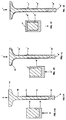
- FIG. 1A there is illustrated a poppet valve 10 fabricated in accordance with the invention, wherein the head portion 12 of the valve is titanium, the stem portion 14 comprises a core 15 of titanium with a cladding 16 of an iron based alloy such as steel, the cladding also defining the tip 18 of the valve.
- This configuration provides an engine valve which takes advantage of the light weight of titanium while retaining the wear resistance of steel along the stem of the valve where the valve is in sliding engagement with a valve guide, and at the tip where the valve engages a tappet or cam follower. Also, the area of the keeper groove 20 adjacent the tip can be hardened.
- a bimetallic slug 22 from which the valve 10 depicted in Fig. 1A is formed as will be described in detail below.
- the slug comprises a core 24 with the cladding formed initially as a cup member 26 partially enclosing the core then friction or C-D welded to the core.
- Fig. 1C the valve 10′ is formed with the cladding 16′ extending to enclose the entire stem portion 14 and seat area 17.
- Fig. 1D illustrates a slug 22′ used to form the Fig. 1C embodiment wherein the cladding 26′ extends the full lengh of the core 24′ and wherein the core is pressed into the cladding member to form the slug.
- This configuration provides improved wear characteristics for the seat in applications using iron, steel or powdered metal seat inserts.
- Fig. 1E illustrates a third embodiment wherein the cladding 16 ⁇ completely encloses the core, the valve being formed from the slug 22 ⁇ shown in Fig. 1F wherein the clad slug is closed by a cap 19 of an iron based alloy which is friction welded or otherwise attached to the slug.
- the valve 10 is preferably manufactured by an extrusion process carried out at between 1600°F and 1900°F, followed by restriking and finish machining.
- the composite slug 22 is inserted steel end first into an extrusion die set 28 to produce a composite blank 30.
- the blank 30 is then subjected to a restriking process as shown in Fig. 3 using a restrike die set 32 to form the valve into its final shape prior to finish machining.
- FIGS. 4A-4D While the above tests were conducted using slugs or billets as shown in FIGS. 1A-1F, other composite slug configurations, as shown in FIGS. 4A-4D, can be expected to yield similar results.
- the steel portion can be friction or C-D welded to the titanium portion
- example Fig. 4B illustrates a slug configuration wherein the steel cladding 26 is crimp-locked onto the titanium portion.
- the slugs shown in Figs. 4A-4D are configured to produce the valve shown in Fig. 1A. It can be appreciated, however, that the slugs shown in Figs. 4B and 4D can be modified to produce slugs from which the Figs. 1C and 1E configurations can be fabricated.
- the composite valve of the invention has been described as comprising a titanium core to which a cladding of steel is applied.
- the inventive process can be applied to a valve wherein the core is aluminum or some other light weight material and the claddding is formed of a material other than steel.
- Examples of such combinations are a core of 600 series aluminum and a cladding of SAE-1547 steel; a core of ZK60A magnesium alloy with a cladding of SAE-1547 steel and a core of Ti-6-2-4-2s titanium and a cladding of an austenitic alloy such as SAE EV-12.
Landscapes
- Engineering & Computer Science (AREA)
- Mechanical Engineering (AREA)
- General Engineering & Computer Science (AREA)
- Chemical & Material Sciences (AREA)
- Combustion & Propulsion (AREA)
- Pressure Welding/Diffusion-Bonding (AREA)
Applications Claiming Priority (2)
| Application Number | Priority Date | Filing Date | Title |
|---|---|---|---|
| US736984 | 1985-05-22 | ||
| US73698491A | 1991-07-29 | 1991-07-29 |
Publications (2)
| Publication Number | Publication Date |
|---|---|
| EP0526046A2 true EP0526046A2 (de) | 1993-02-03 |
| EP0526046A3 EP0526046A3 (en) | 1993-08-25 |
Family
ID=24962129
Family Applications (1)
| Application Number | Title | Priority Date | Filing Date |
|---|---|---|---|
| EP19920306503 Withdrawn EP0526046A3 (en) | 1991-07-29 | 1992-07-15 | Composite poppet valve and method for manufacturing same |
Country Status (1)
| Country | Link |
|---|---|
| EP (1) | EP0526046A3 (de) |
Cited By (2)
| Publication number | Priority date | Publication date | Assignee | Title |
|---|---|---|---|---|
| EP0965412A1 (de) * | 1998-06-08 | 1999-12-22 | PLANSEE Aktiengesellschaft | Verfahren zur Herstellung eines Tellerventils aus y-TiAl-Basislegierung |
| WO2010017879A1 (de) * | 2008-08-14 | 2010-02-18 | Märkisches Werk GmbH | Verfahren zur herstellung eines bimetallventils |
Citations (3)
| Publication number | Priority date | Publication date | Assignee | Title |
|---|---|---|---|---|
| GB701753A (en) * | 1950-04-29 | 1953-12-30 | Teves Gmbh Alfred | An improved process for the manufacture of exhaust valve heads for combustion engines |
| EP0265919A1 (de) * | 1986-10-28 | 1988-05-04 | Fuji Valve Co., Ltd, | Ventil mit geringem Gewicht für Brennkraftmaschine und Herstellungsverfahren dafür |
| JPS63109203A (ja) * | 1986-10-28 | 1988-05-13 | Fuji Valve Co Ltd | 軽量エンジンバルブの製造方法 |
-
1992
- 1992-07-15 EP EP19920306503 patent/EP0526046A3/en not_active Withdrawn
Patent Citations (3)
| Publication number | Priority date | Publication date | Assignee | Title |
|---|---|---|---|---|
| GB701753A (en) * | 1950-04-29 | 1953-12-30 | Teves Gmbh Alfred | An improved process for the manufacture of exhaust valve heads for combustion engines |
| EP0265919A1 (de) * | 1986-10-28 | 1988-05-04 | Fuji Valve Co., Ltd, | Ventil mit geringem Gewicht für Brennkraftmaschine und Herstellungsverfahren dafür |
| JPS63109203A (ja) * | 1986-10-28 | 1988-05-13 | Fuji Valve Co Ltd | 軽量エンジンバルブの製造方法 |
Non-Patent Citations (1)
| Title |
|---|
| PATENT ABSTRACTS OF JAPAN vol. 12, no. 347 (M-743)(3194) 19 September 1988 & JP-A-63 109 203 ( FUJI VALVE ) 13 May 1988 * |
Cited By (2)
| Publication number | Priority date | Publication date | Assignee | Title |
|---|---|---|---|---|
| EP0965412A1 (de) * | 1998-06-08 | 1999-12-22 | PLANSEE Aktiengesellschaft | Verfahren zur Herstellung eines Tellerventils aus y-TiAl-Basislegierung |
| WO2010017879A1 (de) * | 2008-08-14 | 2010-02-18 | Märkisches Werk GmbH | Verfahren zur herstellung eines bimetallventils |
Also Published As
| Publication number | Publication date |
|---|---|
| EP0526046A3 (en) | 1993-08-25 |
Similar Documents
| Publication | Publication Date | Title |
|---|---|---|
| JP4801324B2 (ja) | エンジン用の軽量複合ポペット弁 | |
| US5823158A (en) | Engine valve and method for making the same | |
| US5458314A (en) | Temperature control in an ultra light engine valve | |
| US5413073A (en) | Ultra light engine valve | |
| US6006713A (en) | Hollow valve for internal combustion engines | |
| EP1950384B1 (de) | Kühlmittel enthaltendes hohles tellerventil und herstellungsverfahren dafür | |
| US5517956A (en) | Titanium engine valve | |
| US5425821A (en) | Iron aluminum based engine intake valves and its manufacturing method | |
| US5769037A (en) | Hollow valve in an internal combustion engine | |
| JPH0399741A (ja) | 弁の製造方法 | |
| US6354001B1 (en) | Method of manufacturing a Ti alloy poppet value | |
| US5692726A (en) | Bonded valve seat | |
| US20050268875A1 (en) | Leakdown plunger | |
| EP1035943B1 (de) | Verfahren zum herstellen von pleueln mit geteiltem lagerauge | |
| GB2281601A (en) | A cam shaft and composite cam with outer surfaces impregnated with a solid lubricant | |
| EP1188905B2 (de) | Hubventile und Verfahren zu deren Herstellung | |
| US5860401A (en) | Bonded valve seat and method | |
| EP0526046A2 (de) | Zusammengesetztes Hubventil und Verfahren | |
| US7207302B2 (en) | Valve lifter body | |
| JP4116983B2 (ja) | チタン製バルブスプリングリテーナ | |
| EP0265919A1 (de) | Ventil mit geringem Gewicht für Brennkraftmaschine und Herstellungsverfahren dafür | |
| US5743222A (en) | Valve lifter | |
| US5289804A (en) | Tappet in an internal combustion engine | |
| US5758415A (en) | Method of manufacturing a tappet in an internal combustion engine | |
| JP2008000768A (ja) | エンジンバルブの製造方法 |
Legal Events
| Date | Code | Title | Description |
|---|---|---|---|
| PUAI | Public reference made under article 153(3) epc to a published international application that has entered the european phase |
Free format text: ORIGINAL CODE: 0009012 |
|
| AK | Designated contracting states |
Kind code of ref document: A2 Designated state(s): DE IT |
|
| PUAL | Search report despatched |
Free format text: ORIGINAL CODE: 0009013 |
|
| AK | Designated contracting states |
Kind code of ref document: A3 Designated state(s): DE IT |
|
| STAA | Information on the status of an ep patent application or granted ep patent |
Free format text: STATUS: THE APPLICATION HAS BEEN WITHDRAWN |
|
| 18W | Application withdrawn |
Withdrawal date: 19930824 |