EP0525330B1 - Verfahren zur Herstellung eines Zylinderkopfes einer Brennkraftmaschine und Zylinderkopf - Google Patents
Verfahren zur Herstellung eines Zylinderkopfes einer Brennkraftmaschine und Zylinderkopf Download PDFInfo
- Publication number
- EP0525330B1 EP0525330B1 EP92109251A EP92109251A EP0525330B1 EP 0525330 B1 EP0525330 B1 EP 0525330B1 EP 92109251 A EP92109251 A EP 92109251A EP 92109251 A EP92109251 A EP 92109251A EP 0525330 B1 EP0525330 B1 EP 0525330B1
- Authority
- EP
- European Patent Office
- Prior art keywords
- combustion chamber
- cylinder head
- chamber plate
- combustion
- base wall
- Prior art date
- Legal status (The legal status is an assumption and is not a legal conclusion. Google has not performed a legal analysis and makes no representation as to the accuracy of the status listed.)
- Expired - Lifetime
Links
Images
Classifications
-
- F—MECHANICAL ENGINEERING; LIGHTING; HEATING; WEAPONS; BLASTING
- F02—COMBUSTION ENGINES; HOT-GAS OR COMBUSTION-PRODUCT ENGINE PLANTS
- F02F—CYLINDERS, PISTONS OR CASINGS, FOR COMBUSTION ENGINES; ARRANGEMENTS OF SEALINGS IN COMBUSTION ENGINES
- F02F1/00—Cylinders; Cylinder heads
- F02F1/24—Cylinder heads
-
- F—MECHANICAL ENGINEERING; LIGHTING; HEATING; WEAPONS; BLASTING
- F01—MACHINES OR ENGINES IN GENERAL; ENGINE PLANTS IN GENERAL; STEAM ENGINES
- F01L—CYCLICALLY OPERATING VALVES FOR MACHINES OR ENGINES
- F01L3/00—Lift-valve, i.e. cut-off apparatus with closure members having at least a component of their opening and closing motion perpendicular to the closing faces; Parts or accessories thereof
- F01L3/22—Valve-seats not provided for in preceding subgroups of this group; Fixing of valve-seats
-
- F—MECHANICAL ENGINEERING; LIGHTING; HEATING; WEAPONS; BLASTING
- F02—COMBUSTION ENGINES; HOT-GAS OR COMBUSTION-PRODUCT ENGINE PLANTS
- F02F—CYLINDERS, PISTONS OR CASINGS, FOR COMBUSTION ENGINES; ARRANGEMENTS OF SEALINGS IN COMBUSTION ENGINES
- F02F1/00—Cylinders; Cylinder heads
- F02F1/24—Cylinder heads
- F02F1/26—Cylinder heads having cooling means
- F02F1/36—Cylinder heads having cooling means for liquid cooling
- F02F1/38—Cylinder heads having cooling means for liquid cooling the cylinder heads being of overhead valve type
-
- F—MECHANICAL ENGINEERING; LIGHTING; HEATING; WEAPONS; BLASTING
- F02—COMBUSTION ENGINES; HOT-GAS OR COMBUSTION-PRODUCT ENGINE PLANTS
- F02B—INTERNAL-COMBUSTION PISTON ENGINES; COMBUSTION ENGINES IN GENERAL
- F02B1/00—Engines characterised by fuel-air mixture compression
- F02B1/02—Engines characterised by fuel-air mixture compression with positive ignition
- F02B1/04—Engines characterised by fuel-air mixture compression with positive ignition with fuel-air mixture admission into cylinder
-
- F—MECHANICAL ENGINEERING; LIGHTING; HEATING; WEAPONS; BLASTING
- F02—COMBUSTION ENGINES; HOT-GAS OR COMBUSTION-PRODUCT ENGINE PLANTS
- F02B—INTERNAL-COMBUSTION PISTON ENGINES; COMBUSTION ENGINES IN GENERAL
- F02B2275/00—Other engines, components or details, not provided for in other groups of this subclass
- F02B2275/26—Flame plate
-
- F—MECHANICAL ENGINEERING; LIGHTING; HEATING; WEAPONS; BLASTING
- F02—COMBUSTION ENGINES; HOT-GAS OR COMBUSTION-PRODUCT ENGINE PLANTS
- F02B—INTERNAL-COMBUSTION PISTON ENGINES; COMBUSTION ENGINES IN GENERAL
- F02B3/00—Engines characterised by air compression and subsequent fuel addition
- F02B3/06—Engines characterised by air compression and subsequent fuel addition with compression ignition
-
- F—MECHANICAL ENGINEERING; LIGHTING; HEATING; WEAPONS; BLASTING
- F02—COMBUSTION ENGINES; HOT-GAS OR COMBUSTION-PRODUCT ENGINE PLANTS
- F02F—CYLINDERS, PISTONS OR CASINGS, FOR COMBUSTION ENGINES; ARRANGEMENTS OF SEALINGS IN COMBUSTION ENGINES
- F02F1/00—Cylinders; Cylinder heads
- F02F1/24—Cylinder heads
- F02F2001/244—Arrangement of valve stems in cylinder heads
- F02F2001/245—Arrangement of valve stems in cylinder heads the valve stems being orientated at an angle with the cylinder axis
-
- F—MECHANICAL ENGINEERING; LIGHTING; HEATING; WEAPONS; BLASTING
- F02—COMBUSTION ENGINES; HOT-GAS OR COMBUSTION-PRODUCT ENGINE PLANTS
- F02F—CYLINDERS, PISTONS OR CASINGS, FOR COMBUSTION ENGINES; ARRANGEMENTS OF SEALINGS IN COMBUSTION ENGINES
- F02F1/00—Cylinders; Cylinder heads
- F02F1/24—Cylinder heads
- F02F2001/248—Methods for avoiding thermal stress-induced cracks in the zone between valve seat openings
-
- F—MECHANICAL ENGINEERING; LIGHTING; HEATING; WEAPONS; BLASTING
- F02—COMBUSTION ENGINES; HOT-GAS OR COMBUSTION-PRODUCT ENGINE PLANTS
- F02F—CYLINDERS, PISTONS OR CASINGS, FOR COMBUSTION ENGINES; ARRANGEMENTS OF SEALINGS IN COMBUSTION ENGINES
- F02F1/00—Cylinders; Cylinder heads
- F02F1/24—Cylinder heads
- F02F2001/249—Cylinder heads with flame plate, e.g. insert in the cylinder head used as a thermal insulation between cylinder head and combustion chamber
-
- F—MECHANICAL ENGINEERING; LIGHTING; HEATING; WEAPONS; BLASTING
- F05—INDEXING SCHEMES RELATING TO ENGINES OR PUMPS IN VARIOUS SUBCLASSES OF CLASSES F01-F04
- F05C—INDEXING SCHEME RELATING TO MATERIALS, MATERIAL PROPERTIES OR MATERIAL CHARACTERISTICS FOR MACHINES, ENGINES OR PUMPS OTHER THAN NON-POSITIVE-DISPLACEMENT MACHINES OR ENGINES
- F05C2201/00—Metals
- F05C2201/02—Light metals
- F05C2201/021—Aluminium
Definitions
- the invention relates to a method for producing a cylinder head of an internal combustion engine with a cylinder head housing made of an aluminum material with a combustion chamber plate made of a heat-resistant material inserted into the bottom wall of the combustion chamber.
- a cylinder head of the generic type in which a combustion chamber floor made of dispersion-hardened aluminum is used.
- a welding technique for the fastening of the combustion chamber floor in the cylinder head housing, the possibility of using a welding technique is only given in principle.
- the invention is therefore based on the object for a cylinder head made of an aluminum material with inserted in the bottom wall of the combustion chamber plate made of a high-temperature resistant material, a simple and inexpensive method for a flush and permanent connection of the combustion chamber plate and cylinder head housing.
- the method according to the invention provides a simple connection between the materials of the combustion chamber plate and cylinder head housing achieved.
- the boundary layer between the bottom wall and the combustion chamber plate is melted in the area of the cylinder head covered by the combustion chamber plate, as a result of which, as a result of the pressure applied at the same time, the combustion chamber plate penetrates into the cylinder head floor with partial displacement of the liquefied material.
- the resulting inseparable welded connection extends largely pore-free over the entire contact area between the combustion chamber plate and the bottom wall of the cylinder head.
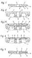
- the combustion chamber plate 2 shown in FIG. 1 has a circular, disc-shaped shape, in which a central, axially running passage 4 and grooves 5 on the combustion chamber side are arranged for the engagement of the workpiece holder of a friction welding machine.
- This special holder ensures the transmission of the torque required during friction welding, as well as the possibility of welding combustion chambers with a small cylinder spacing side by side.
- the thickness of the combustion chamber plate 2 is selected so that the grooves 5 are completely eliminated during the finishing of the cylinder head 1.
- the combustion chamber plate 2 is preferably made of a highly heat-resistant material, e.g. a suitable aluminum material. This material can be reinforced either continuously or as in Fig. 5 in a combustion chamber layer 6 by embedded fibers, preferably Al2O3 fibers.
- the coherent joining surface 7 of the combustion chamber plate 2 on the cylinder head side consists of a small, central, annular surface 8, which is enclosed by a surface 9 with a slightly conical or spherical shape, through which the thickness of the combustion chamber plate 2 tapers towards the edge, the outer end of which Surface can be formed as a transition radius 10.
- FIG. 2 shows the blank of the cylinder head housing 3, which is produced in a known manner from an aluminum material by casting, from which the flat bottom wall 11 on the combustion chamber side, a central opening 12 and the gas exchange channels 13 which end blindly at the transition into the bottom wall 11 are visible. These blind-ended gas exchange channels 13 result in a coherent joining surface 14 of the bottom wall 11.
- the joining surface 14 of the bottom wall 11 or both joining surfaces 7, 14 can likewise have a slightly conical or spherical shape.
- This design feature which is essential for the subsequent process of assembling, ensures that when the combustion chamber plate 2 is positioned in the correct position on the cylinder head housing 3 before the beginning of the joining process, only the small, central surface 8 rests directly against the combustion chamber-side joining surface 14 of the bottom wall 11 and, moreover, with increasing radial Distance from the central passage 4 or opening 12 there is a widening gap between the joining surfaces 7, 14 to be welded.
- the exemplary embodiment of the combustion chamber plate 2 is only suitable for an essentially flat or slightly curved shape of the combustion chamber 15. Further designs of a combustion chamber plate for deeper-curved combustion chambers are possible by incorporating a conical, conical or similar recess into the cylinder head housing and the joint surface on the cylinder head side of the combustion chamber plate being designed in accordance with the recess in the cylinder head housing. Regardless of the special shape of the combustion chamber, however, the design that is essential for the course of the friction welding process must be ensured with a small, central contact surface and, in addition, with a gap between the joining surfaces that becomes wider as the radial distance from the center increases.
- the prefabricated cylinder head housing 3 and the combustion chamber plate 2 are joined together in the manner according to the invention by friction welding, by means of a friction welding device, the circumferential combustion chamber plate 2 against the stationary cylinder head housing 3 is employed. Due to the design of the joining surfaces 7, 14, the heating or melting process begins first on the small, central surface 8 in the area of direct contact with the joining surfaces 7, 14 directly around the central opening 12 or bushing 4, which follows with increasing friction time continues outside.
- Part of the material melted during the welding process at the boundary layer between the parts to be welded flows in the course of the welding process, due to the contact pressure and the displacing effect of the slightly tapered or spherical joining surface 7 of the combustion chamber plate 2, from the inside to the outside, thereby forming the weld bead 16
- Another part of the melted material can also flow through or into the central opening 12 or passage 4.
- This melting and draining process of the material is continued until the joining surfaces 7, 14 are melted up to the edge zones of the parts to be welded. Due to the heating and melting from the inside out, a pore-free weld connection 17 is achieved over the entire joining surface 7.14, the torque required for the welding process being relatively small in relation to the size of the joining surfaces 7.14.
- the welding process is completed in a known manner by ending the rotary movement and pressing the parts to be welded together.
- the cylinder head 1 shown in FIG. 3 with the completed welded joint 17 can now be further processed using suitable processing methods.
- suitable processing methods for this purpose, starting from the combustion chamber 15, the connection to the blindly changing gas exchange channels 13 is produced and finished in accordance with FIG. 4, and the valve seats or the receptacle 18 for the valve seat rings are machined.
- the projection 19 of the combustion chamber plate 2 with the grooves 5 and the welding bead 16 processed, the combustion chamber 15 formed and the central opening 12 or bushing 4 drilled to receive a spark plug or an injection nozzle and finished.
Landscapes
- Engineering & Computer Science (AREA)
- Mechanical Engineering (AREA)
- General Engineering & Computer Science (AREA)
- Chemical & Material Sciences (AREA)
- Combustion & Propulsion (AREA)
- Cylinder Crankcases Of Internal Combustion Engines (AREA)
- Pressure Welding/Diffusion-Bonding (AREA)
Applications Claiming Priority (2)
| Application Number | Priority Date | Filing Date | Title |
|---|---|---|---|
| DE4124811A DE4124811C1 (enExample) | 1991-07-26 | 1991-07-26 | |
| DE4124811 | 1991-07-26 |
Publications (2)
| Publication Number | Publication Date |
|---|---|
| EP0525330A1 EP0525330A1 (de) | 1993-02-03 |
| EP0525330B1 true EP0525330B1 (de) | 1995-08-16 |
Family
ID=6437080
Family Applications (1)
| Application Number | Title | Priority Date | Filing Date |
|---|---|---|---|
| EP92109251A Expired - Lifetime EP0525330B1 (de) | 1991-07-26 | 1992-06-02 | Verfahren zur Herstellung eines Zylinderkopfes einer Brennkraftmaschine und Zylinderkopf |
Country Status (4)
| Country | Link |
|---|---|
| US (1) | US5215050A (enExample) |
| EP (1) | EP0525330B1 (enExample) |
| DE (1) | DE4124811C1 (enExample) |
| ES (1) | ES2077922T3 (enExample) |
Families Citing this family (11)
| Publication number | Priority date | Publication date | Assignee | Title |
|---|---|---|---|---|
| JPH0979014A (ja) * | 1995-09-14 | 1997-03-25 | Yamaha Motor Co Ltd | エンジン用シリンダヘッドの製造方法 |
| US5778531A (en) * | 1995-09-14 | 1998-07-14 | Yamaha Hatsudoki Kabushiki Kaisha | Method of manufacturing cylinder head for engine |
| DE10133757A1 (de) * | 2001-07-11 | 2003-02-13 | Mahle Ventiltrieb Gmbh | Einsatz als Bodenbereich eines Zylinderkopfes |
| US7854819B2 (en) * | 2005-05-17 | 2010-12-21 | Panasonic Corporation | Multilayer information recording medium and production method therefor |
| DE102005037735B4 (de) * | 2005-08-05 | 2010-07-01 | Nemak Linz Gmbh | Zylinderkopf-Gussrohteil, gegossener Zylinderkopf für Diesel-Verbrennungsmotoren und Verfahren zur Herstellung eines Zylinderkopf-Gussrohteils |
| DE102005059309A1 (de) * | 2005-12-09 | 2007-11-22 | Hydro Aluminium Mandl&Berger Gmbh | Aus mindestens zwei vorgegossenen Abschnitten zusammengesetztes Bauteil und Verfahren zu seiner Herstellung |
| US20080237304A1 (en) * | 2007-03-30 | 2008-10-02 | Caterpillar Inc. | Engine component having friction welded inserts |
| DE102008050195A1 (de) | 2008-10-01 | 2010-04-08 | Iav Gmbh Ingenieurgesellschaft Auto Und Verkehr | Zylinderkopf für Brennkraftmaschinen und Verfahren zur Herstellung eines Zylinderkopfs für eine Brennkraftmaschine |
| FR3039858A1 (fr) * | 2015-08-03 | 2017-02-10 | Saint Jean Ind | Culasse pour moteur a combustion interne, moteur comprenant une telle culasse et procede de fabrication d'une telle culasse |
| EP3374621B1 (en) | 2015-11-11 | 2020-10-28 | Ford Otomotiv Sanayi Anonim Sirketi | Multi-piece cylinder head |
| DE102016010020A1 (de) | 2016-08-13 | 2017-02-16 | Daimler Ag | Zylinderkopf für eine Verbrennungskraftmaschine eines Kraftwagens, sowie Verfahren zum Herstellen eines solchen Zylinderkopfes |
Citations (1)
| Publication number | Priority date | Publication date | Assignee | Title |
|---|---|---|---|---|
| DE1933520A1 (de) * | 1968-07-15 | 1970-08-27 | Wellworthy Ltd | Kolben und mehrere Verfahren zu ihrer Herstellung |
Family Cites Families (11)
| Publication number | Priority date | Publication date | Assignee | Title |
|---|---|---|---|---|
| US2730085A (en) * | 1950-12-19 | 1956-01-10 | Gen Motors Corp | Cylinder head |
| US2833264A (en) * | 1954-12-22 | 1958-05-06 | John Altorfer | Internal combustion engine |
| US3082752A (en) * | 1961-04-04 | 1963-03-26 | Reynolds Metals Co | Lined engine members and methods of making the same or the like |
| US4341826A (en) * | 1980-02-13 | 1982-07-27 | United Technologies Corporation | Internal combustion engine and composite parts formed from silicon carbide fiber-reinforced ceramic or glass matrices |
| DE3100755A1 (de) * | 1981-01-13 | 1982-09-02 | Klöckner-Humboldt-Deutz AG, 5000 Köln | Zylinderkopf fuer eine brennkraftmaschine |
| JPS60182339A (ja) * | 1984-02-29 | 1985-09-17 | Toyota Motor Corp | 軽金属製内燃機関用シリンダヘツド |
| US4774926A (en) * | 1987-02-13 | 1988-10-04 | Adams Ellsworth C | Shielded insulation for combustion chamber |
| JPH07111155B2 (ja) * | 1987-04-11 | 1995-11-29 | いすゞ自動車株式会社 | 断熱エンジン構造及びその製造方法 |
| JP2526947B2 (ja) * | 1987-12-14 | 1996-08-21 | いすゞ自動車株式会社 | 断熱エンジンの構造 |
| JPH0733766B2 (ja) * | 1988-08-30 | 1995-04-12 | トヨタ自動車株式会社 | 内燃機関の燃焼室 |
| US5111990A (en) * | 1988-12-20 | 1992-05-12 | United Technologies Corporation | Inertia weld notch control through the use of differential wall thicknesses |
-
1991
- 1991-07-26 DE DE4124811A patent/DE4124811C1/de not_active Expired - Lifetime
-
1992
- 1992-06-02 ES ES92109251T patent/ES2077922T3/es not_active Expired - Lifetime
- 1992-06-02 EP EP92109251A patent/EP0525330B1/de not_active Expired - Lifetime
- 1992-07-27 US US07/919,221 patent/US5215050A/en not_active Expired - Fee Related
Patent Citations (1)
| Publication number | Priority date | Publication date | Assignee | Title |
|---|---|---|---|---|
| DE1933520A1 (de) * | 1968-07-15 | 1970-08-27 | Wellworthy Ltd | Kolben und mehrere Verfahren zu ihrer Herstellung |
Non-Patent Citations (1)
| Title |
|---|
| DUBBEL Taschenbuch für den Maschinenbau, 14. Auflage, 1981, Seiten 345-350. * |
Also Published As
| Publication number | Publication date |
|---|---|
| ES2077922T3 (es) | 1995-12-01 |
| US5215050A (en) | 1993-06-01 |
| EP0525330A1 (de) | 1993-02-03 |
| DE4124811C1 (enExample) | 1992-08-06 |
Similar Documents
| Publication | Publication Date | Title |
|---|---|---|
| DE4218624C2 (de) | Mechanisches Element mit einer Welle, die sich unter Druck in mindestens ein zusammengesetztes Eingriffsbauteil eingepaßt ist sowie dessen Herstellungsverfahren | |
| DE68912496T2 (de) | Zylinderbuchse für eine Brennkraftmaschine. | |
| EP0525330B1 (de) | Verfahren zur Herstellung eines Zylinderkopfes einer Brennkraftmaschine und Zylinderkopf | |
| DE60122533T2 (de) | Kolben und verfahren zur herstellung | |
| DE60208827T2 (de) | Verbindungsstruktur eines Ventilsitzringes und dessen Herstellungsverfahren | |
| DE68919074T2 (de) | Maschinenkolbenzusammenbau und dessen geschmiedeter kolben mit kühlraum. | |
| DE4112889C2 (de) | Verfahren zur Herstellung eines Kolbenkopfes mit Kühlung für einen mehrteiligen, gegliederten Kolben für Verbrennungsmotore, sowie danach hergestellter Kolbenkopf | |
| DE3518721C2 (enExample) | ||
| DE1933520A1 (de) | Kolben und mehrere Verfahren zu ihrer Herstellung | |
| DE3521206C2 (enExample) | ||
| DE3907886A1 (de) | Verfahren zum herstellen einer nockenwelle | |
| DE3506069A1 (de) | Maschinenteil fuer eine brennkraftmaschine und verfahren zu dessen herstellung | |
| DE102011013067A1 (de) | Verfahren zur Herstellung eines Kolbens für einen Verbrennungsmotor | |
| DE4132295C2 (de) | Verfahren zur Herstellung eines zweiteiligen Kolbens und nach diesem Verfahren hergestellter Kolben | |
| EP1636474B1 (de) | Verfahren zur herstellung eines einteiligen kolbens für einen verbrennungsmotor | |
| DE3346056A1 (de) | Verfahren zum herstellen einer zusammengesetzten nockenwelle | |
| DE3611165C2 (enExample) | ||
| EP2603347B1 (de) | Kolben für einen verbrennungsmotor und verfahren zu seiner herstellung | |
| DE68914584T2 (de) | Aus Keramik und Metall zusammengesetzter Körper mit einer Reibschweissverbindung und mit einem keramischen Einsatz gegossener Kolben. | |
| EP1430211B1 (de) | Verfahren zur herstellung eines kolbens oder kolbenbodens für einen verbrennungsmotor | |
| EP0803037B1 (de) | Ventilgehäuse aus metall und kernform zu dessen herstellung | |
| EP0204121A1 (de) | Verfahren zur Herstellung eines thermisch und mechanisch hoch belastbaren sowie gegen Heisskorrosion geschützten Gaswechselventiles einer schwerölbetriebenen Brennkraftmaschine | |
| DE10311150A1 (de) | Verfahren zur Herstellung eines geschmiedeten Kolbens für einen Verbrennungsmotor | |
| DE102005021428A1 (de) | Verfahren zur Herstellung eines geschmiedeten Kolbens | |
| DE3214093A1 (de) | Kolben fuer verbrennungskraftmaschinen mit einem seine brennraumnahen wandteile abdeckenden einsatz |
Legal Events
| Date | Code | Title | Description |
|---|---|---|---|
| PUAI | Public reference made under article 153(3) epc to a published international application that has entered the european phase |
Free format text: ORIGINAL CODE: 0009012 |
|
| 17P | Request for examination filed |
Effective date: 19921109 |
|
| AK | Designated contracting states |
Kind code of ref document: A1 Designated state(s): ES FR GB IT |
|
| 17Q | First examination report despatched |
Effective date: 19940429 |
|
| GRAA | (expected) grant |
Free format text: ORIGINAL CODE: 0009210 |
|
| ITF | It: translation for a ep patent filed | ||
| AK | Designated contracting states |
Kind code of ref document: B1 Designated state(s): ES FR GB IT |
|
| GBT | Gb: translation of ep patent filed (gb section 77(6)(a)/1977) |
Effective date: 19950821 |
|
| ET | Fr: translation filed | ||
| REG | Reference to a national code |
Ref country code: ES Ref legal event code: FG2A Ref document number: 2077922 Country of ref document: ES Kind code of ref document: T3 |
|
| PLBE | No opposition filed within time limit |
Free format text: ORIGINAL CODE: 0009261 |
|
| STAA | Information on the status of an ep patent application or granted ep patent |
Free format text: STATUS: NO OPPOSITION FILED WITHIN TIME LIMIT |
|
| 26N | No opposition filed | ||
| REG | Reference to a national code |
Ref country code: FR Ref legal event code: TP |
|
| REG | Reference to a national code |
Ref country code: GB Ref legal event code: 732E |
|
| REG | Reference to a national code |
Ref country code: GB Ref legal event code: 732E |
|
| PGFP | Annual fee paid to national office [announced via postgrant information from national office to epo] |
Ref country code: GB Payment date: 20010515 Year of fee payment: 10 |
|
| PGFP | Annual fee paid to national office [announced via postgrant information from national office to epo] |
Ref country code: FR Payment date: 20010531 Year of fee payment: 10 |
|
| PGFP | Annual fee paid to national office [announced via postgrant information from national office to epo] |
Ref country code: ES Payment date: 20010614 Year of fee payment: 10 |
|
| REG | Reference to a national code |
Ref country code: GB Ref legal event code: IF02 |
|
| PG25 | Lapsed in a contracting state [announced via postgrant information from national office to epo] |
Ref country code: GB Free format text: LAPSE BECAUSE OF NON-PAYMENT OF DUE FEES Effective date: 20020602 |
|
| PG25 | Lapsed in a contracting state [announced via postgrant information from national office to epo] |
Ref country code: ES Free format text: LAPSE BECAUSE OF NON-PAYMENT OF DUE FEES Effective date: 20020603 |
|
| GBPC | Gb: european patent ceased through non-payment of renewal fee |
Effective date: 20020602 |
|
| PG25 | Lapsed in a contracting state [announced via postgrant information from national office to epo] |
Ref country code: FR Free format text: LAPSE BECAUSE OF NON-PAYMENT OF DUE FEES Effective date: 20030228 |
|
| REG | Reference to a national code |
Ref country code: FR Ref legal event code: ST |
|
| REG | Reference to a national code |
Ref country code: ES Ref legal event code: FD2A Effective date: 20030711 |
|
| PG25 | Lapsed in a contracting state [announced via postgrant information from national office to epo] |
Ref country code: IT Free format text: LAPSE BECAUSE OF NON-PAYMENT OF DUE FEES;WARNING: LAPSES OF ITALIAN PATENTS WITH EFFECTIVE DATE BEFORE 2007 MAY HAVE OCCURRED AT ANY TIME BEFORE 2007. THE CORRECT EFFECTIVE DATE MAY BE DIFFERENT FROM THE ONE RECORDED. Effective date: 20050602 |