EP0524562A1 - A tread for a tire - Google Patents
A tread for a tire Download PDFInfo
- Publication number
- EP0524562A1 EP0524562A1 EP92112312A EP92112312A EP0524562A1 EP 0524562 A1 EP0524562 A1 EP 0524562A1 EP 92112312 A EP92112312 A EP 92112312A EP 92112312 A EP92112312 A EP 92112312A EP 0524562 A1 EP0524562 A1 EP 0524562A1
- Authority
- EP
- European Patent Office
- Prior art keywords
- tread
- groove
- walls
- wall
- grooves
- Prior art date
- Legal status (The legal status is an assumption and is not a legal conclusion. Google has not performed a legal analysis and makes no representation as to the accuracy of the status listed.)
- Granted
Links
Images


Classifications
-
- B—PERFORMING OPERATIONS; TRANSPORTING
- B60—VEHICLES IN GENERAL
- B60C—VEHICLE TYRES; TYRE INFLATION; TYRE CHANGING; CONNECTING VALVES TO INFLATABLE ELASTIC BODIES IN GENERAL; DEVICES OR ARRANGEMENTS RELATED TO TYRES
- B60C11/00—Tyre tread bands; Tread patterns; Anti-skid inserts
- B60C11/03—Tread patterns
- B60C11/04—Tread patterns in which the raised area of the pattern consists only of continuous circumferential ribs, e.g. zig-zag
- B60C11/042—Tread patterns in which the raised area of the pattern consists only of continuous circumferential ribs, e.g. zig-zag further characterised by the groove cross-section
-
- B—PERFORMING OPERATIONS; TRANSPORTING
- B60—VEHICLES IN GENERAL
- B60C—VEHICLE TYRES; TYRE INFLATION; TYRE CHANGING; CONNECTING VALVES TO INFLATABLE ELASTIC BODIES IN GENERAL; DEVICES OR ARRANGEMENTS RELATED TO TYRES
- B60C11/00—Tyre tread bands; Tread patterns; Anti-skid inserts
- B60C11/03—Tread patterns
- B60C11/0304—Asymmetric patterns
-
- B—PERFORMING OPERATIONS; TRANSPORTING
- B60—VEHICLES IN GENERAL
- B60C—VEHICLE TYRES; TYRE INFLATION; TYRE CHANGING; CONNECTING VALVES TO INFLATABLE ELASTIC BODIES IN GENERAL; DEVICES OR ARRANGEMENTS RELATED TO TYRES
- B60C11/00—Tyre tread bands; Tread patterns; Anti-skid inserts
- B60C11/03—Tread patterns
- B60C11/0306—Patterns comprising block rows or discontinuous ribs
- B60C11/0309—Patterns comprising block rows or discontinuous ribs further characterised by the groove cross-section
-
- B—PERFORMING OPERATIONS; TRANSPORTING
- B60—VEHICLES IN GENERAL
- B60C—VEHICLE TYRES; TYRE INFLATION; TYRE CHANGING; CONNECTING VALVES TO INFLATABLE ELASTIC BODIES IN GENERAL; DEVICES OR ARRANGEMENTS RELATED TO TYRES
- B60C11/00—Tyre tread bands; Tread patterns; Anti-skid inserts
- B60C11/03—Tread patterns
- B60C11/0327—Tread patterns characterised by special properties of the tread pattern
- B60C11/033—Tread patterns characterised by special properties of the tread pattern by the void or net-to-gross ratios of the patterns
-
- B—PERFORMING OPERATIONS; TRANSPORTING
- B60—VEHICLES IN GENERAL
- B60C—VEHICLE TYRES; TYRE INFLATION; TYRE CHANGING; CONNECTING VALVES TO INFLATABLE ELASTIC BODIES IN GENERAL; DEVICES OR ARRANGEMENTS RELATED TO TYRES
- B60C11/00—Tyre tread bands; Tread patterns; Anti-skid inserts
- B60C11/03—Tread patterns
- B60C11/11—Tread patterns in which the raised area of the pattern consists only of isolated elements, e.g. blocks
Definitions
- the invention relates to a tread for a pneumatic tire.
- the tread is particularly well suited for high performance tires.
- ground or road contacting elements in the form of ribs or blocks.
- the ribs or blocks are spaced by non-road contacting grooves.
- the grooves are channels or voids which allow water to be moved into them so that the ground contacting surfaces can maintain good traction.
- the tread under wet conditions would lose ground contact, a thin layer or film of water would be between the tire and the road and a phenomena called hydroplaning would result. Under severe hydroplaning conditions the tire loses traction and control of the vehicle can be lost.
- the design of a tire tread is a compromise. Under dry conditions the maximum amount of tread contacting the road is optimum. For example, the tire treads used at the Indianapolis 500 race are smooth and 100% of the tread while in the footprint of the tire contacts the road. In the event of rain the race stops.
- the tread As one is required to drive under less than ideal dry conditions a tread with 100% ground contact is not practical.
- the tread is therefore provided with grooves to accommodate wet or snowy road conditions.
- the ratio of areas of ground contacting elements to voids within the area of road contact, otherwise known in the tire art as the "footprint" is relatively high, generally in the 60% to 75% range. This high net-to-gross ratio enables the tire to be designed with minimal noise and vibration characteristics.
- the weight of the vehicle shifts loading the outer set of tires while reducing the load on the inner set of tires.
- the tires deflect such that the outer shoulder area of the tread is in ground contact on the outer set of tires while the inner shoulder area of the lighter loaded inner set of tires is in ground contact.
- the resultant lateral loads must be absorbed by these ground contacting elements. It is desirable therefore that the ground contacting ribs or block elements be laterally stiff in order to absorb the lateral forces generated by the cornering vehicle.
- the present invention describes a tread having improved lateral stiffness and superior high speed cornering.
- a tread for a pneumatic tire when angularly configured comprises an axis, first and second lateral edges, a tread surface and a plurality of circumferential grooves in the tread.
- the circumferential grooves define rib or block tread elements.
- the grooves have first and second walls. The first walls are on the side of the groove in a first axial direction and the second walls are on the opposite side of the groove.
- the respective groove walls have an angular orientation relative to a line perpendicular to a tangent to the tread surface curvature as approximately defined at the center of the groove.
- the first and second walls have angular variation wherein the first walls of the grooves have an angular orientation greater than that of the second wall as a function of axial distance from the first lateral edge of the tread.
- the angular variation changes wherein the second wall has an angular orientation equal to or greater than the orientation of the first wall at the intermediate groove and at any circumferential groove or grooves positioned between the second lateral edge and the intermediate groove.
- “Circumferential” means lines or directions extending along the perimeter of the surface of the annular tread perpendicular to the axial direction.
- Ring and radially are used to mean directions radially toward or away from the axis of rotation of the tire.
- “Lateral” means an axial direction.
- Compensated Tread Width means the tread width multiplied by the aspect ratio.
- Aspect Ratio of a tire means the ratio of the section height to the section width.
- “Footprint” means the contact patch or area of contact of the tire tread with a flat surface at zero speed and under normal load and pressure, including the area occupied by grooves as well as the tread elements.
- Net-to-gross means the total area of ground contacting tread elements with the footprint divided by the gross area of the footprint.
- “Groove” means an elongated void area in a tread that may extend circumferentially or laterally about the tread in a straight, curved, or zig-zag manner. Circumferentially and laterally extending grooves sometimes have common portions and may be subclassified as “wide”, “narrow”, or “slot”.
- the slot typically is formed by steel blades inserted into a cast or machined mold or tread ring therefor. In the appended drawings, slots are illustrated by single lines because they are so narrow.
- a “slot” is a groove having a width in the range from about 0.2% to 0.3% of the compensated tread width, whereas a wide groove has a width (W) greater than 2% of the compensated tread width, an intermediate width groove has a width 1/3 to 3/4 W, and a narrow groove has a width of 1/10 to 1/3 W.
- the "groove width” is equal to tread surface area occupied by a groove or groove portion, the width of which is in question, divided by the length of such groove or groove portion; thus, the groove width is its average width over its length. Grooves, as well as other voids, reduce the stiffness of the tread regions in which they are located. Slots often are used for this purpose, as are laterally extending narrow or wide grooves.
- Grooves may be of varying depths in a tire.
- the depth of a groove may vary around the circumference of the tread, or the depth of one groove may be constant but vary from the depth of another groove in the tire. If such narrow or wide grooves are of substantially reduced depth as compared to wide circumferential grooves which they interconnect, they are regarded as forming "tie bars" tending to maintain a rib-like character in the tread region involved.
- “Sipe” means small slots molded into the tread elements of a tire that subdivide the tread surface and improve traction.
- Outside Shoulder means the shoulder farthest away from the vehicle.
- Ring means a circumferentially extending strip of rubber on the tread which is defined by at least one circumferential groove and either a second such groove or a lateral edge, the strip being laterally undivided by full-depth grooves.
- Thread Element means a rib or a block element.
- Equatorial plane means the plane perpendicular to the tire's axis of rotation and passing through the center of its tread.
- Fig. 1 is a perspective view of the tread of the present invention attached to a tire.
- Fig. 2 is a plan view of the tread of Fig. 1.
- Fig. 3 is an cross-sectional view of the tire and tread as illustrated in Fig. 2 taken along line 3-3.
- Fig. 4 is an enlarged a portion of the tread cross section as illustrated in Fig. 3.
- Fig. 4 depicts the angular orientation of the first and second groove walls.
- Fig. 5A and 5B illustrate the effective contact patch of a set of tires having the tread illustrated in Figures 1-4;
- Fig. 5A represents a vehicle traveling in a straight line and
- Fig. 5B represents a vehicle making a left turning maneuver.
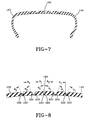
- Fig. 7 is a cross-sectional view of the tread of Fig. 6 taken along lines 7-7.
- Fig. 8 is a portion of the tread cross-section illustrated in Fig. 7.
- Fig. 8 depicts the angular orientation of the first and second groove walls.
- a tread 12 according to the present invention is illustrated attached to a pneumatic tire 10.
- the tread when angularly configured as illustrated has an axis R, first and second lateral edges 14 and 16, a plurality of tread elements 50 with a tread surface 52 and a plurality of circumferential grooves 15, 18 and 19, and lateral grooves 17A and 17B.
- the grooves define rib or block tread elements 50. All circumferential grooves have first and second walls 20 and 22 respectively as shown in Fig. 4. The first walls 20 are on the side of the groove in a first axial direction and the second walls 22 are on the opposite side of the groove.
- the respective groove walls have an angular orientation 01, 02 relative to a line perpendicular to a tangent to the tread surface curvature as approximately defined at the center of the groove.
- 01 is the angular orientation of the first wall
- 02 is the angular orientation of the second wall.
- the first and second walls have an angular variation wherein the first walls of the grooves have an angular orientation ⁇ 1 greater than the angular orientation ⁇ 2 of the second wall as a function of axial distance from the first lateral edge. That is ⁇ 1 ⁇ 2 for each groove between the first lateral edge 14 and the intermediate groove 18.
- the angular variation changes wherein the second wall 22 has an angular orientation equal to or greater than the orientation of the first wall 20 at the intermediate groove 18 and at any circumferential groove or grooves position between the second lateral edge 16 and the intermediate groove 18.
- the tread 12 as illustrated in Fig. 1 through Fig. 4 is asymmetrical and directional.
- the tread pattern is designed with a wide circumferential groove 18 located in proximity to the second lateral edge 16 and not centered at the equatorial plane of the tread.
- the illustrated tread 12 is also directional in that the tire 10 has a preferred forward travel direction. This pattern means that a set of tires includes a pair of left side and a pair of right side tires for a vehicle.
- the first lateral edge 14 is located at the outboard side of the tire and the second lateral edge 16 is located of the inboard side of the tire.
- the illustrated tread 12 is the subject of a co-pending patent application serial number 07/736,182, the description of the tread being incorporated by reference.
- the above described tread 12 also has a unique configuration of lateral grooves 17A and 17B at the tread shoulders.
- the lateral grooves 17 have leading and trailing edge surfaces 30, 40.
- the trailing edge surfaces 40 have a negative angular orientation.
- the description of the lateral grooves are described in detail in a co-pending patent application serial number 07/736,189 which is hereby incorporated by reference.
- the tread 12 as illustrated incorporates two independent pitches.
- the pitches differing in number, lengths, and orientation.
- the detailed description of the pitching is described in co-pending patent application serial number 07/736,192 which is hereby incorporated by reference.
- the tread 12 as described above with a changing angular variation of the circumferential groove walls, permits an increase in lateral stiffness to be accomplished without sacrificing the ground contacting surface area of the tread elements.
- the first lateral edge 14 would be located at the outside position relative to a vehicle while the second lateral edge 16 would be at the inside position relative to a vehicle.
- the angle ⁇ 1 of the first wall 20 is greater than the angle ⁇ 2 of the second wall 22 for the circumferential grooves located between the first lateral edge 14 and the intermediate groove 18.
- the angle ⁇ 1 in the region between the intermediate groove 18 and the first lateral edge 14, has an angle of inclination relative to a plane perpendicular to a tangent to the tread surface.
- the inclination ⁇ 1 slopes the first wall as illustrated in Figs. 2 through 4.
- the first wall being sloped reinforces the adjacent tread element against lateral forces. This stiffens the tread element and improves the cornering capability of the tire.
- the second wall has an angular orientation ⁇ 2 opposite to and less in magnitude than ⁇ 1. This ensures that the ground contact area remains large while at the same time the groove void area is not reduced as compared to conventional grooves having equal angled groove walls.
- Fig. 5A shows a set of tires and their respective footprints in all four wheel positions traveling in a straight line. The tires are normally loaded and inflated.
- Fig. 5b illustrate the theoretical shift in effective footprint as the vehicle turns.
- the vehicle relies primarily on the outer tires to resist a majority of the lateral forces.
- the angular variation changes such that ⁇ 2 is equal to or greater than ⁇ 1 in magnitude.
- the second wall 22 is either equally or greater reinforced than the first wall 20.
- intermediate groove 18 is positioned between the equatorial plane and the second lateral edge 16.
- the intermediate groove 180 may be centered.
- a symmetrical tread pattern as illustrated would permit the tire to be produced with a non-directional tread pattern.
- the groove walls preferably would be angularly inclined such that the inboard side grooves would be similar but oppositely inclined relative to the outboard side grooves. The directions of travel would thus not effect the reinforcing at the lateral edges.
- the change in angular variation would occur at the centered intermediate groove 180.
- the tread as illustrated in Figs 1 through 4, has six circumferential grooves. Starting from the outside shoulder or first lateral edge and progressing axially inwardly, the tread has a first narrow circumferential groove 19 with a first wall 20 inclined at 6° a second wall 22 at ⁇ °; a second narrow circumferential groove 19 with a first wall 20 inclined at 6° and a second wall 22 at ⁇ °; a first intermediate width groove 15 with a first wall 20 at 20° incline and a second wall 22 at ⁇ ° incline; a second intermediate width groove with a first wall 20 inclined at 20° and a second wall 22 at ⁇ °; a wide intermediate groove 18 wherein the angular orientation changes, the intermediate groove 18 having first and second walls 20, 22 equally but oppositely inclined at 12°; and a third intermediate width groove 15 having a first wall 20 at ⁇ ° and a second wall 22 at 20°, the third intermediate width groove being between the intermediate groove 18 and the inside shoulder or second lateral edge 16.
- the angular variation ranges from 6° to 20° in the preferred embodiment. The higher the angle the greater the lateral stiffness of the tread element adjacent the inclined wall.
- the outside two narrow circumferential grooves are designed with a 6° inclination at the first wall and 0° at the second wall. In sharp cornering high lateral forces are exerted on the tread elements, adjacent these grooves. The narrow grooves are allowed to actually close. The groove void is thus occupied by the laterally outer adjacent tread element. This element contacts the laterally inner adjacent tread element, resulting in a cooperative stiffening of the tread laterally. This in combination with the angularly variant groove walls enhances lateral stiffness.
- intermediate width grooves 15 located between first lateral edge 14 and the wide intermediate groove 18 are angularly braced at higher angles of inclination at the first wall.
- the included angle between the first and second groove wall, ⁇ 1 + ⁇ 2 should be below 30°, preferably below 25°. This insures that the ground contact area remains large.
- the three intermediate width grooves each have a combined ⁇ 1 + ⁇ 2 of 20°
- the wide intermediate groove 18 has a combined included angle of 24°
- the two narrow grooves each have a combined included angle ⁇ 1 + ⁇ 2 of 6°.
- the tread in the best mode of practicing the invention includes the utilization of crowned block elements.
- the description of such elements is to be found in U. S. Patent 4,722,738 and is incorporated herein by reference.
- Treads have been constructed and tested with crowned elements and without such crowned elements. Improvements in lateral cornering forces have been observed in both tread versions when compared to tires with a conventional tread design with equal angled circumferential grooves.
- Steering response is the subjective measure on a scale of 1-10 of a tire's ability to change direction.
- test tire had a faster lap time of 50.59 second versus 50.70 seconds for the control tires on a wet test track using the same vehicle.
- test tire ran a time of 1.22.71, compared to a time of 1:23.05 for the control tire, or a 0.31 sec. per lap improvement. According to the driver the tires subjectively felt about the same.
- the cornering coefficient at a 1.0° slip angle was improved 1.2%.
- the conventional tire rated 0.3722 versus the angled grooves rating of 0.3766.
- the cornering coefficient measures the lateral force divided by the normal force and is a indication of the tires ability to make high speed turns.
- the overall data of the test tires when compared to the commercially available Goodyear Eagle® ZR50 tires shows an improvement in cornering capability when the ZR50 tire is produced with the circumferential grooves angled as described according to the present invention.
- the improvement is particularly significant when one considers that the standard Eagle ZR50 tire is a high performance tire exhibiting excellent handling characteristics.
- the intermediate groove can have angle ⁇ 2 greater than or equal to ⁇ 1.
- the preferred tread has wide, intermediate width, and narrow circumferential grooves, benefits of the invention can be obtained with other configurations of the circumferential grooves. Also, variations in groove shape or construction can be employed.
- the circumferential grooves may be straight, zig-zag or sinusoidal.
- the tread may or may not also employ lateral grooves, to form block elements in the tread.
Abstract
Description
- The invention relates to a tread for a pneumatic tire. The tread is particularly well suited for high performance tires.
- In the conventional design of a tread for a pneumatic tire there are provided ground or road contacting elements in the form of ribs or blocks. The ribs or blocks are spaced by non-road contacting grooves. The grooves are channels or voids which allow water to be moved into them so that the ground contacting surfaces can maintain good traction. In the absence of grooves, the tread under wet conditions would lose ground contact, a thin layer or film of water would be between the tire and the road and a phenomena called hydroplaning would result. Under severe hydroplaning conditions the tire loses traction and control of the vehicle can be lost.
- The design of a tire tread is a compromise. Under dry conditions the maximum amount of tread contacting the road is optimum. For example, the tire treads used at the Indianapolis 500 race are smooth and 100% of the tread while in the footprint of the tire contacts the road. In the event of rain the race stops.
- As one is required to drive under less than ideal dry conditions a tread with 100% ground contact is not practical. The tread is therefore provided with grooves to accommodate wet or snowy road conditions. In passenger tires, the ratio of areas of ground contacting elements to voids within the area of road contact, otherwise known in the tire art as the "footprint", is relatively high, generally in the 60% to 75% range. This high net-to-gross ratio enables the tire to be designed with minimal noise and vibration characteristics.
- To design a tire with a high net-to-gross ratio yet good traction under wet conditions requires a tremendous amount of skill. The conflicting nature of the design requirements requires a fine balance in selecting the appropriate features for a successful tire tread design.
- In high speed and high performance tires the performance of the vehicle is generally limited to the ability of the tires to respond.
- This is particularly true in high speed cornering.
- As a vehicle enters a turn the weight of the vehicle shifts loading the outer set of tires while reducing the load on the inner set of tires. The tires deflect such that the outer shoulder area of the tread is in ground contact on the outer set of tires while the inner shoulder area of the lighter loaded inner set of tires is in ground contact. The resultant lateral loads must be absorbed by these ground contacting elements. It is desirable therefore that the ground contacting ribs or block elements be laterally stiff in order to absorb the lateral forces generated by the cornering vehicle.
- The present invention describes a tread having improved lateral stiffness and superior high speed cornering.
- A tread for a pneumatic tire is described, the tread when angularly configured comprises an axis, first and second lateral edges, a tread surface and a plurality of circumferential grooves in the tread. The circumferential grooves define rib or block tread elements. The grooves have first and second walls. The first walls are on the side of the groove in a first axial direction and the second walls are on the opposite side of the groove. The respective groove walls have an angular orientation relative to a line perpendicular to a tangent to the tread surface curvature as approximately defined at the center of the groove.
- The first and second walls have angular variation wherein the first walls of the grooves have an angular orientation greater than that of the second wall as a function of axial distance from the first lateral edge of the tread. At a groove intermediate the first and second lateral edges the angular variation changes wherein the second wall has an angular orientation equal to or greater than the orientation of the first wall at the intermediate groove and at any circumferential groove or grooves positioned between the second lateral edge and the intermediate groove.
- "Axial" and "axially" are used herein to refer to lines or directions that are parallel to the axis of rotation of the tire.
- "Circumferential" means lines or directions extending along the perimeter of the surface of the annular tread perpendicular to the axial direction.
- "Radial" and "radially" are used to mean directions radially toward or away from the axis of rotation of the tire.
- "Lateral" means an axial direction.
- "Compensated Tread Width" means the tread width multiplied by the aspect ratio.
- "Aspect Ratio" of a tire means the ratio of the section height to the section width.
- "Footprint" means the contact patch or area of contact of the tire tread with a flat surface at zero speed and under normal load and pressure, including the area occupied by grooves as well as the tread elements.
- "Net-to-gross" means the total area of ground contacting tread elements with the footprint divided by the gross area of the footprint.
- "Groove" means an elongated void area in a tread that may extend circumferentially or laterally about the tread in a straight, curved, or zig-zag manner. Circumferentially and laterally extending grooves sometimes have common portions and may be subclassified as "wide", "narrow", or "slot". The slot typically is formed by steel blades inserted into a cast or machined mold or tread ring therefor. In the appended drawings, slots are illustrated by single lines because they are so narrow. A "slot" is a groove having a width in the range from about 0.2% to 0.3% of the compensated tread width, whereas a wide groove has a width (W) greater than 2% of the compensated tread width, an intermediate width groove has a
width 1/3 to 3/4 W, and a narrow groove has a width of 1/10 to 1/3 W. The "groove width" is equal to tread surface area occupied by a groove or groove portion, the width of which is in question, divided by the length of such groove or groove portion; thus, the groove width is its average width over its length. Grooves, as well as other voids, reduce the stiffness of the tread regions in which they are located. Slots often are used for this purpose, as are laterally extending narrow or wide grooves. Grooves may be of varying depths in a tire. The depth of a groove may vary around the circumference of the tread, or the depth of one groove may be constant but vary from the depth of another groove in the tire. If such narrow or wide grooves are of substantially reduced depth as compared to wide circumferential grooves which they interconnect, they are regarded as forming "tie bars" tending to maintain a rib-like character in the tread region involved. - "Sipe" means small slots molded into the tread elements of a tire that subdivide the tread surface and improve traction.
- "Inside Shoulder" means the shoulder nearest the vehicle.
- "Outside Shoulder" means the shoulder farthest away from the vehicle.
- "Rib" means a circumferentially extending strip of rubber on the tread which is defined by at least one circumferential groove and either a second such groove or a lateral edge, the strip being laterally undivided by full-depth grooves.
- "Tread Element" means a rib or a block element.
- "Equatorial plane (EP)" means the plane perpendicular to the tire's axis of rotation and passing through the center of its tread.
- Fig. 1 is a perspective view of the tread of the present invention attached to a tire.
- Fig. 2 is a plan view of the tread of Fig. 1.
- Fig. 3 is an cross-sectional view of the tire and tread as illustrated in Fig. 2 taken along line 3-3.
- Fig. 4 is an enlarged a portion of the tread cross section as illustrated in Fig. 3. Fig. 4 depicts the angular orientation of the first and second groove walls.
- Fig. 5A and 5B illustrate the effective contact patch of a set of tires having the tread illustrated in Figures 1-4; Fig. 5A represents a vehicle traveling in a straight line and Fig. 5B represents a vehicle making a left turning maneuver.
- Fig. 6 in an alternate embodiment of the tread.
- Fig. 7 is a cross-sectional view of the tread of Fig. 6 taken along lines 7-7.
- Fig. 8 is a portion of the tread cross-section illustrated in Fig. 7. Fig. 8 depicts the angular orientation of the first and second groove walls.
- In Fig. 1, a
tread 12 according to the present invention is illustrated attached to apneumatic tire 10. The tread when angularly configured as illustrated has an axis R, first and second lateral edges 14 and 16, a plurality oftread elements 50 with atread surface 52 and a plurality ofcircumferential grooves lateral grooves - As illustrated in Figs. 1 through 4 the grooves define rib or block
tread elements 50. All circumferential grooves have first andsecond walls first walls 20 are on the side of the groove in a first axial direction and thesecond walls 22 are on the opposite side of the groove. - The respective groove walls have an
angular orientation lateral edge 14 and theintermediate groove 18. - At the
groove 18 intermediate the first and second lateral edges 14, 16 the angular variation changes wherein thesecond wall 22 has an angular orientation equal to or greater than the orientation of thefirst wall 20 at theintermediate groove 18 and at any circumferential groove or grooves position between the secondlateral edge 16 and theintermediate groove 18. - In the preferred embodiment of the invention the
tread 12 as illustrated in Fig. 1 through Fig. 4 is asymmetrical and directional. The tread pattern is designed with a widecircumferential groove 18 located in proximity to the secondlateral edge 16 and not centered at the equatorial plane of the tread. The illustratedtread 12 is also directional in that thetire 10 has a preferred forward travel direction. This pattern means that a set of tires includes a pair of left side and a pair of right side tires for a vehicle. - The first
lateral edge 14 is located at the outboard side of the tire and the secondlateral edge 16 is located of the inboard side of the tire. - The illustrated
tread 12 is the subject of a co-pending patent application serial number 07/736,182, the description of the tread being incorporated by reference. - The above described
tread 12 also has a unique configuration oflateral grooves - The
tread 12 as illustrated incorporates two independent pitches. The pitches differing in number, lengths, and orientation. The detailed description of the pitching is described in co-pending patent application serial number 07/736,192 which is hereby incorporated by reference. - The
tread 12, as described above with a changing angular variation of the circumferential groove walls, permits an increase in lateral stiffness to be accomplished without sacrificing the ground contacting surface area of the tread elements. - As illustrated in Figs. 1 through 4 the first
lateral edge 14 would be located at the outside position relative to a vehicle while the secondlateral edge 16 would be at the inside position relative to a vehicle. The angle ϑ₁ of thefirst wall 20 is greater than the angle ϑ₂ of thesecond wall 22 for the circumferential grooves located between the firstlateral edge 14 and theintermediate groove 18. - The angle ϑ₁, in the region between the
intermediate groove 18 and the firstlateral edge 14, has an angle of inclination relative to a plane perpendicular to a tangent to the tread surface. - The inclination ϑ₁ slopes the first wall as illustrated in Figs. 2 through 4. The first wall being sloped reinforces the adjacent tread element against lateral forces. This stiffens the tread element and improves the cornering capability of the tire. The second wall has an angular orientation ϑ₂ opposite to and less in magnitude than ϑ₁. This ensures that the ground contact area remains large while at the same time the groove void area is not reduced as compared to conventional grooves having equal angled groove walls.
- In prior art tires the walls of the circumferential grooves are inclined oppositely in orientation yet equally in magnitude. That is ϑ₁ equals ϑ₂.
- By using the angular variation discussed above an increase in lateral stiffness is achieved without sacrificing or reducing the circumferential groove void area or the ground contact surface area across the tread laterally. The large ϑ₁ angle relative to 0₂ for grooves located between the first
lateral edge 14 and theintermediate groove 18 in effect braces the tread element at thefirst walls 20. - The tires when mounted on a vehicle will respond to a turn whereby the outside tires absorb a majority of the vehicle weight. The outside tires will resist the lateral forces primarily at the outside shoulder region of the tire as illustrated by Fig. 5b. Fig. 5A shows a set of tires and their respective footprints in all four wheel positions traveling in a straight line. The tires are normally loaded and inflated. Fig. 5b illustrate the theoretical shift in effective footprint as the vehicle turns.
- The vehicle relies primarily on the outer tires to resist a majority of the lateral forces.
- At the
intermediate groove 18 the angular variation changes such that ϑ₂ is equal to or greater than ϑ₁ in magnitude. At this region, thesecond wall 22 is either equally or greater reinforced than thefirst wall 20. - In the preferred embodiment the
intermediate groove 18 is positioned between the equatorial plane and the secondlateral edge 16. - As illustrated in Figs. 6, 7, and 8 the
intermediate groove 180 may be centered. A symmetrical tread pattern as illustrated would permit the tire to be produced with a non-directional tread pattern. The groove walls preferably would be angularly inclined such that the inboard side grooves would be similar but oppositely inclined relative to the outboard side grooves. The directions of travel would thus not effect the reinforcing at the lateral edges. The change in angular variation would occur at the centeredintermediate groove 180. - In the preferred embodiment, the tread, as illustrated in Figs 1 through 4, has six circumferential grooves. Starting from the outside shoulder or first lateral edge and progressing axially inwardly, the tread has a first narrow
circumferential groove 19 with afirst wall 20 inclined at 6° asecond wall 22 at ϑ°; a second narrowcircumferential groove 19 with afirst wall 20 inclined at 6° and asecond wall 22 at ϑ°; a firstintermediate width groove 15 with afirst wall 20 at 20° incline and asecond wall 22 at ϑ° incline; a second intermediate width groove with afirst wall 20 inclined at 20° and asecond wall 22 at ϑ°; a wideintermediate groove 18 wherein the angular orientation changes, theintermediate groove 18 having first andsecond walls intermediate width groove 15 having afirst wall 20 at ϑ° and asecond wall 22 at 20°, the third intermediate width groove being between theintermediate groove 18 and the inside shoulder or secondlateral edge 16. - The angular variation ranges from 6° to 20° in the preferred embodiment. The higher the angle the greater the lateral stiffness of the tread element adjacent the inclined wall.
- The outside two narrow circumferential grooves are designed with a 6° inclination at the first wall and 0° at the second wall. In sharp cornering high lateral forces are exerted on the tread elements, adjacent these grooves. The narrow grooves are allowed to actually close. The groove void is thus occupied by the laterally outer adjacent tread element. This element contacts the laterally inner adjacent tread element, resulting in a cooperative stiffening of the tread laterally. This in combination with the angularly variant groove walls enhances lateral stiffness.
- The
intermediate width grooves 15 located between firstlateral edge 14 and the wideintermediate groove 18 are angularly braced at higher angles of inclination at the first wall. - It is believed that the included angle between the first and second groove wall, ϑ₁ + ϑ₂ should be below 30°, preferably below 25°. This insures that the ground contact area remains large. In the illustrated preferred embodiment of Figs. 1 through 4 the three intermediate width grooves each have a combined ϑ₁ + ϑ₂ of 20°, the wide
intermediate groove 18 has a combined included angle of 24°, and the two narrow grooves each have a combined included angle ϑ₁ + ϑ₂ of 6°. - The above combination of angular orientation of groove walls maximizes the amount of ground contact in an axial direction while still providing several large water evacuating grooves.
- The tread in the best mode of practicing the invention includes the utilization of crowned block elements. The description of such elements is to be found in U. S. Patent 4,722,738 and is incorporated herein by reference. Treads have been constructed and tested with crowned elements and without such crowned elements. Improvements in lateral cornering forces have been observed in both tread versions when compared to tires with a conventional tread design with equal angled circumferential grooves.
- In one such series of experimental tests, Goodyear Eagle® "Gatorback" ZR50 tires were constructed with circumferential grooves angled according to the present invention without crowned elements. As a control conventional Goodyear Eagle® "Gatorback" ZR50 tires having circumferential groove with conventional angled walls, the first wall equal to the second wall, were tested. All tires were of a P245/50ZR16 size.
- In terms of subjective handling the conventional tires rated 7.5 in regard to steering response while the test tire according to the present invention rated 7.5+. Steering response is the subjective measure on a scale of 1-10 of a tire's ability to change direction.
- Response linearity is the ability of a tire to generate increasing cornering force in direct proportion to steering wheel input. The control tires rated 8.0 while the test tires rated 9.0. The test driver commented that the test tire had more rear slide and snappy recovery. This illustrates an increase in cornering stiffness for the angled groove tire.
- In wet handling conditions the test tire had a faster lap time of 50.59 second versus 50.70 seconds for the control tires on a wet test track using the same vehicle.
- In dry handling on a longer track the test tire ran a time of 1.22.71, compared to a time of 1:23.05 for the control tire, or a 0.31 sec. per lap improvement. According to the driver the tires subjectively felt about the same.
- The cornering coefficient at a 1.0° slip angle was improved 1.2%. The conventional tire rated 0.3722 versus the angled grooves rating of 0.3766. The cornering coefficient measures the lateral force divided by the normal force and is a indication of the tires ability to make high speed turns.
- The overall data of the test tires when compared to the commercially available Goodyear Eagle® ZR50 tires shows an improvement in cornering capability when the ZR50 tire is produced with the circumferential grooves angled as described according to the present invention. The improvement is particularly significant when one considers that the standard Eagle ZR50 tire is a high performance tire exhibiting excellent handling characteristics.
- It is not required that the intermediate groove, where the transition or angular variation changes, must have equal angled side walls. The intermediate groove, can have angle ϑ₂ greater than or equal to ϑ₁.
- Although the preferred tread has wide, intermediate width, and narrow circumferential grooves, benefits of the invention can be obtained with other configurations of the circumferential grooves. Also, variations in groove shape or construction can be employed. The circumferential grooves may be straight, zig-zag or sinusoidal. The tread may or may not also employ lateral grooves, to form block elements in the tread.
Claims (6)
- A tread for a tire, the tread when annularly configured having an axis,first and second lateral edges, a tread surface and a plurality of circumferential grooves in the tread defining ribs or block tread elements, the grooves having first and second walls, the first walls being on the side of the groove in a first axial direction and the second wall being on the opposite side of the groove, the tread characterized by:
the respective groove walls having an angular orientation relative to a line perpendicular to a tangent to the tread surface curvature as approximately defined at the center of the groove, the first and second walls having angular variation wherein the first walls of the grooves have an angular orientation greater than that of the second wall as a function of axial distance from the first lateral edge of the tread and, at a groove intermediate the first and second lateral edges, the angular variation changes wherein the second wall has an angular orientation equal to or greater than the orientation of the first wall at the intermediate groove and at any groove or grooves positioned between the second lateral edge and the intermediate groove. - A tread as described in claim 1, wherein the intermediate groove is centered on the equatorial plane of the tread.
- A tread as described in claim 1, wherein the angular orientation of the first and second walls of the circumferential grooves form an acute angle of less than 30°.
- The tread of claim 2, wherein the angular variation of the circumferential grooves located between the first lateral edge and the intermediate groove is greater than 5%.
- The tread of claim 3, wherein at least one groove has an angular variation of greater than 10° between the first and the second walls.
- The tread of claim 4, wherein at least one groove has an angular variation of at least 20° between the first and the second wall.
Applications Claiming Priority (2)
| Application Number | Priority Date | Filing Date | Title |
|---|---|---|---|
| US736184 | 1985-05-20 | ||
| US73618491A | 1991-07-26 | 1991-07-26 |
Publications (2)
| Publication Number | Publication Date |
|---|---|
| EP0524562A1 true EP0524562A1 (en) | 1993-01-27 |
| EP0524562B1 EP0524562B1 (en) | 1996-01-31 |
Family
ID=24958849
Family Applications (1)
| Application Number | Title | Priority Date | Filing Date |
|---|---|---|---|
| EP92112312A Expired - Lifetime EP0524562B1 (en) | 1991-07-26 | 1992-07-18 | A tread for a tire |
Country Status (6)
| Country | Link |
|---|---|
| US (1) | US5529101A (en) |
| EP (1) | EP0524562B1 (en) |
| BR (1) | BR9202679A (en) |
| CA (1) | CA2058813A1 (en) |
| DE (1) | DE69207977T2 (en) |
| MX (1) | MX9204357A (en) |
Cited By (6)
| Publication number | Priority date | Publication date | Assignee | Title |
|---|---|---|---|---|
| EP0605849A1 (en) * | 1992-12-30 | 1994-07-13 | Michelin Recherche Et Technique S.A. | Tire tread to compensate residual aligning torque |
| EP0648622A1 (en) * | 1993-10-19 | 1995-04-19 | Sumitomo Rubber Industries Limited | Pneumatic tyre |
| EP0678402A1 (en) * | 1994-04-04 | 1995-10-25 | The Goodyear Tire & Rubber Company | A tread for a tire |
| US5679188A (en) * | 1992-09-30 | 1997-10-21 | The Goodyear Tire & Rubber Company | Pneumatic tire having specified bead structure |
| WO2001002194A1 (en) * | 1999-06-30 | 2001-01-11 | Pirelli Pneumatici S.P.A. | High-performance tyre for a motor vehicle |
| EP1652694A1 (en) * | 2003-08-08 | 2006-05-03 | The Yokohama Rubber Co., Ltd. | Pneumatic tire |
Families Citing this family (13)
| Publication number | Priority date | Publication date | Assignee | Title |
|---|---|---|---|---|
| USD419114S (en) * | 1998-12-16 | 2000-01-18 | The Goodyear Tire & Rubber Company | Tire tread |
| CA2269242A1 (en) * | 1999-04-16 | 2000-10-16 | Anthony Paolitto | Coronary stabilizer for performing beating heart cardiac surgery |
| USD433355S (en) * | 1999-10-19 | 2000-11-07 | The Goodyear Tire & Rubber Company | Tire tread |
| US7337816B2 (en) * | 2005-02-25 | 2008-03-04 | The Goodyear Tire & Rubber Company | Tire tread with circumferential and lateral grooves having asymmetrical cross-section |
| JP4713515B2 (en) * | 2007-02-16 | 2011-06-29 | 株式会社ブリヂストン | Pneumatic tire |
| US20100236681A1 (en) * | 2009-03-17 | 2010-09-23 | Daniel Ray Beha | Tire having tread blocks with blended walls |
| JP5206754B2 (en) * | 2010-09-09 | 2013-06-12 | 横浜ゴム株式会社 | Pneumatic tire |
| US9278582B2 (en) | 2010-12-21 | 2016-03-08 | Bridgestone Americas Tire Operations, Llc | Tire tread having developing grooves |
| US9776456B2 (en) | 2011-01-19 | 2017-10-03 | The Goodyear Tire & Rubber Company | Zoned tread for racing tires |
| US9616716B2 (en) | 2011-12-14 | 2017-04-11 | Bridgestone Americas Tire Operations, Llc | Three dimensional sipe |
| US9033011B1 (en) * | 2013-12-09 | 2015-05-19 | The Goodyear Tire & Rubber Company | Tire comprising a tread with asymmetric groove profiles |
| WO2016027647A1 (en) * | 2014-08-19 | 2016-02-25 | 横浜ゴム株式会社 | Pneumatic tire |
| JP7028491B1 (en) * | 2021-06-22 | 2022-03-02 | みゆき 山田 | Tread part of vehicle tires |
Citations (3)
| Publication number | Priority date | Publication date | Assignee | Title |
|---|---|---|---|---|
| GB1237616A (en) * | 1968-08-30 | 1971-06-30 | Semperit Ag | Improvements in or relating to pneumatic tyres |
| US4446901A (en) * | 1981-05-13 | 1984-05-08 | Bridgestone Tire Company Limited | Heavy duty pneumatic radial tires |
| US4796683A (en) * | 1986-04-30 | 1989-01-10 | Bridgestone Corporation | Pneumatic radial tire |
Family Cites Families (23)
| Publication number | Priority date | Publication date | Assignee | Title |
|---|---|---|---|---|
| FR819836A (en) * | 1936-06-29 | 1937-10-27 | Wheel tire, rubber | |
| FR993870A (en) * | 1944-10-25 | 1951-11-08 | Dunlop Sa | Improvements to the treads of elastic tires |
| US3055410A (en) * | 1960-01-29 | 1962-09-25 | Atlas Supply Company | Tires |
| NL135847C (en) * | 1968-03-18 | |||
| FR2050653A5 (en) * | 1969-06-19 | 1971-04-02 | Michelin & Cie | |
| IE35579B1 (en) * | 1970-02-14 | 1976-03-31 | Dunlop Holdings Ltd | Pneumatic tyres |
| JPS5330503A (en) * | 1976-08-31 | 1978-03-22 | Bridgestone Corp | Tread coating of large-sized pneumatic radial tire |
| US4284115A (en) * | 1978-08-17 | 1981-08-18 | The Toyo Rubber Industry Co., Ltd. | Tire tread |
| US4299264A (en) * | 1979-04-12 | 1981-11-10 | Dunlop Limited | Tires |
| JPS57130802A (en) * | 1981-02-03 | 1982-08-13 | Bridgestone Corp | Two main grooved rib type tread pattern with subsidiary grooves of superior resistance to gravel catching and gravel removing function |
| US4449560A (en) * | 1981-05-13 | 1984-05-22 | Bridgestone Tire Company Limited | Heavy duty pneumatic tire |
| US4550756A (en) * | 1984-01-16 | 1985-11-05 | The Goodyear Tire & Rubber Company | Pneumatic tire tread |
| JPS60193704A (en) * | 1984-03-15 | 1985-10-02 | Sumitomo Rubber Ind Ltd | Aired tire |
| US4815511A (en) * | 1986-03-18 | 1989-03-28 | The Goodyear Tire & Rubber Company | All-season high-performance radial-ply passenger pneumatic tire |
| US4732194A (en) * | 1986-04-17 | 1988-03-22 | The Yokohama Rubber Co., Ltd. | Asymmetric tire and tread |
| JPS62299406A (en) * | 1986-06-20 | 1987-12-26 | Bridgestone Corp | Pneumatic tire |
| JPH06102403B2 (en) * | 1986-09-01 | 1994-12-14 | 横浜ゴム株式会社 | Vehicles with pneumatic tires |
| JP2536852B2 (en) * | 1986-09-10 | 1996-09-25 | 株式会社ブリヂストン | Pneumatic radial tires for heavy loads |
| JPH07115570B2 (en) * | 1987-03-11 | 1995-12-13 | 株式会社ブリヂストン | Pneumatic tire |
| JPH0615282B2 (en) * | 1987-11-25 | 1994-03-02 | 株式会社ブリヂストン | Pneumatic radial tires for heavy loads |
| JPH0342306A (en) * | 1989-07-11 | 1991-02-22 | Bridgestone Corp | Pneumatic tire |
| JPH0657486B2 (en) * | 1989-08-02 | 1994-08-03 | 株式会社ブリヂストン | Pneumatic tire with tread with excellent drainage |
| JPH03125607A (en) * | 1989-10-09 | 1991-05-29 | Bridgestone Corp | Heavy load tire |
-
1992
- 1992-01-07 CA CA002058813A patent/CA2058813A1/en not_active Abandoned
- 1992-07-14 BR BR929202679A patent/BR9202679A/en not_active IP Right Cessation
- 1992-07-18 EP EP92112312A patent/EP0524562B1/en not_active Expired - Lifetime
- 1992-07-18 DE DE69207977T patent/DE69207977T2/en not_active Expired - Fee Related
- 1992-07-24 MX MX9204357A patent/MX9204357A/en not_active IP Right Cessation
-
1994
- 1994-03-25 US US08/043,133 patent/US5529101A/en not_active Expired - Lifetime
Patent Citations (3)
| Publication number | Priority date | Publication date | Assignee | Title |
|---|---|---|---|---|
| GB1237616A (en) * | 1968-08-30 | 1971-06-30 | Semperit Ag | Improvements in or relating to pneumatic tyres |
| US4446901A (en) * | 1981-05-13 | 1984-05-08 | Bridgestone Tire Company Limited | Heavy duty pneumatic radial tires |
| US4796683A (en) * | 1986-04-30 | 1989-01-10 | Bridgestone Corporation | Pneumatic radial tire |
Non-Patent Citations (1)
| Title |
|---|
| PATENT ABSTRACTS OF JAPAN vol. 12, no. 292 (M-729)(3139) 10 August 1988 & JP-A-63 68 406 ( BRIDGESTONE ) 28 March 1988 * |
Cited By (10)
| Publication number | Priority date | Publication date | Assignee | Title |
|---|---|---|---|---|
| US5679188A (en) * | 1992-09-30 | 1997-10-21 | The Goodyear Tire & Rubber Company | Pneumatic tire having specified bead structure |
| EP0605849A1 (en) * | 1992-12-30 | 1994-07-13 | Michelin Recherche Et Technique S.A. | Tire tread to compensate residual aligning torque |
| EP0648622A1 (en) * | 1993-10-19 | 1995-04-19 | Sumitomo Rubber Industries Limited | Pneumatic tyre |
| US5567253A (en) * | 1993-10-19 | 1996-10-22 | Sumitomo Rubber Industries, Ltd. | Pneumatic tire |
| EP0678402A1 (en) * | 1994-04-04 | 1995-10-25 | The Goodyear Tire & Rubber Company | A tread for a tire |
| CN1054814C (en) * | 1994-04-04 | 2000-07-26 | 固特异轮胎和橡胶公司 | A tread for a tire |
| WO2001002194A1 (en) * | 1999-06-30 | 2001-01-11 | Pirelli Pneumatici S.P.A. | High-performance tyre for a motor vehicle |
| US7163039B2 (en) | 1999-06-30 | 2007-01-16 | Pirelli Pneumatici S.P.A. | High-performance tire for a motor vehicle |
| EP1652694A1 (en) * | 2003-08-08 | 2006-05-03 | The Yokohama Rubber Co., Ltd. | Pneumatic tire |
| EP1652694A4 (en) * | 2003-08-08 | 2009-04-08 | Yokohama Rubber Co Ltd | Pneumatic tire |
Also Published As
| Publication number | Publication date |
|---|---|
| AU2056492A (en) | 1993-01-28 |
| DE69207977D1 (en) | 1996-03-14 |
| US5529101A (en) | 1996-06-25 |
| MX9204357A (en) | 1993-01-01 |
| DE69207977T2 (en) | 1996-09-19 |
| AU648681B2 (en) | 1994-04-28 |
| BR9202679A (en) | 1993-03-23 |
| CA2058813A1 (en) | 1993-01-27 |
| EP0524562B1 (en) | 1996-01-31 |
Similar Documents
| Publication | Publication Date | Title |
|---|---|---|
| EP0524562B1 (en) | A tread for a tire | |
| EP0678402B1 (en) | A tread for a tire | |
| US6626215B2 (en) | Pneumatic tire including long and narrow blocks with at least two sipes | |
| US5360043A (en) | Asymmetric tread for a tire | |
| EP1473176B1 (en) | Pneumatic tire for motorcycle | |
| US7673663B2 (en) | Pneumatic tire with tread having non-linear rib | |
| EP0904960B1 (en) | Studless tyre | |
| EP1007377B1 (en) | Sacrificial ribs for improved tire wear | |
| US6609548B2 (en) | Asymmetrical vehicle tire with balanced wet and dry performance | |
| JP5226209B2 (en) | Tire tread for large vehicles | |
| EP1566291A1 (en) | Pneumatic tire | |
| CN101815624A (en) | Pneumatic tire | |
| US6443199B1 (en) | Footprints for nonrotatable automobile and light truck tires | |
| US5323824A (en) | Tire/vehicle system | |
| US5603785A (en) | Tire including two aquachannels on one side | |
| JPH09300906A (en) | Flat radial tire with asymmetric tread pattern provided in asymmetric profile | |
| US6408908B1 (en) | Front tires and rear tires for automobile or light truck | |
| JPH02133203A (en) | Pneumatic radial tire for heavy load | |
| EP3670209B1 (en) | Tread for a pneumatic tire | |
| JP3467084B2 (en) | Pneumatic radial tire | |
| JPH08188015A (en) | Front and rear wheel pneumatic tire pair for vehicle | |
| WO1999014065A1 (en) | Footprints for nonrotatable automobile and light truck tires | |
| EP0916524A2 (en) | Pneumatic radial tires | |
| WO1999014064A1 (en) | Tread arcs for nonrotatable automobile and light truck tires | |
| JP3182344B2 (en) | Pneumatic tire |
Legal Events
| Date | Code | Title | Description |
|---|---|---|---|
| PUAI | Public reference made under article 153(3) epc to a published international application that has entered the european phase |
Free format text: ORIGINAL CODE: 0009012 |
|
| 17P | Request for examination filed |
Effective date: 19920718 |
|
| AK | Designated contracting states |
Kind code of ref document: A1 Designated state(s): DE FR GB IT |
|
| 17Q | First examination report despatched |
Effective date: 19941021 |
|
| GRAA | (expected) grant |
Free format text: ORIGINAL CODE: 0009210 |
|
| AK | Designated contracting states |
Kind code of ref document: B1 Designated state(s): DE FR GB IT |
|
| REF | Corresponds to: |
Ref document number: 69207977 Country of ref document: DE Date of ref document: 19960314 |
|
| ET | Fr: translation filed | ||
| ITF | It: translation for a ep patent filed |
Owner name: MODIANO & ASSOCIATI S.R.L. |
|
| PLBE | No opposition filed within time limit |
Free format text: ORIGINAL CODE: 0009261 |
|
| STAA | Information on the status of an ep patent application or granted ep patent |
Free format text: STATUS: NO OPPOSITION FILED WITHIN TIME LIMIT |
|
| 26N | No opposition filed | ||
| REG | Reference to a national code |
Ref country code: GB Ref legal event code: IF02 |
|
| PGFP | Annual fee paid to national office [announced via postgrant information from national office to epo] |
Ref country code: GB Payment date: 20060614 Year of fee payment: 15 |
|
| PGFP | Annual fee paid to national office [announced via postgrant information from national office to epo] |
Ref country code: DE Payment date: 20060731 Year of fee payment: 15 |
|
| GBPC | Gb: european patent ceased through non-payment of renewal fee |
Effective date: 20070718 |
|
| PG25 | Lapsed in a contracting state [announced via postgrant information from national office to epo] |
Ref country code: DE Free format text: LAPSE BECAUSE OF NON-PAYMENT OF DUE FEES Effective date: 20080201 |
|
| PG25 | Lapsed in a contracting state [announced via postgrant information from national office to epo] |
Ref country code: GB Free format text: LAPSE BECAUSE OF NON-PAYMENT OF DUE FEES Effective date: 20070718 |
|
| PGFP | Annual fee paid to national office [announced via postgrant information from national office to epo] |
Ref country code: FR Payment date: 20080707 Year of fee payment: 17 Ref country code: IT Payment date: 20080718 Year of fee payment: 17 |
|
| REG | Reference to a national code |
Ref country code: FR Ref legal event code: ST Effective date: 20100331 |
|
| PG25 | Lapsed in a contracting state [announced via postgrant information from national office to epo] |
Ref country code: FR Free format text: LAPSE BECAUSE OF NON-PAYMENT OF DUE FEES Effective date: 20090731 |
|
| PG25 | Lapsed in a contracting state [announced via postgrant information from national office to epo] |
Ref country code: IT Free format text: LAPSE BECAUSE OF NON-PAYMENT OF DUE FEES Effective date: 20090718 |