EP0523780A2 - Kohärentes optisches Telekommunikationsnetzwerk - Google Patents
Kohärentes optisches Telekommunikationsnetzwerk Download PDFInfo
- Publication number
- EP0523780A2 EP0523780A2 EP92202044A EP92202044A EP0523780A2 EP 0523780 A2 EP0523780 A2 EP 0523780A2 EP 92202044 A EP92202044 A EP 92202044A EP 92202044 A EP92202044 A EP 92202044A EP 0523780 A2 EP0523780 A2 EP 0523780A2
- Authority
- EP
- European Patent Office
- Prior art keywords
- signal
- terminal
- terminals
- frequency
- output
- Prior art date
- Legal status (The legal status is an assumption and is not a legal conclusion. Google has not performed a legal analysis and makes no representation as to the accuracy of the status listed.)
- Withdrawn
Links
Images
Classifications
-
- H—ELECTRICITY
- H04—ELECTRIC COMMUNICATION TECHNIQUE
- H04J—MULTIPLEX COMMUNICATION
- H04J14/00—Optical multiplex systems
- H04J14/02—Wavelength-division multiplex systems
- H04J14/0298—Wavelength-division multiplex systems with sub-carrier multiplexing [SCM]
-
- H—ELECTRICITY
- H04—ELECTRIC COMMUNICATION TECHNIQUE
- H04B—TRANSMISSION
- H04B10/00—Transmission systems employing electromagnetic waves other than radio-waves, e.g. infrared, visible or ultraviolet light, or employing corpuscular radiation, e.g. quantum communication
- H04B10/60—Receivers
- H04B10/61—Coherent receivers
- H04B10/64—Heterodyne, i.e. coherent receivers where, after the opto-electronic conversion, an electrical signal at an intermediate frequency [IF] is obtained
Definitions
- the invention relates to a telecommunication system comprising a transmission medium simultaneously accessible to at least three terminals, the terminals comprising a send oscillator coupled to the transmission medium via send means, modulation means for modulating the output signal of the send means, while the transmission medium is coupled to an input of the receive means, the output of the receive means being coupled to demodulation means for obtaining a demodulated signal from an input signal of the demodulation means.
- a transmission medium can be utilized that is simultaneously accessible to all the terminals.
- Such a transmission medium examples include a coaxial cable, a radio channel and a so-called reflective optical star network.
- a transmission medium has a given number of ports. If a signal generated by a send oscillator is sent through one of these ports, this signal is distributed over all the ports of the transmission medium. A signal supplied to the transmission medium by a terminal can thus be received by all the other terminals.
- the send oscillator may be an electrical oscillator but also an optical oscillator such as, for example, a LED or a laser.
- the signal coming from a send oscillator is amplitude, frequency or phase modulated by the baseband signal with the aid of the modulation means before the send oscillator signal is fed to the transmission medium.
- a method of this is to define the time slots in which, alternately, only one of the terminals is to supply a signal to the network.
- a disadvantage of this method is that the network is not always used as efficiently as possible. For that matter, if only one terminal supplies a message to the network, the channel is not utilized during the time slots reserved to other terminals.
- a problem with the known telecommunication system is that a second terminal receiving information from a first terminal cannot receive any information from a further terminal. However, this is often desired for sending urgent messages to the second terminal. Neither is it possible in the known telecommunication system for a terminal to send simultaneously two or more different messages to one or more terminals.
- the invention is characterized, in that an input of the modulation means is coupled to an output of further modulation means for modulating at least one baseband signal to be transmitted on an associated subcarrier, and in that an output of the demodulation means is coupled to further demodulation means for obtaining at least one baseband signal from the demodulated signal.
- a further terminal to communicate with a first and/or second terminal by supplying a signal to the transmission medium while concurrently modulating on a subcarrier the baseband signal intended for the first and/or second terminal.
- the demodulated signal of the first and/or second terminal there are now two (or more) signals coming from different terminals. Since at least one of the signals is modulated on a subcarrier, the frequency spectrums of the signals do not overlap and the signals coming from different terminals may simply be separated in the receiver by means of filters.
- the baseband signal from one of the terminals not to have been modulated on a subcarrier but only the baseband signal(s) from the further terminal(s) to have been modulated on a different subcarrier (on different subcarriers).
- the baseband signals from all the terminals it is possible for the baseband signals from all the terminals to have been modulated on individual subcarriers.
- An embodiment of the invention is characterized, in that the send oscillator is tunable, in that the receive means comprise mixer means, in that the input of the receive means is coupled to a first input of the mixer means, in that the terminals comprise a receive oscillator whose output is coupled to a second input of the mixer means and in that the output of the mixer means is coupled to the output of the receive means.
- the bandwidth of the transmission medium is such that the transmission capacity of this transmission medium is much larger than the amount of information that can be supplied to the transmission medium per unit of time by a single transmitter, different carriers for different simultaneously transmitting stations can be utilized to advantage if the send oscillator is tunable. Consequently, the total amount of information transported through the transmission medium may be much larger than the amount of information transmitted by a single terminal.
- optical reflective star networks the use of different optical carriers may be highly advantageous, because the available bandwidth of such networks may be several hundred GHz.
- Heterodyne receivers are used for a receiving terminal to receive, without utilizing complex tunable optical filters, one terminal from a plurality of terminals transmitting at different frequencies.
- the received signal is converted into an intermediate frequency signal having a much lower intermediate frequency, so that the intermediate-frequency signal may be processed with the aid of current electronic components.
- the signal received by a terminal is converted by mixer means to the intermediate frequency via a signal generated by the receive oscillator. In this manner an intermediate-frequency signal is obtained having a frequency equal to the difference frequency between that of the received signal and the frequency of the signal generated by the receive oscillator.
- the send oscillator and the receive oscillator are formed by a laser.
- the mixer means here consist of an optical directional coupling and a photodiode.
- the mixer means convert the received light signal having a very high frequency, for example, 1014 Hz, into an intermediate-frequency signal having a much lower frequency, for example 3 GHz.
- a further embodiment of the invention is characterized, in that the send oscillator and the receive oscillator comprise a single shared oscillator.
- the use of only a single oscillator both as the send oscillator and the receive oscillator realises a considerable saving.
- the frequency of the oscillator of the first terminal is to differ from the frequency of the oscillator in the second terminal by a value equal to the intermediate frequency.
- these two terminals may be divided into two groups i.e. the group of terminals transmitting a carrier with a first frequency and the group of terminals transmitting a carrier with a second frequency, the difference between the first and second frequencies being equal to the intermediate frequency. In this situation all the terminals from the first group can communicate with all the terminals from the second group.
- a further embodiment of the invention is characterized, in that the modulation means comprise control means of the send oscillator.
- the modulation means comprise an external modulator inserted between the oscillator (laser) and the send means.
- laser oscillator
- the use of a single laser as a send oscillator and also as a receive oscillator is further known from the conference lecture "Coherent 565 Mbit/s DPSK Bidirectional Transmission Experiment with Local Transceiver Lasers", Proceedings 15th European Conference on Optical Communication, Vol. 1, Gothenburg, September 10-14, 1989, pp. 417-420, paper ThA21-7.
- the external modulators that may be utilized for this purpose are rather expensive, however, and cause considerable attenuation of the signal generated by the oscillator (laser). By modulating the oscillator (laser) directly, the external modulator is no longer necessary.
- the intermediate-frequency signal coming from the terminal has both the modulation of the signal to be transmitted and the modulation of the received signal.
- the modulation of the transmitted signal is to remain distinguishable from the modulation of the received signal.
- An example of such a modulation method is amplitude modulation with a relatively small modulation depth.
- the frequency spectrum of the signal transmitted by a specific terminal then consists of a carrier having two sidebands at a distance from the carrier equal to the frequency of the subcarrier.
- this terminal receives from a further terminal a similar signal having a different carrier frequency and a different subcarrier frequency
- the output of the mixer means will present an intermediate-frequency signal essentially consisting of a carrier and two pairs of sidebands.
- One pair of sidebands comes from the further terminal and the other pair of sidebands comes from the first terminal itself.
- mixing products of the sidebands generated by the first and the further terminal may be restricted in that the modulation depth is selected sufficiently small.
- the different signals may now be simply separated with the aid of electrical filters.
- a further embodiment is characterized, in that the modulation means comprise angle modulation means and in that the demodulation means comprise angle demodulation means.
- angle modulation for example, phase or frequency modulation
- no undesired mixing products occur as a result of which the information transmitted by the two terminals can be separated free of distortion. This will be clarified hereinbelow.
- L t A ⁇ sin( ⁇ 1 t + ⁇ s1 ( t )) (1)
- ⁇ 1 is the angular frequency of the light signal L t
- ⁇ is the angle modulation constant
- s1(t) the signal to be modulated.
- L r B ⁇ sin( ⁇ 2 t + ⁇ s 2( t )) (2)
- ⁇ 2 is the angular frequency of the signal L r
- s2(t) is the baseband signal modulated on the received signal.
- an intermediate-frequency signal is determined by summing the two signals L t and L r and, subsequently, determining the power of this sum signal.
- 2 A 2+ B 2+2 A ⁇ B ⁇ cos ⁇ ( ⁇ 0- ⁇ 1) t + ⁇ [ s 1( t )- s 2( t )] ⁇ (4)
- the mixer means produce an intermediate-frequency signal that is proportional to the variations in the mean power
- 2 of the received signal, the following holds for this intermediate-frequency signal S: S ⁇ A ⁇ B ⁇ cos ⁇ ( ⁇ 0- ⁇ 1) t + ⁇ [ s 1( t )- s 2( t )] ⁇ (5)
- ⁇ is a constant.
- the intermediate-frequency signal may also be determined in a different manner, for example, by multiplying L r and L t, but this will lead to a result similar to the result of formula (5).
- the signals s1 and s2 are the baseband signals (modulated on a subcarrier, if available).
- a demodulated signal s u is then available after phase demodulation, which signal is proportional to the phase of the AC component in the signal
- S u C1[(s1(t) - s2(t)] .
- C1 is a demodulation constant.
- the signals s1 and s2 are equal to:
- s'1(t) and s'2(t) are the baseband signals (modulated on a subcarrier, if available).
- a demodulated signal s u is then available after frequency demodulation, which signal is proportional to the amplitude of a signal that is proportional to the first derived value with time of the signal
- s u C2 ⁇ (s'1(t) - s'2(t)) , wherein C2 is a demodulation constant.
- At least one of the signals s1 or s2 (s'1 or s'2) comprises a subcarrier-modulated baseband signal
- the two baseband signals may simply be separated by means of filters.
- the signals s1 and s2 are present in the demodulated signal and that undesired distortion terms are completely absent.
- a further embodiment of the invention is characterized, in that the further modulation means comprise means for modulating at least two baseband signals on two individual subcarriers, and in that the further demodulator comprises means for obtaining at least two baseband signals from the demodulated signal.
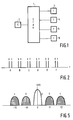
- a transmission medium simultaneously accessible to at least two terminals in this case the medium being an optically reflective star network 1 is connected to an exchange 2 and a plurality of terminals of which only four 3, 4, 5 and 6 are shown here.
- the reflective star network (coupler) distributes a light signal fed to the network by one of the terminals or by the exchange over all the terminals, so that a signal fed to the network by one of the terminals or by the exchange may be received by all the terminals.
- Such a star coupler is known from the journal article "Reflective single-mode fibre-optic passive star couplers" by A.A.M Saleh and H. Kogelnik in Journal of Lightwave Technology, Vol. 6, March 1988, pp. 392-398.
- the terminals may be tuned to one carrier from a number of different optical carriers, such as is represented in Fig. 2.
- the channel A is reserved as an auxiliary channel. On this auxiliary channel all signalling takes place between the exchange and the terminals. If the terminals are not active, they are tuned to the carrier A (Fig. 2) for receiving information from the exchange or for sending information to the exchange. It is then assumed that carrier x in channel A is used for transporting information from the exchange to the terminals and that channel y is used for transporting information from the terminals to the exchange. Needless to observe that it is alternatively possible that a carrier x will suffice per channel, the communication between exchange and terminals then taking place in the half-duplex mode.
- a terminal wishes to have a connection to another terminal, the exchange is informed of this wish through the auxiliary channel.
- the access to the auxiliary channel is to be controlled by means of a protocol.
- this protocol such as, for example, the exchange alternately polling the terminals, a fixed time slot in a frame being reserved for each terminal, or the use of so-called random-access techniques.
- the exchange announces both to the calling terminal and the called terminal on which optical carrier they are to exchange their messages.
- the exchange then provides that only channels which are still free can be allocated to a couple of terminals.
- the calling terminal transmits, for example, on carrier x and the called terminal on carrier y.
- the calling terminal announces this to the exchange, so that the channel used may again be released to other terminals.
- the exchange informs the calling station to which channel and which carrier (x or y) the called station has tuned its receiver. Furthermore, the exchange may announce which subcarrier is to be used. The calling station may then tune its transmitter in the proper fashion and start communicating with the called station. If more than one subcarrier are provided, it is possible for more than one station to communicate simultaneously with an already seized terminal.
- the frequency difference between the carriers x and y for a full-duplex connection between two terminals is to be equal to the intermediate frequency in the terminals.
- the modulation means directly modulate the light generated by the laser, for a full duplex connection between two terminals at least one of the baseband signals is to be modulated on a subcarrier so as to distinguish between these signals after transmission. Angle modulation is then preferably selected as has already been explained hereinbefore.
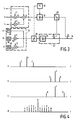
- an input a is connected to a first input of an adder 14.
- An input b is connected to a first input of a multiplier 10.
- a signal having a frequency f1 is applied to a second input of the multiplier 10, whereas the output of the multiplier 10 is connected to a second input of the adder 14.
- An input c is connected to a first input of a multiplier 12.
- a signal having a frequency f2 is applied to a second input of the multiplier 12, whereas the output of the multiplier 12 is connected to a third input of the adder 14.
- the multipliers 10 and 12, combined with the adder 14, form the further modulation means 9 according to the inventive idea.
- the output of the adder 14 is connected to the input of the modulation means in this case a control input of the oscillator.
- This may be a amplitude control input for obtaining an amplitude modulation, but is preferably a frequency modulator.
- the oscillator is in this case a laser 16.
- a tuning element 18 is also connected to the laser 16.
- the output of the laser 16 is connected to a splitter unit 20.
- a first output of the splitter unit 20 is coupled to the glass fibre 34 by means of the send means, in this case a coupling element 22.
- the glass fibre 34 is coupled via the receive means, in this case the coupling element 22, and the mixer means 27, to the input of the demodulation means, in this case a frequency demodulator 28.
- the mixer means comprises a coupling element 24 a first input of which forms an input of the mixer means, and a photodiode 26.
- a second output of the splitter unit 20 is connected to a second input of the coupling element 24.
- the output of the photodiode 26 forms the output of the mixer means.
- This output is coupled to an input of the demodulation means in this case a demodulator 28.
- This may be an amplitude demodulator but, preferably, a frequency modulator is used.
- the output of the demodulator 28 is connected to an input of the further demodulation means 29.
- the input of the further demodulation means is connected to a low-pass filter 36, a first input of a multiplier 30 and a first input of a multiplier 32.
- a signal having a frequency f1 is applied to a second input of the multiplier 30.
- a second input of the multiplier 32 is supplied with a signal having a frequency f2.
- the output of the multiplier 30 is connected to an input of a low-pass filter 38, whereas the output of the multiplier 32 is connected to the input of a low-pass filter 40.
- the output signal of the low-pass filter 36 is available at the output a'. At the outputs b' and c' respectively, the output signals of the low-pass filters 38 and 40 are available.
- the baseband signal s1 to be transmitted will be applied to the input a of this first terminal and in the second terminal the baseband signal s2 to be transmitted will be applied to the input b of this second terminal.
- the baseband signals are data signals having a transmission rate of 100 Mbit/s.
- the baseband signal s1 to be transmitted is present, whereas in the second terminal, at the output of the adder 14 a dual sideband modulated baseband signal with a suppressed carrier is present.
- Frequency modulation is preferably used because the baseband signals modulated on a subcarrier are then available undistorted in the intermediate-frequency signal.
- the output signal of the adder 14 then causes FM modulation of the light emitted by the laser 16.
- the applied frequency swing of the light signal is here 1 GHz.
- Part of this modulated light is fed to the glass fibre 34 by way of the splitter unit 20 and the coupling element 22.
- the coupling element 24 the light received from the glass fibre 34 is combined with the remaining part of the light generated by the laser 16.
- This combination of light signals is applied to the photodiode 26 which produces an intermediate-frequency signal that is representative of the amplitude of the light signal at the input of the photodiode 26. Since the carrier frequencies of the two light signals have values that differ by a value equal to the intermediate frequency, the intermediate-frequency signal at the output of the photodiode 26 has the desired centre frequency.
- the value of the centre frequency used in this system is 3 GHz.
- a third terminal wishes to send a signal to the first terminal, this signal is to be applied to the input c of the third terminal, so that this signal is modulated on a subcarrier having a frequency f2.
- the third terminal is to tune its laser to the same frequency as the second terminal so as to be received by the first terminal.
- the signal coming from the third terminal is then available at output c' of the first terminal.
- Further terminals may similarly communicate with the first or the second terminal, but then there should be provided that a sufficient number of subcarriers can be used.
- the send oscillator is constituted by a LED or a laser 16 having a fixed frequency.
- the modulation means are then constituted by an amplitude control input of the laser (LED) 16.
- the mixer means may then be completely omitted from the receive means.
- the frequency demodulator may then also be omitted.
- the demodulation means are now constituted by the photodiode 26 which is directly coupled to the transmission medium. The effect of this simplification is that there is now only a single optical carrier available.
- a third terminal can still send a message to the first or the second terminal by modulating its baseband signal on a subcarrier and by generating with the signal thus obtained an amplitude modulated light signal and feeding this to the network.
- Fig. 4 various frequency spectrums are shown when terminals as shown in Fig. 3 are used for the case where amplitude modulation is employed, the first terminal maintaining a full duplex connection to the second terminal, and a third terminal sending a message to the first terminal.
- Fig. 4-a, Fig. 4-b and Fig. 4-c the respective frequency spectrums are shown of the signals transmitted by the first, the second and the third terminals.
- Fig. 4-d shows the frequency spectrum of the intermediate-frequency signal in the first terminal.
- the component g in Fig. 4-d is the mixing product of the carrier 1 in Fig. 4-a and the carrier 4 in Fig. 4-b and the carrier 7 in Fig. 4-c.
- the components e and i are the desired mixing products of the carrier 1 in Fig. 4-b and the two sidebands 5 and 6 of Fig. 4-b. These components contain information that is to be transferred from the second terminal to the first terminal.
- the components d and j are the desired mixing products of the carrier 4 in Fig. 4-b and the two sidebands 2 and 3 of Fig. 4-a. These components contain the information to be transferred from the second terminal to the first terminal.
- the components c and k are the desired mixing products of the carrier 1 in Fig. 4-a and the two sidebands 8 and 9 of Fig. 4-c. These components contain the information to be transferred from the third terminal to the first terminal.
- the components a, b, f, h, l, m are unwanted mixing products of the sidebands 2 and 3 of Fig. 4-a with the sidebands 5 and 6 of Fig. 4-b, and with the sidebands 8 and 9 of Fig. 4-c.
- the magnitude of the unwanted mixing products may be restricted by keeping the modulation depth of the amplitude modulation small.
- Fig. 5 shows the spectrum at the output of the demodulator 28 of the first terminal for from the situation in which frequency modulation is employed and in which this first terminal keeps up a full-duplex connection to a second terminal and while, simultaneously, a third terminal sends information to the first terminal.
- the signal s2 transmitted by the second terminal is modulated on the frequency f1
- the signal coming from the third terminal is modulated on a carrier having a frequency f2.
- the signals desired in the first terminal are then available here at the outputs b' and c'.
- the values used for the frequencies f1 and f2 of the subcarriers are 200 MHz and 500 MHz. In the frequency spectrum as shown in Fig. 5 no undesired mixing products are available as a result of the use of frequency modulation.
Landscapes
- Engineering & Computer Science (AREA)
- Computer Networks & Wireless Communication (AREA)
- Signal Processing (AREA)
- Physics & Mathematics (AREA)
- Electromagnetism (AREA)
- Optical Communication System (AREA)
- Digital Transmission Methods That Use Modulated Carrier Waves (AREA)
- Superheterodyne Receivers (AREA)
Applications Claiming Priority (2)
| Application Number | Priority Date | Filing Date | Title |
|---|---|---|---|
| EP91201841 | 1991-07-15 | ||
| EP91201841 | 1991-07-15 |
Publications (2)
| Publication Number | Publication Date |
|---|---|
| EP0523780A2 true EP0523780A2 (de) | 1993-01-20 |
| EP0523780A3 EP0523780A3 (en) | 1993-03-03 |
Family
ID=8207779
Family Applications (1)
| Application Number | Title | Priority Date | Filing Date |
|---|---|---|---|
| EP19920202044 Withdrawn EP0523780A3 (en) | 1991-07-15 | 1992-07-07 | Coherent optical telecommunication network |
Country Status (3)
| Country | Link |
|---|---|
| US (1) | US5371622A (de) |
| EP (1) | EP0523780A3 (de) |
| JP (1) | JPH06132893A (de) |
Cited By (1)
| Publication number | Priority date | Publication date | Assignee | Title |
|---|---|---|---|---|
| EP0660546A1 (de) * | 1993-12-24 | 1995-06-28 | Koninklijke Philips Electronics N.V. | Übertragungsnetz mit Vielfachzugriff und Unterträger |
Families Citing this family (5)
| Publication number | Priority date | Publication date | Assignee | Title |
|---|---|---|---|---|
| US5847853A (en) * | 1995-12-29 | 1998-12-08 | Micron Technology, Inc. | Modulation and demodulation of light to facilitate transmission of information |
| US6339487B1 (en) | 1997-03-24 | 2002-01-15 | At&T Corp. | Bi-directional optical transmission system |
| AU6782800A (en) * | 1999-08-16 | 2001-07-03 | Z-Force Corporation | System of reusable software parts for implementing concurrency and hardware access, and methods of use |
| US6597479B1 (en) * | 1999-10-22 | 2003-07-22 | Adtran, Inc. | Fiber quadrupler device method for providing full duplex communications to a synchronous optical network over a single optical fiber |
| CN101399618B (zh) * | 2007-09-26 | 2011-06-15 | 华为技术有限公司 | 光线路终端、无源光网络和射频信号传输方法 |
Family Cites Families (7)
| Publication number | Priority date | Publication date | Assignee | Title |
|---|---|---|---|---|
| US4635246A (en) * | 1983-10-20 | 1987-01-06 | The United States Of America As Represented By The Secretary Of The Navy | Frequency multiplex system using injection locking of multiple laser diodes |
| JP2561464B2 (ja) * | 1985-06-19 | 1996-12-11 | ブリティシュ・テレコミュニケーションズ・パブリック・リミテッド・カンパニ | 光結合アセンブリ |
| DE3827228A1 (de) * | 1988-08-11 | 1990-02-15 | Standard Elektrik Lorenz Ag | Sende/empfangsteil fuer ein bidirektionales kohaerent-optisches uebertragungssystem |
| EP0359205A3 (de) * | 1988-09-14 | 1991-11-13 | Gte Laboratories Incorporated | Optisches Übertragungssystem zur gleichzeitigen Übertragung eines digitalen Basisbandsignals und mehreren Mikrowellenhilfsträgern |
| US5134509A (en) * | 1988-12-22 | 1992-07-28 | Gte Laboratories Incorporated | Coherent subcarrier multiplexed optical communication system |
| US4989200A (en) * | 1988-12-22 | 1991-01-29 | Gte Laboratories Incorporated | Coherent subcarrier multiplexed optical communication system |
| EP0419710A1 (de) * | 1989-09-28 | 1991-04-03 | Siemens Aktiengesellschaft | Bidirektionales LWL-Telekommunikationssystem für Wellenlängengetrenntlagebetrieb (Bidirektionales WDM) zwischen einer zentralen Telekommunikationsstelle und einer Mehrzahl von dezentralen Telekommunikationsstellen |
-
1992
- 1992-07-07 EP EP19920202044 patent/EP0523780A3/en not_active Withdrawn
- 1992-07-09 US US07/910,953 patent/US5371622A/en not_active Expired - Fee Related
- 1992-07-14 JP JP4186992A patent/JPH06132893A/ja active Pending
Cited By (2)
| Publication number | Priority date | Publication date | Assignee | Title |
|---|---|---|---|---|
| EP0660546A1 (de) * | 1993-12-24 | 1995-06-28 | Koninklijke Philips Electronics N.V. | Übertragungsnetz mit Vielfachzugriff und Unterträger |
| BE1007910A3 (nl) * | 1993-12-24 | 1995-11-14 | Koninkl Philips Electronics Nv | Multiple acces telecommunicatienetwerk. |
Also Published As
| Publication number | Publication date |
|---|---|
| EP0523780A3 (en) | 1993-03-03 |
| JPH06132893A (ja) | 1994-05-13 |
| US5371622A (en) | 1994-12-06 |
Similar Documents
| Publication | Publication Date | Title |
|---|---|---|
| US5613210A (en) | Telecommunication network for transmitting information to a plurality of stations over a single channel | |
| JP3183685B2 (ja) | 光通信システム | |
| CA1199074A (en) | Communications network with optical channels | |
| US5546190A (en) | Carrier and clock recovery for lightwave systems | |
| EP0772312A2 (de) | Optisches Kommunikationssystem mit gemultiplexten Unterträgern | |
| US5323255A (en) | Transceiver arrangement using TDM to transmit assigned subcarrier waveforms | |
| US6922431B1 (en) | Communication using spread spectrum methods over optical fibers | |
| EP0222384B1 (de) | Full Duplex optisches Übertragungssystem | |
| US4754452A (en) | Optical local area network using a common optical carrier with separate user angle modulation | |
| AU622523B2 (en) | Optical subscriber loop system | |
| US5491575A (en) | Passive optical telecommunication system | |
| AU623498B2 (en) | Optical subscriber loop system | |
| US5371622A (en) | Coherent optical telecommunication network wherein each send/receive terminal can simultaneously communicate with more than one other send/receive terminal | |
| JP3219255B2 (ja) | 光通信方式 | |
| EP0660546B1 (de) | Übertragungsnetz mit Vielfachzugriff und Unterträger | |
| WO2000057582A1 (en) | Optically modulated laser beam transceiver system | |
| JP2775692B2 (ja) | 光通信方式 | |
| JP2003198486A (ja) | 双方向光伝送システム及び光送信装置並びに光受信装置 | |
| Mudhar | A hybrid approach to the transmission of telephony over a passive optical network | |
| Schubert et al. | Wireless access to ATM-networks based on optical microwave generation | |
| JP2002009738A (ja) | 光伝送装置 | |
| JPH07221736A (ja) | サブキャリア多重光伝送方法 | |
| JPH1117659A (ja) | 光通信ネットワーク | |
| JP2001136128A (ja) | 光通信装置 |
Legal Events
| Date | Code | Title | Description |
|---|---|---|---|
| PUAI | Public reference made under article 153(3) epc to a published international application that has entered the european phase |
Free format text: ORIGINAL CODE: 0009012 |
|
| PUAL | Search report despatched |
Free format text: ORIGINAL CODE: 0009013 |
|
| AK | Designated contracting states |
Kind code of ref document: A2 Designated state(s): DE FR GB IT |
|
| AK | Designated contracting states |
Kind code of ref document: A3 Designated state(s): DE FR GB IT |
|
| 17P | Request for examination filed |
Effective date: 19930820 |
|
| 17Q | First examination report despatched |
Effective date: 19951024 |
|
| STAA | Information on the status of an ep patent application or granted ep patent |
Free format text: STATUS: THE APPLICATION IS DEEMED TO BE WITHDRAWN |
|
| 18D | Application deemed to be withdrawn |
Effective date: 19980203 |