EP0521805A1 - Indicateur de défaut pour un parafoudre - Google Patents
Indicateur de défaut pour un parafoudre Download PDFInfo
- Publication number
- EP0521805A1 EP0521805A1 EP92420228A EP92420228A EP0521805A1 EP 0521805 A1 EP0521805 A1 EP 0521805A1 EP 92420228 A EP92420228 A EP 92420228A EP 92420228 A EP92420228 A EP 92420228A EP 0521805 A1 EP0521805 A1 EP 0521805A1
- Authority
- EP
- European Patent Office
- Prior art keywords
- resistor
- hand
- indicator
- arrester
- envelope
- Prior art date
- Legal status (The legal status is an assumption and is not a legal conclusion. Google has not performed a legal analysis and makes no representation as to the accuracy of the status listed.)
- Granted
Links
Images

Classifications
-
- H—ELECTRICITY
- H01—ELECTRIC ELEMENTS
- H01T—SPARK GAPS; OVERVOLTAGE ARRESTERS USING SPARK GAPS; SPARKING PLUGS; CORONA DEVICES; GENERATING IONS TO BE INTRODUCED INTO NON-ENCLOSED GASES
- H01T1/00—Details of spark gaps
- H01T1/12—Means structurally associated with spark gap for recording operation thereof
-
- H—ELECTRICITY
- H01—ELECTRIC ELEMENTS
- H01C—RESISTORS
- H01C7/00—Non-adjustable resistors formed as one or more layers or coatings; Non-adjustable resistors made from powdered conducting material or powdered semi-conducting material with or without insulating material
- H01C7/10—Non-adjustable resistors formed as one or more layers or coatings; Non-adjustable resistors made from powdered conducting material or powdered semi-conducting material with or without insulating material voltage responsive, i.e. varistors
- H01C7/12—Overvoltage protection resistors
- H01C7/126—Means for protecting against excessive pressure or for disconnecting in case of failure
Definitions
- the present invention relates to fault or short-circuit indicating devices, intended to equip lightning arresters mounted along high or medium voltage overhead electrical lines.
- Such a device comprises an elastically deformable rectilinear strip, one of the ends of which, associated with a lock, is released when a defect appears in the arrester associated with said device.
- the means for releasing the lock are dependent on a filter formed by two windings in parallel, one of which is of the inductive type in order to stop the current resulting from the shock waves at very high di / dt, while the another is resistive in nature in order to slow down the passage of a possible "short circuit" current which can pass through the inductive winding in series with a fusible wire, the melting of which has the effect of releasing the indicator.
- Such an indicator is of low sensitivity, because it does not work below 70 amps.
- the filter system requires an inductance value which is difficult to achieve industrially and at low cost.
- the principle of selecting currents by the di / dt relationship has the disadvantage of allowing currents of significant peak value to pass through the wire in the event of lightning waves. The duration of the lightning wave is not sufficient to destroy the wire, but premature aging of the metal may appear if the lightning phenomenon recurs.
- the improvements which are the subject of the present invention aim to remedy these drawbacks and to allow the production of a surge arrester fault indicator which is actuated as a function of the value of the intensity of the current generated by the network after switching on. short circuit of the arrester.
- the fault indicator according to the invention is defined in claim 1.
- this indicator comprises two opposite electrodes which are joined on the one hand in series by a device with non-linear voltage-current characteristic such as a spark gap or a low voltage varistor through which any lightning waves pass, and on the other hand in derivation by a resistor which does not react during a lightning wave, but rises in temperature during the passage of the current generated by the network to destroy at least partially a sleeve surrounding the indicator, in the event of accidental short-circuiting of the arrester connected in series with this indicator.
- a device with non-linear voltage-current characteristic such as a spark gap or a low voltage varistor through which any lightning waves pass
- the rise in temperature of the resistor can destroy it and cause the elimination of an elastic band, the ends of which are associated with said resistor.
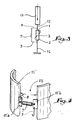
- Fig. 1 is a longitudinal section of a fault indicator established in accordance with the invention.
- Fig. 2 is a section along II-II (fig. 1).
- Fig. 3 shows the electrical diagram of the fault indicator according to the invention.
- Fig. 4 is a detailed perspective view of an alternative embodiment of the invention.
- a first embodiment of the fault indicator according to the invention which essentially comprises two electrodes 1 and 2, provided cylindrical, and between which a low voltage varistor 3 is inserted, two intermediate washers 4 ensuring a good contact between said electrodes and the varistor.
- the assembly of the three aforementioned elements is carried out by means of a tube 5 of insulating material having a vertical slot, so that it affects in cross-section the shape of an inverted C (fig. 2).
- the tube 5 is associated with the electrodes 1 and 2 by means of shims 6.
- a resistor 7 is connected by conductors 8 and 9, respectively to the electrodes 1 and 2, said resistor being located in the slit 5a of the tube 5. All the aforementioned elements is placed in a mold for molding an outer shell 10 made for example by means of a silicone elastomer for example. It is observed that the resistor 7 tangents one of the external generators of the envelope 10 for reasons which will be explained better below.
- a tubular sleeve 11 made of elastomer and which is put in place by elastic extension.
- the sleeve 11 is preferably colored.
- the electrode 1 is connected by any suitable means, for example by a conductor 12 (fig. 3) to a surge arrester 13, while the electrode 2 is connected to earth by a cable 14 (fig. 3).
- the operation is as follows: during a lightning strike, the intensity peak is conducted to the ground by crossing the varistor 3, the current deflected in the resistor 7 does not cause a significant heating of the latter due to the very short duration of the lightning strike.
- the arrester 13 is destroyed, a current is generated by the network, and is maintained until the intervention of the network protections.
- the resulting duration causes heating of the resistor sufficient to melt the sleeve 11 at its level given the proximity of the resistor and the sleeve.
- the sleeve is produced in the form of a strip 11 ′ which does not occupy the entire periphery of the envelope 10, so that between its ends there is a space 15.
- Each of the ends of the strip 11 ′ Is provided with a metal terminal 11 ′ a , 11 ′ b to each of which is fixed the corresponding end of the resistor 7 which thus constitutes a means for retaining in place the interrupted strip 11 ′.
- the terminals 11 ′ a and 11 ′ b are respectively joined to the conductors 8 and 9.
- a fault indicator has thus been produced which responds particularly well to the wishes of the practice and which allows in particular, due to the current / voltage characteristics of the two components in parallel, that practically all of the leakage current of the arrester 13 passes through the resistor 7, so that the varistor 3 does not age in normal operation.
- the rise in temperature of the resistor 7 can act on a remote signaling circuit facilitating the finding of destruction of the fault indicator.
Landscapes
- Engineering & Computer Science (AREA)
- Microelectronics & Electronic Packaging (AREA)
- Physics & Mathematics (AREA)
- Electromagnetism (AREA)
- Thermistors And Varistors (AREA)
- Emergency Protection Circuit Devices (AREA)
- Insulators (AREA)
Abstract
Description
- La présente invention a trait aux dispositifs indicateurs de défaut ou de court-circuit, destinés à équiper les parafoudres montés le long des lignes électriques aériennes à haute ou moyenne tension.
- On connaît des dispositifs de ce genre, par exemple celui décrit dans le document FR-A-2 603 418 (FERRAZ) et qui comporte un dispositif visuel incorporé en vue de signaler de manière parfaitement apparente le défaut éventuel d'un parafoudre auquel il est associé.
- Un tel dispositif comprend une bande rectiligne élastiquement déformable dont l'une des extrémités, associée à un verrou, est libérée lorsqu'un défaut apparaît sur le parafoudre associé audit dispositif. Les moyens de libération du verrou sont sous la dépendance d'un filtre formé de deux bobinages en parallèle dont l'un est de type selfique afin d'arrêter le courant résultant des ondes de choc à très fort di/dt, tandis que l'autre est de nature résistive afin de freiner le passage d'un courant éventuel "de court circuit" et qui peut traverser le bobinage selfique en série avec un fil fusible, dont la fusion a pour effet de libérer l'indicateur.
- Un tel indicateur est de faible sensibilité, car il ne fonctionne pas en deçà de 70 ampères. En outre, le système de filtre nécessite une valeur de self difficilement réalisable de façon industrielle et à faible coût. Enfin, le principe de sélection des courants par la relation di/dt présente l'inconvénient de laisser passer tout de même dans le fil des courants de valeur de crêté importantes en cas d'onde de foudre. La durée de l'onde de foudre n'est pas suffisante pour détruire le fil, mais il peut apparaître un vieillissement prématuré du métal en cas de répétition du phénomène de foudre.
- Les perfectionnements qui font l'objet de la présente invention visent à remédier à ces inconvénients et à permettre la réalisation d'un indicateur de défaut de parafoudre qui est actionné en fonction de la valeur d'intensité du courant généré par le réseau après mise en courtcircuit du parafoudre.
- L'indicateur de défaut suivant l'invention est défini à la revendication 1.
- En fait cet indicateur comprend deux électrodes opposées qui sont réunies d'une part en série par un dispositif à caractéristique tension-courant non linéaire tel qu'un éclateur ou une varistance basse tension à travers lequel transitent les éventuelles ondes de foudre, et d'autre part en dérivation par une résistance qui ne réagit pas lors d'une onde de foudre, mais s'élève en température lors du passage du courant généré par le réseau pour détruire au moins en partie un manchon entourant l'indicateur, en cas de mise en court-circuit accidentel du parafoudre branché en série avec cet indicateur.
- En variante, l'élévation de température de la résistance peut la détruire et provoquer l'élimination d'une bande élastique dont les extrémités sont associées à ladite résistance.
- Le dessin annexé, donné à titre d'exemple, permettra de mieux comprendre l'invention, les caractéristiques qu'elle présente et les avantages qu'elle est susceptible de procurer :
- Fig. 1 est une coupe longitudinale d'un indicateur de défaut établi conformément à l'invention.
- Fig. 2 est une coupe suivant II-II (fig. 1).
- Fig. 3 représente le schéma électrique de l'indicateur de défaut suivant l'invention.
- Fig. 4 est une vue de détail en perspective d'une variante de réalisation de l'invention.
- On a illustré en fig. 1 et 2 un premier mode d'exécution de l'indicateur de défaut suivant l'invention, qui comprend essentiellement deux électrodes 1 et 2, prévues cylindriques, et entre lesquelles est insérée une varistance à basse tension 3, deux rondelles intercalaires 4 assurant un bon contact entre lesdites électrodes et la varistance. L'assemblage des trois éléments précités est effectué au moyen d'un tube 5 en matière isolante présentant une fente verticale, de telle sorte qu'il affecte en section transversale la forme d'un C inversé (fig. 2). Le tube 5 est associé aux électrodes 1 et 2 au moyen de cales 6.
- Il convient d'observer qu'aux lieu et place de la varistance 3, on peut prévoir un éclateur à électrodes circulaires ou tout autre dispositif à caractéristique tension-courant non linéaire.
- Une résistance 7 est branchée par des conducteurs 8 et 9, respectivement aux électrodes 1 et 2, ladite résistance étant située dans la fente 5a du tube 5. L'ensemble des éléments précité est placé dans un moule permettant de mouler une enveloppe extérieure 10 réalisée par exemple au moyen d'un élastomère silicone par exemple. On observe que la résistance 7 tangente l'une des génératrices extérieures de l'enveloppe 10 pour des raisons qu'on expliquera mieux plus loin.
- Autour de l'enveloppe 10 est placé sous tension un manchon tubulaire 11 réalisé en élastomère et qui est mis en place par allongement élastique. Le manchon 11 est de préférence coloré.
- L'électrode 1 est branchée par tous moyens appropriés, par exemple par un conducteur 12 (fig. 3) à un parafoudre 13, tandis que l'électrode 2 est reliée à la terre par un câble 14 (fig. 3).
- Le fonctionnement est le suivant : lors d'un coup de foudre, la crête d'intensité est conduite à la terre en traversant la varistance 3, le courant dévié dans la résistance 7 ne provoque par un échauffement significatif de cette dernière du fait de la très faible durée du coup de foudre.
- Par contre, si pour une raison ou une autre, le parafoudre 13 est détruit un courant est généré par le réseau, et se maintient jusqu'à l'intervention des protections du réseau. La durée qui en résulte provoque un échauffement de la résistance suffisant pour faire fondre le manchon 11 à son niveau étant donné la proximité de la résistance et du manchon. Ainsi, tout surveillant peut voir que l'indicateur de défaut à fonctionné (par disparition du manchon 11) de telle sorte qu'il sait que le parafoudre correspondant est hors d'usage.
- Dans la variante de fig. 4, le manchon est réalisé sous la forme d'une bande 11′ qui n'occupe pas toute la périphérie de l'enveloppe 10, de telle sorte qu'entre ses extrémités il existe un espace 15. Chacune des extrémités de la bande 11′ est pourvue d'une borne métallique 11′a, 11′b à chacune desquelles est fixée l'extrémité correspondante de la résistance 7 qui constitue ainsi un moyen de retenue en place de la bande interrompue 11′ . Les bornes 11′a et 11′b sont respectivement réunies aux conducteurs 8 et 9.
- Lorsque le réseau émet un courant après mise en court-circuit du parafoudre correspondant à l'indicateur de défaut considéré, l'intensité de ce courant fait fondre la résistance 7 qui libère ainsi les deux extrémités de la bande 11′ qui, du fait de son élasticité, se sépare de l'indicateur de défaut. Là encore, le surveillant constate visuellement l'absence de la bande 11′ et en déduit que le parafoudre correspondant est hors d'usage.
- On a ainsi réalisé un indicateur de défaut qui répond particulièrement bien aux desiderata de la pratique et qui permet en particulier, du fait des caractéristiques courant/tension des deux composants en parallèles, que pratiquement tout le courant de fuite du parafoudre 13 passe à travers la résistance 7, de telle sorte que la varistance 3 ne vieillit pas en fonctionnement normal.
- On notera que l'élévation en température de la résistance 7 peut agir sur un circuit de signalisation à distance facilitant le constat de destruction de l'indicateur de défaut.
Claims (3)
- Indicateur de défaut pour parafoudre (13) placé sur un réseau aérien d'alimentation électrique à haute ou moyenne tension, caractérisé en ce qu'il comprend deux électrodes (1, 2) réunies d'une part en série par un dispositif (3) à caractéristique tension-courant non linéaire tel qu'une varistance ou un éclateur, et d'autre part en dérivation par une résistance (7) qui, sans réagir lors d'une onde de foudre, s'élève en température lors du passage du courant généré par le réseau à la suite de cette onde, en assurant par fusion la libération d'un organe de signalisation visuelle (11, 11′) entourant l'enveloppe (10) de l'ensemble.
- Indicateur suivant la revendication 1, caractérisé en ce que la résistance (7) retient les deux extrémités d'une bande élastique (11′) engagée autour de l'enveloppe (10).
- Indicateur suivant l'une quelconque des revendications 1 et 2, caractérisé en ce que l'élévation en température de la résistance (7) agit sur un circuit de signalisation à distance.
Applications Claiming Priority (5)
| Application Number | Priority Date | Filing Date | Title |
|---|---|---|---|
| FR9108563A FR2678764A1 (fr) | 1991-07-03 | 1991-07-03 | Indicateur de defaut pour un parafoudre. |
| FR9108563 | 1991-07-03 | ||
| CH03708/92A CH687486A5 (fr) | 1991-07-03 | 1992-12-03 | Indicateur de défaut pour un parafoudre. |
| PT101114A PT101114B (pt) | 1991-07-03 | 1992-12-07 | Indicador de defeito para para-raios |
| CS923807A CZ282376B6 (cs) | 1991-07-03 | 1992-12-21 | Indikátor závad bleskojistky |
Publications (2)
| Publication Number | Publication Date |
|---|---|
| EP0521805A1 true EP0521805A1 (fr) | 1993-01-07 |
| EP0521805B1 EP0521805B1 (fr) | 1994-12-28 |
Family
ID=27428667
Family Applications (1)
| Application Number | Title | Priority Date | Filing Date |
|---|---|---|---|
| EP92420228A Expired - Lifetime EP0521805B1 (fr) | 1991-07-03 | 1992-07-02 | Indicateur de défaut pour un parafoudre |
Country Status (7)
| Country | Link |
|---|---|
| EP (1) | EP0521805B1 (fr) |
| CH (1) | CH687486A5 (fr) |
| CZ (1) | CZ282376B6 (fr) |
| DE (1) | DE69201021T2 (fr) |
| ES (1) | ES2066589T3 (fr) |
| FR (1) | FR2678764A1 (fr) |
| PT (1) | PT101114B (fr) |
Cited By (1)
| Publication number | Priority date | Publication date | Assignee | Title |
|---|---|---|---|---|
| WO1998006111A1 (fr) * | 1996-08-01 | 1998-02-12 | Siemens Aktiengesellschaft | Limiteur de surtension |
Families Citing this family (7)
| Publication number | Priority date | Publication date | Assignee | Title |
|---|---|---|---|---|
| US10319545B2 (en) | 2016-11-30 | 2019-06-11 | Iskra Za{hacek over (s)}{hacek over (c)}ite d.o.o. | Surge protective device modules and DIN rail device systems including same |
| US10340110B2 (en) | 2017-05-12 | 2019-07-02 | Raycap IP Development Ltd | Surge protective device modules including integral thermal disconnect mechanisms and methods including same |
| US10685767B2 (en) | 2017-09-14 | 2020-06-16 | Raycap IP Development Ltd | Surge protective device modules and systems including same |
| US11223200B2 (en) * | 2018-07-26 | 2022-01-11 | Ripd Ip Development Ltd | Surge protective devices, circuits, modules and systems including same |
| US11862967B2 (en) | 2021-09-13 | 2024-01-02 | Raycap, S.A. | Surge protective device assembly modules |
| US11723145B2 (en) | 2021-09-20 | 2023-08-08 | Raycap IP Development Ltd | PCB-mountable surge protective device modules and SPD circuit systems and methods including same |
| US11990745B2 (en) | 2022-01-12 | 2024-05-21 | Raycap IP Development Ltd | Methods and systems for remote monitoring of surge protective devices |
Citations (3)
| Publication number | Priority date | Publication date | Assignee | Title |
|---|---|---|---|---|
| EP0262056A1 (fr) * | 1986-08-28 | 1988-03-30 | FERRAZ Société Anonyme | Indicateur pour la signalisation de la mise en court-circuit d'un parafoudre |
| FR2641423A1 (fr) * | 1988-12-30 | 1990-07-06 | Ferraz | Dispositif parafoudre pour la protection des lignes electriques |
| EP0419386A1 (fr) * | 1989-09-22 | 1991-03-27 | Societe Industrielle De Materiel Electrique Simel | Dispositif parafoudre à indicateur visuel de défaut |
-
1991
- 1991-07-03 FR FR9108563A patent/FR2678764A1/fr active Granted
-
1992
- 1992-07-02 EP EP92420228A patent/EP0521805B1/fr not_active Expired - Lifetime
- 1992-07-02 ES ES92420228T patent/ES2066589T3/es not_active Expired - Lifetime
- 1992-07-02 DE DE69201021T patent/DE69201021T2/de not_active Expired - Fee Related
- 1992-12-03 CH CH03708/92A patent/CH687486A5/fr not_active IP Right Cessation
- 1992-12-07 PT PT101114A patent/PT101114B/pt not_active IP Right Cessation
- 1992-12-21 CZ CS923807A patent/CZ282376B6/cs not_active IP Right Cessation
Patent Citations (3)
| Publication number | Priority date | Publication date | Assignee | Title |
|---|---|---|---|---|
| EP0262056A1 (fr) * | 1986-08-28 | 1988-03-30 | FERRAZ Société Anonyme | Indicateur pour la signalisation de la mise en court-circuit d'un parafoudre |
| FR2641423A1 (fr) * | 1988-12-30 | 1990-07-06 | Ferraz | Dispositif parafoudre pour la protection des lignes electriques |
| EP0419386A1 (fr) * | 1989-09-22 | 1991-03-27 | Societe Industrielle De Materiel Electrique Simel | Dispositif parafoudre à indicateur visuel de défaut |
Cited By (1)
| Publication number | Priority date | Publication date | Assignee | Title |
|---|---|---|---|---|
| WO1998006111A1 (fr) * | 1996-08-01 | 1998-02-12 | Siemens Aktiengesellschaft | Limiteur de surtension |
Also Published As
| Publication number | Publication date |
|---|---|
| PT101114A (pt) | 1994-07-29 |
| DE69201021D1 (de) | 1995-02-09 |
| FR2678764A1 (fr) | 1993-01-08 |
| CZ380792A3 (en) | 1994-07-13 |
| PT101114B (pt) | 1999-09-30 |
| ES2066589T3 (es) | 1995-03-01 |
| CZ282376B6 (cs) | 1997-07-16 |
| FR2678764B1 (fr) | 1995-02-10 |
| CH687486A5 (fr) | 1996-12-13 |
| DE69201021T2 (de) | 1995-05-24 |
| EP0521805B1 (fr) | 1994-12-28 |
Similar Documents
| Publication | Publication Date | Title |
|---|---|---|
| EP0262056B1 (fr) | Indicateur pour la signalisation de la mise en court-circuit d'un parafoudre | |
| FR2815767A1 (fr) | Sectionneur a fusible compact | |
| EP0318339B1 (fr) | Dispositif parafoudre comprenant au moins un élément fusible | |
| EP0521805B1 (fr) | Indicateur de défaut pour un parafoudre | |
| FR2680611A1 (fr) | Dispositif de protection contre les surtensions. | |
| FR2848353A1 (fr) | Dispositif de protection contre des surtensions | |
| CA2251240C (fr) | Montage de parafoudre pour ligne electrique aerienne avec indicateur d'un defaut de fonctionnement du parafoudre | |
| BE897439A (fr) | Dispositif de protection contre les surtensions | |
| FR2574589A1 (fr) | Dispositif de mise en court-circuit exterieur de faible encombrement | |
| EP0564334B1 (fr) | Dispositif pour la détection et la signalisation d'un courant de défaut dans un parafoudre ou un isolateur | |
| EP0867896A1 (fr) | Dispositif de protection d'un circuit électrique basse tension, module pour un tel dispositif de protection, et circuit pour le module | |
| EP3244504B1 (fr) | Dispositif de protection contre les surtensions transitoires | |
| US2272370A (en) | Electrical protective device | |
| FR1426025A (fr) | Plaquette à bornes avec dispositif sectionneur | |
| FR2641423A1 (fr) | Dispositif parafoudre pour la protection des lignes electriques | |
| EP0782753B1 (fr) | Dispositif parafoudre | |
| EP0085074B1 (fr) | Dispositif de protection contre la surtension dans un reseau de distribution electrique | |
| FR2691301A1 (fr) | Générateur de signal pour la télé-détection des défauts de fonctionnement des parafoudres montés sur les lignes électriques de distribution. | |
| US2526370A (en) | Fuse device for high-voltage circuits | |
| FR2564681A1 (fr) | Element pour cloture de protection a detection de coupure | |
| FR2670624A1 (fr) | Court-circuit et boitier pour parafoudre. | |
| EP0755105B1 (fr) | Module de protection à signalisation de défaut et ensemble de raccordement à protection | |
| FR2655477A1 (fr) | Dispositif de protection a indicateur visuel de defaut pour reseaux electriques aeriens. | |
| FR2701161A1 (fr) | Module à protection pour lignes téléphoniques, informatiques, ou analogues. | |
| US842628A (en) | Substation-protector. |
Legal Events
| Date | Code | Title | Description |
|---|---|---|---|
| PUAI | Public reference made under article 153(3) epc to a published international application that has entered the european phase |
Free format text: ORIGINAL CODE: 0009012 |
|
| AK | Designated contracting states |
Kind code of ref document: A1 Designated state(s): BE DE ES FR GB IT |
|
| 17P | Request for examination filed |
Effective date: 19930309 |
|
| 17Q | First examination report despatched |
Effective date: 19940428 |
|
| GRAA | (expected) grant |
Free format text: ORIGINAL CODE: 0009210 |
|
| AK | Designated contracting states |
Kind code of ref document: B1 Designated state(s): BE DE ES FR GB IT |
|
| REF | Corresponds to: |
Ref document number: 69201021 Country of ref document: DE Date of ref document: 19950209 |
|
| REG | Reference to a national code |
Ref country code: ES Ref legal event code: FG2A Ref document number: 2066589 Country of ref document: ES Kind code of ref document: T3 |
|
| ITF | It: translation for a ep patent filed |
Owner name: MODIANO & ASSOCIATI S.R.L. |
|
| GBT | Gb: translation of ep patent filed (gb section 77(6)(a)/1977) |
Effective date: 19950306 |
|
| PLBE | No opposition filed within time limit |
Free format text: ORIGINAL CODE: 0009261 |
|
| STAA | Information on the status of an ep patent application or granted ep patent |
Free format text: STATUS: NO OPPOSITION FILED WITHIN TIME LIMIT |
|
| 26N | No opposition filed | ||
| PGFP | Annual fee paid to national office [announced via postgrant information from national office to epo] |
Ref country code: FR Payment date: 20010627 Year of fee payment: 10 |
|
| PGFP | Annual fee paid to national office [announced via postgrant information from national office to epo] |
Ref country code: DE Payment date: 20010717 Year of fee payment: 10 |
|
| PGFP | Annual fee paid to national office [announced via postgrant information from national office to epo] |
Ref country code: GB Payment date: 20010720 Year of fee payment: 10 |
|
| PGFP | Annual fee paid to national office [announced via postgrant information from national office to epo] |
Ref country code: BE Payment date: 20010801 Year of fee payment: 10 |
|
| PGFP | Annual fee paid to national office [announced via postgrant information from national office to epo] |
Ref country code: ES Payment date: 20010802 Year of fee payment: 10 |
|
| REG | Reference to a national code |
Ref country code: GB Ref legal event code: IF02 |
|
| PG25 | Lapsed in a contracting state [announced via postgrant information from national office to epo] |
Ref country code: GB Free format text: LAPSE BECAUSE OF NON-PAYMENT OF DUE FEES Effective date: 20020702 |
|
| PG25 | Lapsed in a contracting state [announced via postgrant information from national office to epo] |
Ref country code: ES Free format text: LAPSE BECAUSE OF NON-PAYMENT OF DUE FEES Effective date: 20020703 |
|
| PG25 | Lapsed in a contracting state [announced via postgrant information from national office to epo] |
Ref country code: BE Free format text: LAPSE BECAUSE OF NON-PAYMENT OF DUE FEES Effective date: 20020731 |
|
| BERE | Be: lapsed |
Owner name: S.A. *FERRAZ Effective date: 20020731 |
|
| PG25 | Lapsed in a contracting state [announced via postgrant information from national office to epo] |
Ref country code: DE Free format text: LAPSE BECAUSE OF NON-PAYMENT OF DUE FEES Effective date: 20030201 |
|
| GBPC | Gb: european patent ceased through non-payment of renewal fee |
Effective date: 20020702 |
|
| PG25 | Lapsed in a contracting state [announced via postgrant information from national office to epo] |
Ref country code: FR Free format text: LAPSE BECAUSE OF NON-PAYMENT OF DUE FEES Effective date: 20030331 |
|
| REG | Reference to a national code |
Ref country code: FR Ref legal event code: ST |
|
| REG | Reference to a national code |
Ref country code: ES Ref legal event code: FD2A Effective date: 20030811 |
|
| PG25 | Lapsed in a contracting state [announced via postgrant information from national office to epo] |
Ref country code: IT Free format text: LAPSE BECAUSE OF NON-PAYMENT OF DUE FEES;WARNING: LAPSES OF ITALIAN PATENTS WITH EFFECTIVE DATE BEFORE 2007 MAY HAVE OCCURRED AT ANY TIME BEFORE 2007. THE CORRECT EFFECTIVE DATE MAY BE DIFFERENT FROM THE ONE RECORDED. Effective date: 20050702 |