EP0521514A2 - Optisches Übertragungssystem mit Frequenzmultiplexierung - Google Patents
Optisches Übertragungssystem mit Frequenzmultiplexierung Download PDFInfo
- Publication number
- EP0521514A2 EP0521514A2 EP92111277A EP92111277A EP0521514A2 EP 0521514 A2 EP0521514 A2 EP 0521514A2 EP 92111277 A EP92111277 A EP 92111277A EP 92111277 A EP92111277 A EP 92111277A EP 0521514 A2 EP0521514 A2 EP 0521514A2
- Authority
- EP
- European Patent Office
- Prior art keywords
- optical
- frequency
- signal
- division multiplexing
- filter
- Prior art date
- Legal status (The legal status is an assumption and is not a legal conclusion. Google has not performed a legal analysis and makes no representation as to the accuracy of the status listed.)
- Granted
Links
Images


Classifications
-
- H—ELECTRICITY
- H04—ELECTRIC COMMUNICATION TECHNIQUE
- H04B—TRANSMISSION
- H04B10/00—Transmission systems employing electromagnetic waves other than radio-waves, e.g. infrared, visible or ultraviolet light, or employing corpuscular radiation, e.g. quantum communication
- H04B10/50—Transmitters
- H04B10/572—Wavelength control
-
- H—ELECTRICITY
- H04—ELECTRIC COMMUNICATION TECHNIQUE
- H04B—TRANSMISSION
- H04B10/00—Transmission systems employing electromagnetic waves other than radio-waves, e.g. infrared, visible or ultraviolet light, or employing corpuscular radiation, e.g. quantum communication
- H04B10/50—Transmitters
-
- H—ELECTRICITY
- H04—ELECTRIC COMMUNICATION TECHNIQUE
- H04B—TRANSMISSION
- H04B10/00—Transmission systems employing electromagnetic waves other than radio-waves, e.g. infrared, visible or ultraviolet light, or employing corpuscular radiation, e.g. quantum communication
- H04B10/50—Transmitters
- H04B10/501—Structural aspects
- H04B10/506—Multiwavelength transmitters
-
- H—ELECTRICITY
- H04—ELECTRIC COMMUNICATION TECHNIQUE
- H04B—TRANSMISSION
- H04B10/00—Transmission systems employing electromagnetic waves other than radio-waves, e.g. infrared, visible or ultraviolet light, or employing corpuscular radiation, e.g. quantum communication
- H04B10/50—Transmitters
- H04B10/508—Pulse generation, e.g. generation of solitons
Definitions
- the present invention relates to an optical transmission system utilizing the optical frequency division multiplexing technology for sending a large volume of information by means of a single optical fiber.
- An optical frequency division multiplexing transmission system (the frequency division multiplexing is hereinafter referred to as "FDM") normally comprises an optical FDM transmitter equipment including a plurality of transmission optical sources (in the number of N, where N is a natural number of 1 or more), an optical fiber for transmitting an optical FDM signal and an optical FDM receiver including a plurality (a number N) of heterodyne optical receivers.
- the frequency interval of a transmission optical source is normally stabilized at a predetermined value of Dop.
- Each heterodyne optical receiver (the n-th one, for example, where n is a natural number satisfying the relation 1 ⁇ n ⁇ N) receives only an optical signal outputted from a corresponding (n-th) optical source on transmitter side.
- a conventional optical FDM transmission system is described, for example in IEEE Photonics Technology Letters, Vol. 2, No. 12, pp. 914-916.
- the frequency of a local optical source (hereinafter referred to as “the local frequency”) is controlled in such a manner as to follow the variations in the central frequency of a received optical signal (hereinafter referred to as “the optical signal frequency”), thereby stabilizing the difference frequency (hereinafter referred as "the intermediate frequency”) at a predetermined value f IF .
- This problem is solved by arranging an optical filter having a periodic optical transmission characteristic at each of an optical FDM transmitter and a receiver, stabilizing each optical filter at an absolutely-stabilized optical standard frequency, and by stabilizing each local frequency at the periodic transmission characteristic of an optical filter arranged at the optical FDM receiver.
- the object of the present invention is to solve the above-mentioned problem, that is, to provide an optical FDM transmission system capable of controlling the local frequency of an optical FDM receiver even when no optical signal is inputted to the optical FDM receiver due to the fault of a transmission optical source or the breakdown of an optical fiber.
- the FP resonator Take a Fabry-Perot resonator (hereinafter referred to as "the FP resonator”), for example, as a representative optical filter.
- the optical transmission characteristic of an FP resonator includes the period determined by the refraction index n0 specific to the resonator material and the length L of the resonator (normally called the FSR as an abbreviation of Free Spectral Range).
- the value of FSR is known to be given as c/2Ln0 (c: The velocity of light in vacuum). It is, therefore, possible to design the FSR of an FP resonator freely by determining L and n0).
- an FP resonator (a transmission FP resonator and a receiving FP resonator) is arranged for an optical FDM transmitter and an optical FDM receiver, respectively.
- the system according to the present invention can be realized with a simple configuration by satisfying the following equations as the FSR (FSR1 and FSR2) of the transmission FP resonator.
- FSR1 (1/m1) Dop (m1: natural number) (1)
- FSR2 (1/m2)
- FSR3 (1/k) f IF (k: natural number) (3)
- An example of the FP resonator meeting these three equations is shown in Figs. 3A and 3B.
- the abscissa represents an optical frequency, and the ordinate the electric power density of the light and the transmission coefficient of the FP resonator.
- the dashed line represents the transmission characteristics of respective FP resonators.
- the transmission characteristics of these two FP resonators are stabilized independently at an absolutely-stabilized optical standard frequency F0.
- Figs. 3A and 3B show a case in which the two FP resonators are stabilized in such a manner that the transmission coefficient reaches the peak at the optical standard frequency F0.
- the optical FDM transmitter stabilizes the optical signal frequencies of channels 1, 2, ..., N to an optical frequency associated with a peak transmission coefficient of the transmission FP resonator.
- the optical signal frequencies of channels 1, 2, ...., N become F0 + Dop, F0 + 2Dop, ...., F0 + NDop respectively, thereby stabilizing the intervals of the optical signal frequencies to Dop.
- the optical FDM receiver stabilizes the local lights 1, 2, ...., N used for heterodyne detection of the optical signals of channels 1, 2, ...., N, to the optical frequencies F0 + Dop + f IF , F0 + 2Dop + f IF , ...., F0 + NDop + f IF respectively associated with a peak transmission characteristic of the receiving FP resonator at intervals of Dop.
- the frequency difference of a local frequency corresponding to a given optical signal frequency becomes f IF for any channel.
- the intermediate frequency of the resulting signal is always f IF . Since the optical signal frequency and the local frequency are stabilized independently, the local frequency continues to be controlled in stable manner even though the optical signal may not be inputted to the heterodyne detector.
- the optical signal frequency and the local frequency are independently stabilized by an optical FDM transmitter equipment and an optical FDM receiver equipment, respectively, so that the advantage results that the local frequency continues to be stably controlled even when the optical FDM receiver equipment fails to be inputted with an optical signal due to the fault of the transmission optical source or the breakdown of an optical fiber.
- Fig. 1 is a diagram showing the configuration of a first embodiment of an optical FDM transmitter equipment.
- Fig. 2 is a diagram showing the configuration of a first embodiment of an optical FDM receiver equipment.
- Figs. 3A and 3B show an arrangement of the optical signal, the optical frequency of local optical signal and the transmission characteristics of a Fabry-Perot resonator.
- Figs. 4A to 4E are a diagram showing signal waveforms produced at various parts in a transmission optical fiber stabilization equipment.
- Figs. 5A to 5E are a diagram showing signal waveforms produced at various parts in a channel-1 heterodyne optical receiver.
- Fig. 6 is a diagram showing a configuration of a second embodiment of an optical FDM receiver equipment.
- Fig. 7 is an arrangement of the optical frequency of the local optical signal and the transmission characteristic of a Fabry-Perot resonator.
- Figs. 8A to 8C are a diagram showing the correspondence between the optical frequency, the on-off state of a switch and pulse generation.
- Figs. 9A to 9C are a diagram showing a connection of a transmission system according to the present invention.
- Fig. 10 shows another example of arrangement of the optical frequency of local optical signal and the transmission characteristic of a Fabry-Perot resonator.
- Fig. 11 is a diagram showing a configuration of another embodiment of an optical FDM transmitter equipment.
- Fig. 12 shows a configuration of still another embodiment of an optical FDM transmitter equipment.
- Fig. 13 is a diagram showing an embodiment of an optical FDM transmitter/receiver.
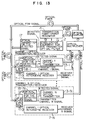
- Fig. 14 is a diagram showing a configuration of an embodiment in which a frequency stabilization system according to the present invention is applied to an optical frequency division multiplexing network.
- Figs. 15A and 15B are a diagram showing a configuration of a first embodiment of an optical frequency regulator and an optical transmitter/receiver of an optical frequency stabilization system shown in Fig. 14.
- Figs. 16A and 16B are a diagram showing a configuration of a second embodiment of an optical frequency regulator and an optical transmitter/receiver of an optical frequency stabilization system shown in Fig. 14.
- Figs. 17A and 17B are a diagram showing a third embodiment of an optical frequency regulator and an optical transmitter/receiver of an optical frequency stabilization system shown in Fig. 14.
- Figs. 18A and 18B are a diagram showing a fourth embodiment of an optical frequency regulator and an optical transmitter/receiver of an optical frequency stabilization system shown in Fig. 14.
- Figs. 19A and 19B are a diagram showing a fifth embodiment of an optical frequency regulator and an optical transmitter/receiver of an optical frequency stabilization system shown in Fig. 14.
- Figs. 20A and 20B are a diagram showing a sixth embodiment of an optical frequency regulator and an optical transmitter/receiver of an optical frequency stabilization system shown in Fig. 14.
- An optical FDM transmitter system comprises an optical FDM transmitter equipment (Fig. 1) inputted with a number N of information signals (channel 1 to N signals) for outputting an optical FDM signal, an optical fiber (designated by 1 in Fig. 1) for transmitting an optical FDM signal and an optical FDM receiver equipment (Fig. 2) inputted with an optical FDM signal for outputting signals of channels 1 to N.
- a modulation system considered for use with each optical signal includes a frequency shift keying, amplitude shift keying and a phase shift keying.
- An optical FDM transmitter equipment comprises an optical transmission filter stabilizer 2, a number N of optical transmitters 3-1 to 3-N (optical transmitters for channels 1 to N), an optical multiplexer for multiplexing optical signals outputted from the N optical transmitters and outputting an optical FDM signal, and an optical coupler for dividing an optical FDM signal into two parts.
- the component parts of the transmission optical filter stabilization equipment 2 include a standard optical source for an optical frequency signal for outputting an absolutely-stabilized optical standard frequency F0, an optical frequency modulator for subjecting the light outputted from an optical source to frequency modulation at a frequency of f0, an optical coupler for multiplexing a frequency-modulated light with an optical FDM signal and outputting it to a transmission Fabry-Perot resonator (with a transmission characteristic shown by the dashed line in Fig.
- a photo-diode for converting the light outputted from the transmission Fabry-Perot resonator into an electrical signal and producing a detected signal
- a bandpass filter (designated by BPF in the diagram with a central frequency f0) for extracting a signal component of the frequency f0 from the detected signal
- a multiplier for multiplying the extracted signal with a signal (frequency f0) from an oscillator
- a low-pass filter designated by LPF in the diagram with a cut-off frequency of f LPF « f0
- a temperature control circuit for controlling the temperature of a transmission Fabry-Perot resonator by the error signal.
- An optical frequency standard source may be realized, for example, by a configuration described in IEEE Photonics Technology Letters, Vol. 1, No. 6, pp. 140-141).
- An optical frequency modulator is realizable by using lithium niobate or the like having a photo-electric effect.
- a transmission FP resonator is realized by using, for example, such a material as synthesized quartz or BK-7. These materials have an expansion coefficient not zero against temperature changes, and therefore are capable of controlling the length of a resonator by changing the temperature thereof.
- Fig. 4 shows signal waveforms produced at various parts in the case where the transmission FP resonator is stabilized by use of the light of frequency F0 outputted from a standard optical source.
- Fig. 4A shows a voltage signal of frequency f0 applied to an optical frequency modulator.
- an optical signal central frequency F0, frequency shift ⁇ F, ⁇ F « Dop/2
- Fig. 4B an optical signal (central frequency F0, frequency shift ⁇ F, ⁇ F « Dop/2) subjected to frequency modulation is produced as an output of the optical frequency modulator (Fig. 4B).
- a transmission FP resonator having a transmission characteristic as shown in Fig. 3A and the output thereof is defected by a photo-diode, a signal as shown in Fig.
- the detected signal assumes a waveform as shown in Fig. 4D.
- This detected signal has a frequency of f0 and passes through a bandpass filter. Multiplication of a signal (frequency f0) from an oscillator produces a positive signal with a frequency of almost zero (almost direct current). When this signal is applied to a low-pass filter, a positive error signal is outputted. This error signal causes the temperature control circuit to operate in such a manner as to restore the frequency associated with a peak transmission coefficient of the transmission FP resonator from F0 + ⁇ F to F0.
- the detected signal assumes a waveform (with frequency f0 but displaced by 180 degree as compared with the waveform in Fig. 4D) as shown in Fig. 4E, thereby producing a negative error signal.
- the temperature control circuit operates in the direction opposite to Fig. 4D, and the frequency associated with a peak transmission coefficient of the transmission FP resonator is restored from F0 - ⁇ F to F0.
- the transmission characteristic of the transmission FP resonator is controlled to have a peak at a frequency F0 by the transmission Fabry-Perot resonator stabilization equipment shown in Fig. 1.
- an optical FDM signal is inputted to the transmission FP resonator in addition to an optical standard frequency f0
- the effect of the optical FDM signal can be removed by a bandpass filter (central frequency f0) if the frequency f0 is sufficiently large as compared with the transmission rate of each optical signal constituting an optical FDM signal.
- a signal similar to the one shown in Fig. 4 is obtained even when an optical FDM signal is inputted to the transmission FP resonator.
- FIG. 1 An example of configuration of a system for stabilizing the frequency of each transmission optical source for the above-mentioned transmission FP resonator is shown as an optical transmitter in Fig. 1.
- the optical transmitter includes a transmission optical source, an adder and an optical signal frequency stabilizing circuit.
- the optical transmitter for each channel has a similar configuration.
- the transmission optical source in a channel-n optical transmitter is called a transmission optical source (n).
- an optical FDM signal is inputted through the above-mentioned optical coupler to the transmission FP resonator.
- Fig. 3A The correspondence between a frequency associated with a peak transmission coefficient of the transmission FP resonator and each optical signal frequency is shown in Fig. 3A.
- a detected signal outputted from a photo-diode is distributed among the optical signal frequency stabilizing circuits in respective channel optical transmitters by being divided accordingly.
- a detected signal contains the information on frequency fluctuations of all transmission optical sources.
- a channel-1 signal is multiplied by the detected signal to extract only the information on frequency fluctuations (correlation signal) of the channel-1 transmission optical source.
- the correlation signal applied to a low-pass filter (LPF in Fig. 1, with a cut-off frequency of f LPF « transmission rate f0 of each signal) to remove high-frequency components, thus producing an error signal.
- the error signal is added to a channel-1 signal and a bias signal and is injected into the transmission optical source (1) in such a polarity that the optical frequency of the transmission optical source (1) is stabilized at a frequency F0 + Dop associated with a peak transmission coefficient of the transmission FP resonator.
- a similar operation stabilizes the transmission optical sources (2) to (N) of other channels at a peak transmission coefficient of corresponding transmission FP resonators.
- the channel-1, channel-2, ..., channel-N optical signal frequencies are stabilized at F0 + Dop, F0 + 2Dop, ...., F0 + NDop, respectively.
- This stabilization method is described, for example, in Electronics Letters, Vol. 23, No. 14, pp. 750-752.
- An optical FDM receiver equipment includes a receiving optical filter, a receiving optical filter stabilization equipment (designated by numeral 6 in Fig. 2), a number N of heterodyne optical receivers (channel-1 to channel-N heterodyne optical receivers) (designated by numeral 7 in Fig. 2), and an optical demultiplexer for dividing the optical DM signal into a number N of heterodyne optical receivers.
- a receiving optical filter stabilization equipment is identical to that of a transmission Fabry-Perot resonator stabilization equipment in the optical FDM transmitter equipment.
- An optical multiplexer is added to the transmission Fabry-Perot resonator stabilization equipment because the local optical signal outputted from each heterodyne optical receiver is multiplexed and applied to the receiving Fabry-Perot resonator.
- a Mach-Zehnder optical filter or a star coupler may be used as an optical multiplexer.
- a channel-1 heterodyne optical receiver includes a local signal optical source for outputting a local optical signal of F0 + Dop + f IF in optical frequency, an optical coupler for dividing a local optical signal, a polarization diversity optical receiver for receiving an optical signal and producing a base band signal by use of one output of the optical coupler, a decision and regeneration circuit for discriminating and regenerating a channel-1 signal from the signal outputted from the polarization diversity optical receiver, and a local frequency stabilization circuit for producing an error signal from a detected signal obtained in the receiving Fabry-Perot resonator stabilization equipment.
- the local frequency stabilization circuit includes a bandpass filter (BPF with a central frequency f1) for extracting the components of frequency f1 from the detected signal, an oscillator (with frequency f1 identical to the central frequency of the bandpass filter) for outputting a sinusoidal wave signal, a multiplier for multiplying an extracted signal with a sinusoidal signal, a low-pass filter (LPF with a cut-off frequency of f LPF « f1) for extracting an error signal from a multiplied signal, and an adder for adding an error signal, a sinusoidal signal and a bias signal to each other.
- BPF bandpass filter
- LPF low-pass filter
- the heterodyne optical receiver for each channel has a similar configuration, although the central frequencies of the oscillator and the bandpass filter are f1, f2 Vietnamese, f N and are different for different channels 1, 2, owing, N respectively (f1 ⁇ f2 ⁇ Vietnamese ⁇ f N ⁇ f0). Also, the local optical source in a channel-n heterodyne optical receiver is called a local optical source (n).
- the above-mentioned polarization diversity optical receiver is realized with a configuration described in IEEE, Journal of Lightwave Technology, Vol. LT-5, No. 2, pp. 274-276.
- a heterodyne optical receiver is such that a local optical source is subjected to frequency modulation by a minute sinusoidal wave current in order to stabilize the optical frequencies of local optical sources ((1) to (N)) of channels 1, 2, ...., N to peak transmission coefficient frequencies (F0 + Dop + f IF , F0 + Dop + 2f IF , ...., F0 + Dop + Nf IF ) corresponding to the receiving FP resonators, respectively.
- Modulation frequencies f1, f2 ...., f N (f1 ⁇ f2 ⁇ ... ⁇ f N ⁇ f0) are allocated to channels 1, 2, ...., N, respectively.
- Fig. 5A shows a waveform of a modulation current.
- Fig. 5B an optical signal subjected to frequency modulation around a frequency F0 + Dop + f IF is produced (Fig. 5B).
- This optical signal is applied to a receiving FP resonator having a transmission characteristic as shown by the dashed line in Fig. 3A, and the output thereof is detected by a photo-diode, thus producing a detected signal as shown in Fig. 5C.
- This waveform is produced because the receiving FP resonator has a peak transmission coefficient at a frequency F0 + Dop + f IF , and the optical power outputted from the receiving FP resonator becomes maximum each time the optical frequency of the frequency-modulated signal coincides with F0 + Dop + f IF . At the same time, the frequency of detected signal variations becomes 2f1. This detected signal is therefore removed by a bandpass filter. As a result, the error signal outputted from the low-pass filter becomes zero and the local optical source (1) is maintained at a constant frequency.
- the detected signal assumes a waveform as shown in Fig. 5D.
- This detected signal has a frequency f1 and passes through a bandpass filter, and by multiplication with a signal (f1) from an oscillator, generates a positive signal with a frequency of almost zero (direct current). As a consequence, a positive error signal is produced from a low-pass filter. This error signal restores the frequency of the local optical source (1) to F0 + Dop + f IF .
- the detected signal assumes a waveform shown in Fig. 5E thereby to produce a negative error signal.
- the frequency of the local optical source (1) is thus restored from F0 + Dop + f IF + ⁇ F to F0 + Dop + f IF .
- the receiving FP resonator is supplied with lights from other local optical sources (2) to (N) in addition to the light from the local optical source (1), the fact that these lights are subjected to frequency modulation with different frequencies makes it possible to extract only the information on fluctuations of related local optical source frequencies through a bandpass filter (BPF) of each heterodyne optical receiver. More specifically, even when other lights are inputted to the receiving FP resonator, a signal waveform similar to the one shown in Fig. 5 is capable of being produced.
- BPF bandpass filter
- the optical frequencies of the local optical sources of channels 1, 2, arranged, N of a heterodyne optical receiver are stabilized to F0 + Dop + f IF , F0 + 2Dop + f IF , ...., F0 + NDop + f IF , respectively.
- FIG. 6 A configuration of a second embodiment of an optical FDM receiver equipment is shown in Fig. 6.
- the second embodiment is an improvement of an optical FDM receiver equipment according to the first embodiment for application to an optical FDM transmission system of information distribution type.
- the optical FDM signal obtained in an optical FDM transmitter equipment (with the same configuration as in Fig. 1) is distributed among tunable optical FDM receiver equipments arranged at different positions through different optical fibers.
- the optical FDM receiver equipment is adapted to receive a channel of the desired optical signal from among optical FDM signals sent thereto.
- the frequency of a local optical source is required to be switched in order to switch the channels of optical signals received.
- a tunable heterodyne optical receiver is installed at the receiving end.
- the optical FDM receiver equipment includes a receiving optical filter, a receiving optical filter stabilization equipment and a tunable heterodyne optical receiver (designated by numeral 11 in Fig. 6).
- the receiving optical filter stabilization equipment is configured as described by numeral 10 in Fig. 6, with an optical coupler removed from the equipment 6 according to the first embodiment. This is because the optical receiving equipment under consideration includes only a single local optical source.
- the receiving Fabry-Perot resonator is stabilized to an optical standard frequency F0 by the same method as according to the first embodiment.
- the present embodiment is different from the first embodiment in that according to the present embodiment, the frequency of the local optical source is switched in accordance with the channel of an optical signal received.
- Numeral 11 designates a configuration of a tunable heterodyne optical receiver. This configuration constitutes a heterodyne optical receiver 7 shown in Fig. 2 with an optical tuner 13 added thereto. Also, a switch 14 is added to the local frequency stabilization circuit 12.
- the optical tuner includes a low-pass filter (LPF, with a cut-off frequency of f1', f1' ⁇ f1), a pulse counter for counting the pulses generated as a detected signal at the time of switching the local frequency, a comparator for comparing the number of counted pulses with the number of pulses that should have been generated at the time of channel switching (which depends on the channel requested), and a controller for turning on and off a switch and controlling the frequency of a tunable local optical source in accordance with the output of the comparator.
- LPF low-pass filter
- a pulse counter for counting the pulses generated as a detected signal at the time of switching the local frequency
- a comparator for comparing the number of counted pulses with the number of pulses that should have been generated at the time of channel switching (which depends on the channel requested)
- a controller for turning on and off a switch and controlling the frequency of a tunable local optical source in accordance with the output of the comparator.
- Fig. 7 shows the transmission characteristic of a receiving FP resonator and an arrangement of local frequencies before and after frequency switching.
- the transmission characteristic of the receiving FP resonator is identical to that in the first embodiment, and is stabilized in such a manner that the transmission coefficient reaches a peak at an optical standard frequency F0.
- the local frequency is switched from F0 + Dop + f IF to F0 + NDop + f IF in order to switch the receiving signal from channel 1 to channel N.
- the receiving FP resonator has transmission coefficient peaks in the number of 4(N - 1) - 1 between frequencies F0 + Dop + f IF and F0 + NDop + f IF (except for the transmission coefficient peaks at the frequencies of starting and terminating points).
- a pulse is generated in the detected signal outputted from the receiving FP resonator each time the local frequency passes a transmission coefficient peak.
- the correspondence between the pulse generation, switch on/off states and the local frequency is shown in Fig. 8.
- Fig. 8A is a diagram showing whether the switch is in on or off state.
- a channel request signal When a channel request signal is applied to an optical tuner with the aim to switching the channel to N while the channel 1 is received, the switch is turned off and the local frequency stabilization to a frequency associated with a peak transmission coefficient is stopped. Then, as shown in Fig. 8B, the local frequency is swept from F0 + Dop + f IF toward F0 + NDop + f IF . In the sweeping process, a pulse shown in Fig. 8C is generated in the detected signal. A pulse counter counts the pulses thus generated, and the local frequency stops being swept with the pulse immediately following the time point when the number of pulses reaches 4(N - 1) - 1.
- the switch is then turned on again, and the local frequency is stabilized at a frequency associated with a peak transmission coefficient of the receiving FP resonator at F0 + NDop + f IF . Since the channel-N optical signal frequency is F0 + NDop, the intermediate frequency of the signal obtained by heterodyne detection is f IF , so that the receiving of channel N is immediately started (tuning completed).
- the optical frequency of a local optical source is stabilized after being switched to F0 + Dop + f IF , F0 + 2Dop + f IF , ...., F0 + (N - 1)Dop + f IF , respectively, thereby making it possible to start receiving immediately.
- the local frequency is controlled within an optical FDM receiver equipment, the advantage results that the local frequency continues to be controlled in stable manner even when the optical FDM signal is not applied to an optical receiving equipment. Further, a tuning error is avoided even if a given channel is missed in an optical FDM signal.
- Fig. 9A shows two transmission systems connected in cascade according to the present invention capable of transmitting an N-channel signal. This configuration permits the total transmission distance to be lengthened as compared with the case where a single transmission system is used. The total transmission distance can also be lengthened by increasing the number of units connected (to three or more) or by connecting an optical amplifier to an optical fiber.
- Fig. 9B shows a case in which a transmission system capable of transmitting a number m of channels (1 to m), and a transmission system capable of transmitting (N - m) channels (m+1 to N) in the latter stages of the transmission system according to the present invention capable of transmitting an N-channel signal.
- This configuration makes it possible to divide N channels and transmit parts thereof to different places. Assuming, for example, that an optical FDM receiver equipment of a transmission system capable of transmitting a number m of channels and an optical FDM receiver equipment capable of transmitting (N - m) channels are arranged at different places, signals of channels 1 to m and those of channels m+1 to N can be transmitted to different places. If the method of dividing channels and the number of divisions are changed, the number of places to which transmission is made is increased. Also, if the configuration of Fig. 9A is combined with that shown in Fig. 9B, the required channel can be transmitted divided to different places very far from each other. Fig.
- FIGC shows a transmission system according to a second embodiment connected in the latter stages of the transmission system according to the first embodiment of the present invention.
- an N-channel signal can be distributed among a plurality of different places.
- an N-channel signal can be distributed among a plurality of places very far from each other, if the configurations shown in Figs. 9A, B and C are combined with each other.
- the transmission distance can be lengthened even more by connecting an optical amplifier to the optical fiber.
- the optical FDM transmitter equipment and the optical FDM receiver equipment other than those at the sending end are replaced, in whole or in part, by an optical amplifier in Figs. 9A to C, the optical FDM transmission system can be further simplified.
- the present invention is not limited to the above-mentioned embodiments.
- the transmission and receiving Fabry-Perot resonators are not necessarily required to have a transmission characteristic specified in Fig. 3.
- An example is shown in Fig. 10.
- the local optical signal 1 is stabilized to an optical frequency associated with a peak transmission coefficient of a transmission Fabry-Perot (FP) resonator, the local optical signal 2 to an optical frequency associated with other than a peak or minimum transmission coefficient, and the local optical signal 3 to an optical frequency associated with a minimum transmission coefficient.
- the stabilization to an optical frequency associated with other than a peak or minimum transmission coefficient of the FP resonator is realized by controlling the error signal to approach not zero but a reference voltage other than zero.
- the stabilization to an optical frequency associated with a minimum transmission coefficient is achieved, for example, by reversing the polarity of an error signal of a receiving optical filter stabilization equipment in Fig. 2. Specifically, a similar effect is obtained to the extent that the transmission coefficient of the FP resonator in the transmitter and receiver equipment is stabilized by an optical standard frequency and at the same time the frequencies of the transmission optical source and the local optical sources in the transmitter and receiver equipment are stabilized with reference to the transmission coefficient of an optical filter. Also, even when the frequency of an optical source for the optical standard frequency is different between the transmitter and receiver equipment, an effect similar to that of the above-mentioned embodiment is obtained as long as the respective frequencies are known.
- N 1, i.e., even when an FDM transmission is not involved, on the other hand, a similar effect is obtained.
- the transmission rate may be varied from one channel to another.
- the purpose is served as long as the intermediate frequency obtained at a heterodyne optical receiver is substantially coincident with a design value.
- a similar effect is obtainable also by use of an optical filter of Mach-Zehnder type in place of an FP resonator.
- a method other than mentioned above may be used for stabilization of the optical signal frequency in an optical FDM transmitter equipment.
- an oscillator and a bandpass filter different in frequency as in the case of optical FDM receiver equipment may be installed in each optical transmitter to stabilize the optical signal frequency on the same principle as in the optical FDM receiver equipment.
- the optical multiplexer and the optical demultiplexer used in the optical FDM transmitter and receiver equipment may be either an optical star coupler or a combination of an optical multiplexer/demultiplexer and an optical star coupler.
- both the signal frequency and the local frequency are stabilized to a frequency level associated with a peak transmission coefficient of an FP resonator, it may not necessarily be stabilized to a frequency associated with a peak transmission coefficient. Instead, the frequency to which stabilization is made may be the one associated with a minimum transmission coefficient or an appropriate frequency point between peak and minimum transmission coefficients.
- the purpose is served if the difference between an optical signal frequency and a local frequency is equal to the desired intermediate frequency f IF . This is also the case with the relation between an optical standard frequency and the transmission coefficient of an FP resonator.
- the optical source for the optical standard frequency may alternatively be directly modulated to produce a frequency-modulated light.
- the optical source for the optical standard frequency is a semiconductor laser
- a frequency-modulated light is obtainable by modulating a current injected into the semiconductor laser.
- An example of configuration of a transmission optical filter stabilization equipment used for direct modulation of an optical source is shown in Fig. 11.
- an optical filter at the sending end may be used as an optical multiplexer in an optical FDM transmitter equipment at the same time.
- This sharing is realized by using an optical filter of Mach-Zehnder type at the sending end.
- An example of configuration of the optical FDM transmitter equipment in the case of shared use is shown in Fig. 11.
- the transmission optical filter stabilization equipment (designated by 15 in Fig. 11) and the optical transmitters are configured the same way as in Fig. 1.
- the optical coupler in the transmission optical filter stabilization equipment is eliminated, and the output light from each optical transmitter is applied to an optical filter of Mach-Zehnder type (designated by 16 in Fig. 11).
- the optical FDM signal outputted from an optical filter is divided into two branches, one being sent to an optical fiber and the other to a photo-diode in the transmission filter stabilization equipment thereby to stabilize each optical signal frequency on the same principle as in Fig. 1.
- the optical FDM transmitter equipment is simplified as compared with Fig. 1.
- the optical FDM receiver equipment can be simplified as compared with Fig. 2 or 6 by being configured in such a manner that a multiplexer for multiplexing a plurality of local optical signals is used as an optical filter at the receiving end at the same time.
- an optical signal frequency and a local frequency are controlled (stabilized and tuned) independently of each other at an optical FDM transmitter equipment and an optical receiver equipment respectively, and therefore the local frequency can continue to be controlled in stable manner even when an optical signal fails to be applied to an optical FDM receiver equipment due to such causes as the breakage of an optical fiber or a fault of the transmission light source.
- Fig. 12 shows an embodiment involving such a case.
- a detected signal optical transmitter 17 for producing a detected signal converted into an optical signal (optical detected signal) is applied to an optical FDM transmitter equipment on the one hand and a detected signal optical receiver 18 for receiving an optical detected signal is installed in an optical transmitter of each channel on the other hand.
- the other parts of the configuration are identical to those in Fig. 1.
- Another advantage of this configuration is that information supplied from a remote place can be multiplexed to produce an optical FDM signal.
- Fig. 13 Another embodiment providing an improvement of the above-mentioned embodiment is shown in Fig. 13.
- the optical transmitter of each channel includes a heterodyne optical receiver 7 shown in Fig. 2 to constitute an optical transmitter/receiver.
- each optical transmitter/receiver for demultiplexing an optical detected signal, resulting in the advantage that the optical fiber that has so far been used only for transmission of an optical detected signal can be used also for transmission of an optical FDM signal at the same time.
- the above-mentioned heterodyne optical receiver may of course be replaced with equal effect by an optical receiver of direct detection type with a tunable optical filter.
- the use of an optical transmitter/receiver as shown in Fig. 13 realizes a system or a network configuration other than shown in Fig. 9. An example is shown in Fig. 14.
- Fig. 14 shows a configuration of an embodiment in which a frequency stabilization system according to the present invention is applied to an optical network of optical frequency division multiplexing type.
- a plurality of optical transmitter/receivers 1401, 1402, 1403 and an optical frequency regulator 1404 are connected in loop by an optical fiber 1405.
- Each of the optical transmitter/receivers 1401, 1402, 1403 has a laser providing an optical source of a specific frequency.
- the embodiment shown in Fig. 14 represents a case in which a single optical frequency regulator 1404 is included in the network, a plurality of optical frequency regulators may be constructed in the network.
- the optical network according to this embodiment is of an optical frequency division multiplexing type, the frequencies of optical signals outputted from the optical transmitter/receivers 1401, 1402, 1403 are different from each other.
- the function of the optical frequency regulator 1404 is to stabilize the optical frequency of the optical sources of the optical transmitter/receivers 1401, 1402, 1403 to a regulated value in order to prevent the interference between the three optical signals.
- the optical frequency regulator 1404 internally determines three stable regulated optical frequencies different from each other.
- the optical frequency regulator 1404 receives a part of the optical signals from the optical transmitter/receivers 1401, 1402, 1403 connected by the optical fiber 1405, and determines the deviation between the frequencies of the three optical signals and corresponding regulated optical frequencies respectively. These values of deviation are carried on an optical signal (by subjecting an optical signal to frequency modulation with the deviation value, or otherwise) and are transmitted to the corresponding optical transmitter/receivers 1401, 1402, 1403 through the optical fiber 1405.
- the optical transmitter/receivers 1401, 1402, 1403 select deviation values associated therewith respectively from a plurality of deviation values contained in the optical signal received from the optical frequency regulator 1404, and correct the frequencies of the respective optical sources in such a manner as to obtain a deviation of 0 or a predetermined value.
- This series of operations stabilize the frequencies of the optical signals produced by the optical transmitter/receivers 1401, 1402, 1403 in conformity with or with a predetermined offset from the regulated optical frequency determined by the optical frequency regulator 1404.
- each value of deviation may be transmitted to each optical transmitter/receiver by use of an electrical signal instead of an optical signal.
- the optical frequency regulator 1404 and each of the optical transmitter/receivers 1401, 1402, 1403 may be connected only by electric wires apart from the configuration shown in Fig. 14. Also, the optical frequency regulator 1404 and the optical transmitter/receivers 1401, 1402, 1403 may be coupled not in loop but in star.
- the deviation between the value of a regulated optical frequency in the optical frequency regulator 1404 and the frequency of the optical signal outputted from each optical transmitter/receiver is determined at the optical frequency regulator 1404 and is transmitted to the optical transmitter/receivers 1401, 1402, 1403, which in turn correct the optical frequencies of their own optical sources accordingly.
- the system may comprise means for transmitting the optical signal itself of a regulated optical frequency internally determined by the optical frequency regulator 1404, directly to the corresponding optical transmitter/receivers 1401, 1402, 1403, so that the optical transmitter/receivers may detect the deviation between the optical signal thus sent and their own optical signals respectively and control their own optical frequencies in such a manner as to keep the deviation frequency at zero or a predetermined value.
- each optical transmitter/receiver includes a single transmission optical source in each optical transmitter/receiver
- the optical frequencies of a plurality of transmission optical sources which may be provided in each optical transmitter/receiver may be regulated in exactly the same manner by means of a frequency regulator.
- the optical frequency of a local optical source included in the receiving section of each optical transmitter/receiver which is not described above, may be regulated by a frequency regulator in similar fashion.
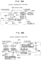
- Fig. 15 is a diagram showing a configuration of a first embodiment of the optical transmitter/receiver and the optical frequency regulator in the optical frequency stabilization system shown in Fig. 14.
- Fig. 15A shows a configuration of an optical transmitter/receiver and Fig. 15B an optical frequency regulator.
- the deviation between the actual optical frequency of an optical source of each of the optical transmitter/receivers 1401 to 1403 and that of each optical transmitter/receiver regulated by the optical frequency regulator is transmitted to each optical transmitter/receiver by use of an optical signal from an optical frequency regulator 1404.
- the laser 1509 in the optical transmitter 1502 of the optical transmitter/receiver has the optical frequency thereof regulated by the control circuit 1506 in such a manner as to be differentiated from the optical frequency of the laser of the remaining optical transmitter/receivers. Also, the laser 1509 is modulated by a data i1508 providing information to be transmitted, and is further subjected to fine frequency modulation by a signal 1507 of a frequency fi specific to the optical transmitter/receiver. The optical signal outputted from the laser 1509 is led to an optical network by the optical fiber 1501.
- the optical frequency regulator 1404 shown in Fig. 15B includes an optical resonator 1520 made up of a Fabry-Perot resonator having a periodic transmission characteristic on the optical frequency axis.
- an optical resonator 1520 made up of a Fabry-Perot resonator having a periodic transmission characteristic on the optical frequency axis.
- a plurality of frequencies associated with an optical signal which is transmitted through the optical resonator 1520 and has a maximum intensity are used as regulated optical frequencies of the optical transmitter/receivers 1401, 1402, 1403.
- frequencies associated with an optical signal intensity reflected on the optical resonator 1520 and having a minimum value may be employed as regulated optical frequencies.
- a part of the optical frequency division multiplexing signal sent from the optical transmitter/receivers 1401, 1402, 1403 by the optical fiber 1501 is applied to the optical resonator 1520, and after being converted into an intensity signal, is detected by an optical detector 1521.
- This synchronous detection is effected by a timing control circuit 1525 in time division.
- An output signal 1526 from the mixer 1523 makes up a deviation between the frequency fi of an optical signal outputted from the i-th optical transmitter/receiver and the resonance frequency of the optical resonator 1520 corresponding to the optical frequency fi.
- the laser 1528 is modulated by the deviation signal 1526 through the control circuit 1527, and the deviation data is transmitted as an optical signal to each of the transmitter/receivers 1401, 1402, 1403 through the optical fiber 1501.
- the laser 1528 is subjected to intensity modulation by a signal of a frequency Fi in advance.
- the optical transmitter/receiver receives a part of the optical signal holding the above-mentioned deviation data sent from the optical fiber 1501 and intensity-modulated by the signal of frequency Fi.
- the signal thus received is divided into two parts, one being sent to the optical receiver 1503, and the other to the optical transmitter 1502.
- the optical signal received by the optical transmitter 1502 is converted into an electrical signal by the optical detector 1504.
- This electrical signal contains a deviation signal of the transmitter/receiver.
- a deviation signal subjected to intensity modulation at Fi is taken out by use of a bandpass filter 1505.
- the control circuit 1506 corrects the optical frequency of the laser 1509.
- optical frequency of the laser 1509 of the transmitter 1502 of each optical transmitter/receiver causes the optical frequency of the laser 1509 of the transmitter 1502 of each optical transmitter/receiver to coincide with a given resonance frequency of the optical resonator 1520.
- the coincidence between the optical frequency of the laser of each optical transmitter/receiver with adjacent resonant frequencies of the optical resonator 1520 makes it possible to secure equal channel intervals.
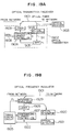
- Fig. 16 is a diagram showing a configuration of a second embodiment of the optical transmitter/receiver and the optical frequency regulator of the optical frequency stabilization system shown in Fig. 14.
- Fig. 16A shows a configuration of the optical transmitter/receiver, and the Fig. 16B that of the optical frequency regulator.
- the optical frequency regulator in order to send the deviation value from the optical frequency regulator while discriminating the optical transmitter/receiver, the optical frequency regulator is synchronized with each optical transmitter/receiver thereby to transmit an optical signal carrying the deviation data in time division.
- the sync signal resulting from the modulation of the laser 1628 with the signal 1629 from the timing control circuit 1625 shown in Fig. 16B is applied through the optical fiber 1601 to each optical transmitter/receiver.
- the optical detector 1604 shown in Fig. 16A converts an optical signal into an electrical signal
- the sync detector 1605 detects the sync signal 1629.
- the control circuit 1606, during its own transmission time subjects the laser 1609 to fine frequency modulation with the signal 1607 of frequency f on the basis of a detected sync signal, and applies an optical signal to the optical fiber 1601.
- This optical signal is transmitted through the optical resonator 1620 as shown in Fig. 16B and is converted into an electrical signal.
- This electrical signal 1622 is subjected to synchronous detection by the signal 1624 of frequency f.
- the laser 1628 is modulated with a deviation signal 1626 and transmitted to the optical transmitter/receiver. In this configuration, there is only one laser in the optical transmitter/receiver which is frequency-modulated with frequency f at a given time point, and only the particular laser 1609 in the optical transmitter/receiver is corrected.
- Fig. 17 is a diagram showing a configuration of a third embodiment of the optical transmitter/receiver and the optical frequency regulator of the optical frequency stabilization system shown in Fig. 14.
- Fig. 17A shows a configuration of an optical transmitter/receiver, and Fig. 17B that of an optical frequency regulator.
- a header specific to each optical transmitter/receiver is attached to the optical signal carrying the deviation value.
- an optical signal outputted from the laser 1728 of the optical frequency regulator contains a header for discriminating each optical transmitter/receiver as well as the deviation value thereof.
- Each optical transmitter/receiver takes in only a deviation sent with an optical signal carrying a header specific to itself detected by a header detector 1705 from the output of the optical detector 1704 as shown in Fig. 117A, thereby correcting the optical frequency of the laser 1709.
- the wavelength band of an optical signal for transmitting the data i1708 is differentiated from that of an optical signal for transmitting the deviation.
- the lasers 1709 and 1728 belong to wavelength bands different from each other.
- the use of a demultiplexer 1710 makes it possible to isolate a received optical signal into the optical transmitter 1702 and the optical receiver 1703. In the configuration shown in Fig.
- the signal f i 1707 of the control circuit 1706 and the signal 1708 of the data i correspond to the signal f i 1507 of the control circuit 1506 and the data i signal 1508 respectively
- the mixer 1723, the timing control circuit 1725, the signal 1726 and the control circuit 1727 correspond respectively to the mixer 1523, the timing control circuit 1525, the signal 1526 and the control circuit 1527.
- the optical resonator 1720 shown in Fig. 17B is controlled in such a manner as to resonate at the optical frequency of the standard light 1730.
- This control makes it possible to connect a plurality of optical networks having a plurality of optical transmitter/receivers to each other. Specifically, if a plurality of optical resonators having the same characteristic are controlled to resonate at the frequency of a standard light shared by them by an optical frequency regulator in an optical network, then the frequencies of optical signals outputted from the optical transmitter/receivers in a plurality of optical networks can be integrally controlled.
- the standard light 1730 is frequency-modulated in advance by use of the signal source 1731 of frequency f.
- the output signal from the optical detector 1721 is applied to the mixer 1732 with the signal of the signal source 1731 thereby to produce a signal for controlling the optical resonator 1720.
- This signal corresponds to a relative deviation of a resonance frequency of the optical resonator 1720 for the optical frequency of the standard light 1731.
- this signal is negatively fed back to the optical resonator 1720, one of the resonance frequencies of the optical resonator 1720 comes to coincide with the optical frequency of the standard light 1730.
- Fig. 18 is a diagram showing a configuration according to a fourth embodiment of the optical transmitter/receiver and the optical frequency regulator of the optical frequency stabilization system shown in Fig. 14.
- Fig. 18A shows a configuration of the optical transmitter/receiver and Fig. 18B a configuration of the optical frequency regulator.
- a plurality of deviation values corresponding to a plurality of optical transmitter/receivers from the optical frequency regulator are transmitted to the respective optical transmitter/receivers by being carried on optical signals of different optical frequencies.
- the optical frequency regulator has as many lasers 1828-1, ...., 1828-n with different optical frequencies as the optical transmitter/receivers as shown in Fig. 18B.
- the lasers 1828-1, ...., 1828-n are controlled respectively by the control circuits 1827-1, ...., 1827-n, which in turn are energized by the outputs of mixers 1823-1, ...., 1823-n supplied with the outputs of the optical detector 1821 and the frequency signals f1, ...., f n from the synchronous detection signal generator 1825.
- Each optical transmitter/receiver receives only an optical signal carrying its own deviation value by use of an optical filter 1811. According to the present embodiment, a number n of deviation values can be transmitted at a time.
- the optical fiber 1801, the optical transmitter 1802, the optical receiver 1803, the optical detector 1804, the control circuit 1806, the frequency signal fi1807, the data i1808, the laser 1809 and the demultiplexer 1810 of the optical transmitter/receiver correspond to the optical fiber 1701, the optical transmitter 1702, the optical receiver 1703, the optical detector 1704, the control circuit 1706, the frequency signal f i 1707, the data i1708, the laser 1709 and the demultiplexer 1710 in Fig. 17, respectively.
- the functions and configurations of the optical resonator 1820, the optical detector 1821, the standard light 1830, the signal source 1831 and the mixer 1832 of the optical frequency regulator are identical to those of the optical resonator 1720, the optical detector 1721, the standard light 1730, the signal source 1731 and the mixer 1732 in Fig. 17, respectively.
- the embodiment of Fig. 18 may be configured of a single laser by integrating a plurality of lasers 1828-1, ...., 1828-n. Specifically, the illuminance frequency is changed by changing the temperature, current, etc. of the laser to send a deviation. In this case, a plurality of deviation values are transmitted in time division.
- Fig. 19 is a diagram showing a configuration of each part of the optical frequency stabilization system shown in Fig. 14 according to a fifth embodiment.
- Fig. 19A shows a configuration of an optical transmitter/receiver, and Fig. 19B that of an optical frequency regulator.
- optical signals of a plurality of regulated frequencies determined by the optical frequency regulator are transmitted to the respective optical transmitter/receivers, which correct the optical frequencies of their respective lasers in such a manner that the deviation between the respective received optical signals and the optical signals of the respective lasers assume zero or a predetermined value.
- This embodiment is such that in order to generate optical signals of a plurality of regulated frequencies by the optical frequency regulator, the temperature, current, etc. of the laser are changed.
- only an optical signal of a single regulated frequency can be transmitted at a time.
- a part of the optical signals of the laser 1928 in the optical frequency regulator is introduced to the optical resonator 1920.
- the optical frequency of the laser 1928 is swept by the temperature/current control circuit 1927.
- the light transmitted through the optical resonator 1920 is detected by the optical detector 1921.
- the signal 1922 thus detected is applied to the temperature/current control circuit 1927 and the timing control circuit 1925.
- the optical frequency of the laser 1928 coincides with the resonance frequency of the optical resonator 1920, the signal transmitted through the optical resonator 1920 increases, thereby increasing the detected signal 1922.
- the sweeping of the laser 1928 is stopped by the timing control circuit 1925.
- the optical frequency of the laser 1928 at this time point is defined as the optical frequency of the i-th transmitter.
- This optical signal is subjected to intensity modulation with the signal 1927 of frequency Fi from the timing control circuit 1925 by an intensity modulator 1929 and sent out to the network by the optical fiber 1901. After that, the sweeping of the optical frequency of the laser 1928 is started and continued until it comes to coincide with the next resonance frequency.
- the optical signal sent from the network is introduced partly to the optical receiver 1902 and partly to the optical transmitter 1902.
- the optical detector 1904 of the optical transmitter 1902 detects the laser 1928 and the optical signal from a related laser 1909.
- the optical detector 1904 Upon receipt of an intensity-modulated optical signal with frequency Fi from the optical frequency regulator, the optical detector 1904 detects the deviation (beat) signal 1911 and the laser 1909.
- the optical frequency of the laser 1909 is corrected by the temperature/current control circuit 1908 in such a manner that the beat signal 1911 becomes zero or a predetermined value.
- a bandpass filter 1905 of a pass bandwidth Fi is prepared in order to prevent the erroneous operation at an optical frequency setting signal for the transmitters of the other optical transmitter/receivers.
- a signal is outputted only when the beat signal 1911 contains a component of frequency Fi, and the temperature/current control circuit 1908 is operated only in that case.
- the optical frequency intensity-modulated with frequency Fi sent from the network should be made to coincide with the optical frequency of the laser 1909. This embodiment facilitates the system initiation and permits automatic start.
- an optical signal of a regulated optical frequency can be transmitted to all the optical transmitter/receivers at the same time, if lasers as many as the optical transmitter/receivers are prepared.
- Fig. 20 is a diagram showing a configuration of each part of the optical frequency stabilization system shown in Fig. 14 according to a sixth embodiment.
- Fig. 20A shows a configuration of an optical transmitter/receiver
- Fig. 20B that of an optical frequency regulator.
- the intensity modulator 1929 and the signal 1927 of frequency Fi of the optical frequency regulator are eliminated from the configuration of the embodiment shown in Fig. 19, and the bandpass filter 1905 is replaced by a sync detector 2005 for detecting a sync signal 2011 in the optical transmitter/receiver.
- a sync detector 2005 for detecting a sync signal 2011 in the optical transmitter/receiver.
- the optical frequency regulator is synchronized with each optical transmitter/receiver to send a regulated optical frequency to each optical transmitter/receiver, thus eliminating the intensity modulator from the optical frequency regulator.
- the optical fiber 2001, the optical transmitter 2002, the optical receiver 2003, the detector 2004, the temperature/current control circuit 2006, the data i signal 2008 and the laser 2009 of the optical transmitter/receiver correspond to the optical fiber 1901, the optical transmitter 1902, the optical receiver 1903, the detector 1904, the temperature/current control circuit 1906, the data i signal 1908 and the laser 1909, respectively.
- the output signal 2022 of the detector 2021 of the optical frequency regulator, the timing control circuit 2025, the temperature/current control circuit 2027 and the laser 2028 correspond to the output signal 1922 of the detector 1921, the timing control circuit 1925, the temperature/current control circuit 1927 and the laser 1928 shown in Fig. 19, respectively.
- the functions and configuration of the optical resonator 2020, the standard light 2030, the signal source 2031 and the mixer 2032 of the optical frequency regulator are similar to those of the optical resonator 1720, the standard light 1730, the signal source 1731 and the mixer 1732 shown in Fig. 17, respectively.
Priority Applications (1)
| Application Number | Priority Date | Filing Date | Title |
|---|---|---|---|
| EP97115846A EP0814578A3 (de) | 1991-07-05 | 1992-07-03 | Optischer Frequenzmultiplexsender |
Applications Claiming Priority (4)
| Application Number | Priority Date | Filing Date | Title |
|---|---|---|---|
| JP3165360A JPH0514280A (ja) | 1991-07-05 | 1991-07-05 | 光周波数分割多重伝送装置 |
| JP165360/91 | 1991-07-05 | ||
| JP32435391A JP3246930B2 (ja) | 1991-12-09 | 1991-12-09 | 光周波数安定化方式 |
| JP324353/91 | 1991-12-09 |
Related Child Applications (1)
| Application Number | Title | Priority Date | Filing Date |
|---|---|---|---|
| EP97115846.4 Division-Into | 1997-09-11 |
Publications (3)
| Publication Number | Publication Date |
|---|---|
| EP0521514A2 true EP0521514A2 (de) | 1993-01-07 |
| EP0521514A3 EP0521514A3 (en) | 1994-09-21 |
| EP0521514B1 EP0521514B1 (de) | 1998-04-08 |
Family
ID=26490123
Family Applications (2)
| Application Number | Title | Priority Date | Filing Date |
|---|---|---|---|
| EP97115846A Withdrawn EP0814578A3 (de) | 1991-07-05 | 1992-07-03 | Optischer Frequenzmultiplexsender |
| EP92111277A Expired - Lifetime EP0521514B1 (de) | 1991-07-05 | 1992-07-03 | Optisches Übertragungssystem mit Frequenzmultiplexierung |
Family Applications Before (1)
| Application Number | Title | Priority Date | Filing Date |
|---|---|---|---|
| EP97115846A Withdrawn EP0814578A3 (de) | 1991-07-05 | 1992-07-03 | Optischer Frequenzmultiplexsender |
Country Status (3)
| Country | Link |
|---|---|
| US (1) | US5408349A (de) |
| EP (2) | EP0814578A3 (de) |
| DE (1) | DE69225024T2 (de) |
Cited By (3)
| Publication number | Priority date | Publication date | Assignee | Title |
|---|---|---|---|---|
| EP0607029A2 (de) * | 1993-01-14 | 1994-07-20 | Nippon Telegraph And Telephone Corporation | Optisches bidirektionales Kommunikationssystem mit Wellenlängenmultiplex |
| US5510922A (en) * | 1994-06-28 | 1996-04-23 | Fujitsu Limited | Optical frequency stabilizer and optical frequency selector |
| EP0829935A2 (de) * | 1996-08-14 | 1998-03-18 | Kokusai Denshin Denwa Kabushiki Kaisha | Optischer Frequenzstabilisator |
Families Citing this family (31)
| Publication number | Priority date | Publication date | Assignee | Title |
|---|---|---|---|---|
| JPH06224882A (ja) * | 1992-10-03 | 1994-08-12 | Canon Inc | 光fsk受信器及びそれを用いた光fdm−fsk伝送システム |
| JP3303515B2 (ja) * | 1994-03-18 | 2002-07-22 | キヤノン株式会社 | 光通信方式及びそれを用いた光通信システム |
| JPH08316938A (ja) * | 1995-05-17 | 1996-11-29 | Canon Inc | 複数のチャンネルを多重して通信を行う光通信方法及び光通信システム |
| US5717708A (en) * | 1995-11-09 | 1998-02-10 | Mells; Bradley | Method and apparatus of stabilizing a semiconductor laser |
| JP3720112B2 (ja) | 1996-03-18 | 2005-11-24 | 富士通株式会社 | 波長分割多重が適用されるシステム及び光パワー制御装置 |
| KR100325687B1 (ko) * | 1999-12-21 | 2002-02-25 | 윤덕용 | 주입된 비간섭성 광에 파장 잠김된 페브리-페롯 레이저다이오드를 이용한 파장분할 다중방식 광통신용 광원 |
| US6498821B2 (en) | 2000-01-26 | 2002-12-24 | Vyyo, Ltd. | Space diversity method and system for broadband wireless access |
| AU2001237988A1 (en) * | 2000-01-26 | 2001-08-07 | Vyyo, Ltd. | Transverter control mechanism for a wireless modem in a broadband wireless access system |
| US6941119B2 (en) * | 2000-01-26 | 2005-09-06 | Vyyo Ltd. | Redundancy scheme for the radio frequency front end of a broadband wireless hub |
| WO2001056181A1 (en) * | 2000-01-26 | 2001-08-02 | Vyyo, Ltd. | Power inserter configuration for wireless modems |
| WO2001056188A1 (en) * | 2000-01-26 | 2001-08-02 | Vyyo, Ltd. | Offset carrier frequency correction in a two-way broadband wireless access system |
| WO2001056309A1 (en) * | 2000-01-26 | 2001-08-02 | Vyyo, Ltd. | Distributed processing for optimal qos in a broadband access system |
| AU2001231175A1 (en) * | 2000-01-26 | 2001-08-07 | Vyyo, Ltd. | Quality of service scheduling scheme for a broadband wireless access system |
| WO2001056179A1 (en) * | 2000-01-26 | 2001-08-02 | Vyyo, Ltd. | Programmable phy for broadband wireless access systems |
| AU2001243476A1 (en) | 2000-03-07 | 2001-09-17 | Vyyo, Ltd. | Adaptive downstream modulation scheme for broadband wireless access systems |
| US7298715B2 (en) * | 2000-03-14 | 2007-11-20 | Vyyo Ltd | Communication receiver with signal processing for beam forming and antenna diversity |
| US20020024693A1 (en) * | 2000-05-02 | 2002-02-28 | Eliezer Manor | Optical frequency division multiplexing |
| US20020131125A1 (en) * | 2001-03-16 | 2002-09-19 | Myers Michael H. | Replicated-spectrum photonic transceiving |
| US20020131100A1 (en) * | 2001-03-16 | 2002-09-19 | Myers Michael H. | Method for photonic wavelength error detection |
| US6407846B1 (en) | 2001-03-16 | 2002-06-18 | All Optical Networks, Inc. | Photonic wavelength shifting method |
| US6865345B2 (en) * | 2001-08-28 | 2005-03-08 | Agilent Technologies, Inc. | Frequency translating devices and frequency translating measurement systems that utilize light-activated resistors |
| US20040208646A1 (en) * | 2002-01-18 | 2004-10-21 | Seemant Choudhary | System and method for multi-level phase modulated communication |
| US7593647B2 (en) * | 2002-09-19 | 2009-09-22 | Novera Optics, Inc. | Apparatuses and methods for automatic wavelength locking of an optical transmitter to the wavelength of an injected incoherent light signal |
| KR100473520B1 (ko) | 2002-12-24 | 2005-03-10 | 한국과학기술원 | 외부 비간섭성 광원을 주입하여 파장 고정된 페브리-페롯레이저를 이용한 광 가입자 망 |
| KR100955129B1 (ko) * | 2003-05-30 | 2010-04-28 | 정보통신연구진흥원 | 비간섭성 광대역 광원을 이용한 파장분할다중방식 수동형 광 네트워크 구현 방법 |
| GB2415309A (en) * | 2004-06-18 | 2005-12-21 | Univ Kent Canterbury | Electro-magnetic terahertz transmission/reception system |
| US20090080559A1 (en) * | 2005-05-11 | 2009-03-26 | Michael Armbruster | Antenna diversity by means of its through connection for receivers of digital radio signals |
| KR100698766B1 (ko) * | 2005-09-07 | 2007-03-23 | 한국과학기술원 | 파장분할 다중방식 수동형 광 가입자 망 시스템에 사용되는장애 위치 감시 장치 및 이를 구비한 파장분할 다중방식수동형 광 가입자 망 시스템 |
| KR100785436B1 (ko) * | 2005-09-20 | 2007-12-13 | 한국과학기술원 | 방송 서비스와 통신 서비스를 융합한 파장분할 다중방식수동형 광 가입자망 |
| US8571410B2 (en) * | 2006-10-11 | 2013-10-29 | Novera Optics, Inc. | Mutual wavelength locking in WDM-PONS |
| JP2010206709A (ja) * | 2009-03-05 | 2010-09-16 | Fujitsu Optical Components Ltd | 光受信器、光受信方法及び光伝送システム |
Citations (4)
| Publication number | Priority date | Publication date | Assignee | Title |
|---|---|---|---|---|
| DE3509354A1 (de) * | 1985-03-15 | 1986-09-25 | Licentia Gmbh | Optisches nachrichtenuebertragungssystem |
| EP0275610A1 (de) * | 1987-01-19 | 1988-07-27 | Koninklijke Philips Electronics N.V. | Optischer Sender |
| EP0298598A2 (de) * | 1987-06-09 | 1989-01-11 | AT&T Corp. | Optisches Übertragungssystem mit Konstanthalten einer Frequenzgruppe |
| JPH0287841A (ja) * | 1988-09-26 | 1990-03-28 | Nippon Telegr & Teleph Corp <Ntt> | 光周波数多重伝送方式 |
Family Cites Families (4)
| Publication number | Priority date | Publication date | Assignee | Title |
|---|---|---|---|---|
| FR2586874B1 (fr) * | 1985-08-29 | 1988-08-05 | Comp Generale Electricite | Dispositif de telecommunication par fibres optiques. |
| GB8522821D0 (en) * | 1985-09-16 | 1985-10-23 | British Telecomm | Frequency referencing system |
| US4989201A (en) * | 1987-06-09 | 1991-01-29 | At&T Bell Laboratories | Optical communication system with a stabilized "comb" of frequencies |
| CA1279414C (en) * | 1987-06-26 | 1991-01-22 | Makoto Nishio | Apparatus for discriminating an optical signal from others and an apparatus for tuning an optical wavelength filter used in the same |
-
1992
- 1992-07-01 US US07/907,502 patent/US5408349A/en not_active Expired - Fee Related
- 1992-07-03 DE DE69225024T patent/DE69225024T2/de not_active Expired - Fee Related
- 1992-07-03 EP EP97115846A patent/EP0814578A3/de not_active Withdrawn
- 1992-07-03 EP EP92111277A patent/EP0521514B1/de not_active Expired - Lifetime
Patent Citations (4)
| Publication number | Priority date | Publication date | Assignee | Title |
|---|---|---|---|---|
| DE3509354A1 (de) * | 1985-03-15 | 1986-09-25 | Licentia Gmbh | Optisches nachrichtenuebertragungssystem |
| EP0275610A1 (de) * | 1987-01-19 | 1988-07-27 | Koninklijke Philips Electronics N.V. | Optischer Sender |
| EP0298598A2 (de) * | 1987-06-09 | 1989-01-11 | AT&T Corp. | Optisches Übertragungssystem mit Konstanthalten einer Frequenzgruppe |
| JPH0287841A (ja) * | 1988-09-26 | 1990-03-28 | Nippon Telegr & Teleph Corp <Ntt> | 光周波数多重伝送方式 |
Non-Patent Citations (3)
| Title |
|---|
| IEEE GLOBAL TELECOMMUNICATIONS CONFERENCE AND EXHIBITION, November 1988, HOLLYWOOD, FLA, US pages 473 - 477 GAMBINI ET AL 'Laser frequency stabilisation for high bit-rate FSK multichannel coherent systems' * |
| IEEE NETWORK: THE MAGAZINE OF COMPUTER COMMUNICATIONS, vol.3, no.2, March 1989, NEW YORK US pages 13 - 20 LINKE 'Frequency division multiplexed optical networks using heterodyne detection' * |
| PATENT ABSTRACTS OF JAPAN vol. 14, no. 278 & JP-A-02 087 841 (NIPPON TELEGRAPH & TELEPHONE) 28 March 1990 * |
Cited By (7)
| Publication number | Priority date | Publication date | Assignee | Title |
|---|---|---|---|---|
| EP0607029A2 (de) * | 1993-01-14 | 1994-07-20 | Nippon Telegraph And Telephone Corporation | Optisches bidirektionales Kommunikationssystem mit Wellenlängenmultiplex |
| EP0607029A3 (de) * | 1993-01-14 | 1995-01-18 | Nippon Telegraph & Telephone | Optisches bidirektionales Kommunikationssystem mit Wellenlängenmultiplex. |
| US5448390A (en) * | 1993-01-14 | 1995-09-05 | Nippon Telegraph And Telephone Corporation | Wavelength division multiplex bothway optical communication system |
| US5510922A (en) * | 1994-06-28 | 1996-04-23 | Fujitsu Limited | Optical frequency stabilizer and optical frequency selector |
| EP0829935A2 (de) * | 1996-08-14 | 1998-03-18 | Kokusai Denshin Denwa Kabushiki Kaisha | Optischer Frequenzstabilisator |
| EP0829935A3 (de) * | 1996-08-14 | 1998-12-30 | Kokusai Denshin Denwa Kabushiki Kaisha | Optischer Frequenzstabilisator |
| US5898719A (en) * | 1996-08-14 | 1999-04-27 | Kokusai Denshin Denwa Kabushiki Kaisha | Optical frequency stabilizer |
Also Published As
| Publication number | Publication date |
|---|---|
| DE69225024T2 (de) | 1998-12-03 |
| DE69225024D1 (de) | 1998-05-14 |
| EP0521514A3 (en) | 1994-09-21 |
| EP0814578A3 (de) | 1998-10-21 |
| EP0521514B1 (de) | 1998-04-08 |
| EP0814578A2 (de) | 1997-12-29 |
| US5408349A (en) | 1995-04-18 |
Similar Documents
| Publication | Publication Date | Title |
|---|---|---|
| US5408349A (en) | Optical frequency division multiplexing transmission system | |
| EP0240512B1 (de) | Frequenzreferenzsystem und -methode | |
| CA1320532C (en) | Monitoring and controlling radiation source stability | |
| US5239400A (en) | Technique for accurate carrier frequency generation in of DM system | |
| US5202782A (en) | Optical communication method and optical communication system | |
| EP0352747B1 (de) | Stabilisierungsverfahren für eine Frequenztrennung in einer optischen heterodynen oder homodynen Übertragung | |
| CA2034233C (en) | Optical cable television transmission system | |
| US6498871B1 (en) | Wavelength stabilized light source | |
| US6853456B2 (en) | Method and apparatus for measuring a frequency of an optical signal | |
| EP0573913B1 (de) | Verfahren zur Wellenlängenabstimmung und Taktsynchronisierung in einem optischen Nachrichtennetz sowie Wellenlängenmultiplexübertragungsnetz damit | |
| EP0298598B1 (de) | Optisches Übertragungssystem mit Konstanthalten einer Frequenzgruppe | |
| US5786591A (en) | Optical filter with transmission wavelength band controlling function and receiver using the optical filter | |
| JP3295854B2 (ja) | 光源周波数安定化方法 | |
| JPH0685783A (ja) | 光fdm送信装置 | |
| JP2655451B2 (ja) | 波長フィルタ自動同調制御装置 | |
| JP3317025B2 (ja) | 光周波数分割多重伝送装置 | |
| JPH0514280A (ja) | 光周波数分割多重伝送装置 | |
| JP2616234B2 (ja) | 複数の光源の発振周波数間隔制御装置および変調指数制御装置 | |
| JP3246930B2 (ja) | 光周波数安定化方式 | |
| JPH0653933A (ja) | 光周波数制御方式 | |
| JPH06268592A (ja) | 光フィルタ制御系及びそれを用いた光fdm伝送システム | |
| Steele | Stabilisation of lasers for FDM systems | |
| JPH0476544B2 (de) | ||
| JPH09186672A (ja) | 波長多重通信システム用光送信器及びその波長制御方法 | |
| JPH0563642A (ja) | 光周波数多重送信装置および光周波数多重伝送装置 |
Legal Events
| Date | Code | Title | Description |
|---|---|---|---|
| PUAI | Public reference made under article 153(3) epc to a published international application that has entered the european phase |
Free format text: ORIGINAL CODE: 0009012 |
|
| AK | Designated contracting states |
Kind code of ref document: A2 Designated state(s): DE FR GB |
|
| PUAL | Search report despatched |
Free format text: ORIGINAL CODE: 0009013 |
|
| AK | Designated contracting states |
Kind code of ref document: A3 Designated state(s): DE FR GB |
|
| 17P | Request for examination filed |
Effective date: 19950213 |
|
| 17Q | First examination report despatched |
Effective date: 19950718 |
|
| GRAG | Despatch of communication of intention to grant |
Free format text: ORIGINAL CODE: EPIDOS AGRA |
|
| GRAG | Despatch of communication of intention to grant |
Free format text: ORIGINAL CODE: EPIDOS AGRA |
|
| GRAG | Despatch of communication of intention to grant |
Free format text: ORIGINAL CODE: EPIDOS AGRA |
|
| GRAH | Despatch of communication of intention to grant a patent |
Free format text: ORIGINAL CODE: EPIDOS IGRA |
|
| GRAH | Despatch of communication of intention to grant a patent |
Free format text: ORIGINAL CODE: EPIDOS IGRA |
|
| GRAA | (expected) grant |
Free format text: ORIGINAL CODE: 0009210 |
|
| AK | Designated contracting states |
Kind code of ref document: B1 Designated state(s): DE FR GB |
|
| DX | Miscellaneous (deleted) | ||
| REF | Corresponds to: |
Ref document number: 69225024 Country of ref document: DE Date of ref document: 19980514 |
|
| ET | Fr: translation filed | ||
| PLBE | No opposition filed within time limit |
Free format text: ORIGINAL CODE: 0009261 |
|
| STAA | Information on the status of an ep patent application or granted ep patent |
Free format text: STATUS: NO OPPOSITION FILED WITHIN TIME LIMIT |
|
| 26N | No opposition filed | ||
| REG | Reference to a national code |
Ref country code: GB Ref legal event code: IF02 |
|
| PGFP | Annual fee paid to national office [announced via postgrant information from national office to epo] |
Ref country code: FR Payment date: 20020619 Year of fee payment: 11 |
|
| PGFP | Annual fee paid to national office [announced via postgrant information from national office to epo] |
Ref country code: GB Payment date: 20020621 Year of fee payment: 11 |
|
| PGFP | Annual fee paid to national office [announced via postgrant information from national office to epo] |
Ref country code: DE Payment date: 20020916 Year of fee payment: 11 |
|
| PG25 | Lapsed in a contracting state [announced via postgrant information from national office to epo] |
Ref country code: GB Free format text: LAPSE BECAUSE OF NON-PAYMENT OF DUE FEES Effective date: 20030703 |
|
| PG25 | Lapsed in a contracting state [announced via postgrant information from national office to epo] |
Ref country code: DE Free format text: LAPSE BECAUSE OF NON-PAYMENT OF DUE FEES Effective date: 20040203 |
|
| GBPC | Gb: european patent ceased through non-payment of renewal fee |
Effective date: 20030703 |
|
| PG25 | Lapsed in a contracting state [announced via postgrant information from national office to epo] |
Ref country code: FR Free format text: LAPSE BECAUSE OF NON-PAYMENT OF DUE FEES Effective date: 20040331 |
|
| REG | Reference to a national code |
Ref country code: FR Ref legal event code: ST |