EP0520947B1 - Method and device to maintain groups of warp yarns separate while passing through a dyeing apparatus. - Google Patents
Method and device to maintain groups of warp yarns separate while passing through a dyeing apparatus. Download PDFInfo
- Publication number
- EP0520947B1 EP0520947B1 EP19920810474 EP92810474A EP0520947B1 EP 0520947 B1 EP0520947 B1 EP 0520947B1 EP 19920810474 EP19920810474 EP 19920810474 EP 92810474 A EP92810474 A EP 92810474A EP 0520947 B1 EP0520947 B1 EP 0520947B1
- Authority
- EP
- European Patent Office
- Prior art keywords
- warp
- sewing
- threads
- thread
- tapes
- Prior art date
- Legal status (The legal status is an assumption and is not a legal conclusion. Google has not performed a legal analysis and makes no representation as to the accuracy of the status listed.)
- Expired - Lifetime
Links
Images

Classifications
-
- D—TEXTILES; PAPER
- D03—WEAVING
- D03J—AUXILIARY WEAVING APPARATUS; WEAVERS' TOOLS; SHUTTLES
- D03J1/00—Auxiliary apparatus combined with or associated with looms
- D03J1/16—Apparatus for joining warp ends
- D03J1/18—Apparatus for joining warp ends for joining, e.g. tying, a complete series of fresh warp threads to the used warp threads
-
- D—TEXTILES; PAPER
- D06—TREATMENT OF TEXTILES OR THE LIKE; LAUNDERING; FLEXIBLE MATERIALS NOT OTHERWISE PROVIDED FOR
- D06B—TREATING TEXTILE MATERIALS USING LIQUIDS, GASES OR VAPOURS
- D06B23/00—Component parts, details, or accessories of apparatus or machines, specially adapted for the treating of textile materials, not restricted to a particular kind of apparatus, provided for in groups D06B1/00 - D06B21/00
- D06B23/04—Carriers or supports for textile materials to be treated
Definitions
- the present invention relates to a method for separate holding of the start and end areas of threads of an upper fleece and a lower fleece, which come from a warp beam through a yarn dyeing system.
- the invention further relates to a device for carrying out the method mentioned.
- a dyeing machine is a production line that starts with a warp beam frame. Threads are drawn off, which together form an upper and lower nonwoven and unite to form a common nonwoven, if necessary first through pretreatment baths, for example a mercerizing bath and then through one or more, and then through washing baths and dye baths, and also through nip rollers and oxidation lines become. Then you do that combined fleece meandering over a multitude of rollers that can be opened and closed relative to each other, so as to form a buffer section of different lengths.
- pretreatment baths for example a mercerizing bath and then through one or more, and then through washing baths and dye baths, and also through nip rollers and oxidation lines become. Then you do that combined fleece meandering over a multitude of rollers that can be opened and closed relative to each other, so as to form a buffer section of different lengths.
- the upper and lower fleeces are then spatially separated, passed through the size bath, squeezed and then passed through a common drying station; after this station, the upper and lower fleeces reach the sub-field in which the individual layers are separated and then the cross-separator in the thread rake the thread takes place, so that no thread sticks together from the size and thus would cause running difficulties during weaving.
- the top and bottom fleece run to the winding station, where the top and bottom fleece are wound up together on a warp beam.
- the threads of the lower fleece and the upper fleece are brought together several times and separated again.
- the warp beam frame at the beginning of the production line must be replaced with a new, filled warp beam frame when the warp beams are empty.
- a warp beam frame comprises four to eight upper warp beams and exactly the same number of lower warp beams. Two to five hundred parallel threads are wound on each warp beam.
- the threads of the upper warp beams form an upper fleece
- the threads of the lower warp beams form a lower fleece.
- the two partial nonwovens run together in sections, in sections separately over various rollers. So that there is no mess of the threads of the top or bottom fleece, the start and end areas of the threads of an top fleece and a bottom fleece are each provided with a metal clamping comb. These clamping combs run through the entire yarn dyeing system with the threads.
- the squeeze rollers which are arranged after each pretreatment bath after each dyeing and washing bath, must be opened and then closed again.
- the squeeze rollers are thus inactive for some time.
- the threads are heavily soaked and the subsequent rollers are soiled by the pretreatment agent, for example mercerizing and coloring agents, and the system drips completely in that area.
- the pretreatment agent for example mercerizing and coloring agents
- the threads are also a little thicker and stiffer and often have a slightly stronger color. This often has an adverse effect on the subsequent processing of the threads. It is therefore endeavored only to open the nip rollers as shortly as possible. However, since this takes place at full production speed, there is a great risk that you will miss the right time and that the clamping comb will be pulled through the nip rollers. If this happens a defect in the very expensive nip rollers is inevitable.
- a warp beam frame is a steel support structure in which an even number of interchangeable warp beams are rotatably mounted.
- 1 denotes a first warp beam frame with 2 a second.
- a fleece connection station 3 is arranged here, but this is not the subject of this invention.
- longitudinal beams 4 run on both sides of the production line.
- Cross members 5 are welded perpendicular to the longitudinal members 4.
- each warp beam frame has a chassis 7 mounted on rollers. Also on the chassis 7, a plurality of support frames 8, in the example shown three support frames per warp beam frame, are mounted. There are four warp beams 9 on each support frame 8. For example, there are around four hundred on each warp beam Threads wound in parallel. The warp beams stored in the warp beam frame at the bottom provide the threads for a lower fleece, the warp beams correspondingly at the top provide the threads for an upper fleece.
- the peripheral speed of the warp beams 9 depends only on the pulling-off speed of the threads, and all threads are pulled off together, the peripheral speed of all the warp beams 9 is also the same.
- the four hundred warp threads of a first warp beam a combined into a knot are then pulled up and passed over the warp beam b above, where they are combined with the next four hundred combined threads of the second warp beam b.
- These eight hundred warp threads are now passed over the next warp beam c and in turn combined with its four hundred threads, in order finally to arrive at the fourth warp beam d and there in turn to be combined with its four hundred threads.
- the fleece is formed ever denser from the parallel threads.
- the sixteen hundred united threads, which come from a first carrier frame 8, are now guided over the warp beams of the next carrier frame until finally all threads are guided over all warp beams 9 and form a united fleece 10.
- This completely combined fleece 10 is then immediately divided into an upper fleece 11 and a lower fleece 12.
- the two partial fleeces are then passed separately through a sewing station 20.
- the upper fleece 11 and the lower fleece 12 are brought together again to form a combined fleece 10 and reach the fleece connection station 3, which is no longer to be described here, into which the two partial fleeces are separated again in order to be guided around the entire warp beam frame and finally to come together again to dye bath B.
- the sewing station 20 is shown in simplified form on a larger scale.
- the entire sewing station 20 rests between two side cheeks 21 which are attached to the side members 4 of the yarn dyeing system.
- the combined fleece 10 is fed and separated into the two sub-fleeces, namely the upper fleece 11 and the lower fleece 12 and separated by a separate sewing unit 20 'or 20' upwards.
- the two partial nonwovens are deflected by 90 ° via two upper deflecting rollers 22 and in turn brought together to form a united nonwoven 10.
- the two sewing units 20 'and 20 ⁇ are here mirror-inverted identical to each other.
- Each sewing unit 20 'or 20 ⁇ consists essentially of a sewing machine, the upper part and lower part of which are separated.
- each sewing unit are separate on a carriage 28 mounted.
- the slides 28 are mounted on slide rods 25 and can be displaced synchronously transversely to the direction of the corresponding partial fleece by means of threaded spindles 23.
- the lower part and the upper part of the sewing machine can be driven synchronously, however, via drive spindles 24 running parallel to the threaded spindles 23, both of which also run synchronously.
- the upper thread and the lower thread of the sewing machine are each fed by a thread spool, the upper thread spool being marked with 26 and the lower thread spool with 29.
- a belt reel 27 is also arranged on each carriage 28.
- Each partial fleece 11, 12 is thus sewn in between the two belt straps in the start area and in the end area of the threads.
- the two sewn straps consequently form a holder for all the parallel threads of an upper or lower fleece.
- This bracket thus forms a replacement for the metal clamping combs commonly used.
- the holder is shown in detail in FIG. With 30 the parallel threads of an upper or lower fleece are designated. They cross a lower webbing 31 and an upper webbing 32 transversely to their direction of travel, both webbings 31, 32 are connected to one another by means of the seam 33. The free ends of the upper thread 34 and lower thread 35 hang on the side down. While the threads are being drawn in, the two sewing units 20 ', 20 ⁇ are located completely on the side of one of the two side cheeks 21 and thus do not come in the way.
- both threads of the top fleece and bottom fleece can be sewn one after the other and separately with a thread holder from the belt straps 31 and 32, or both partial fleeces can be sewn separately but simultaneously sew the straps. This depends solely on the distance you want between the two brackets.
- the completely flexible yarn holders created in this way can be conveyed completely through the yarn dyeing system without the squeeze roller mill having to be opened. At the end of the thread dyeing line, just before thread winding, you can simply pull on the free ends of the upper or lower sewing thread 34, 35 and the seam 33 opens. The tapes 31, 32 can now be easily removed.
- the belt straps 31 and 32 can in principle be simple textile straps. However, it is also possible to use single-sided plastic-coated tapes that have a higher resistance to warping.
- the choice of the type of webbing is mainly determined by the type of threads 30 to be dyed certainly.
- the fleece connection station 3, not described here in detail, between the first warp beam frame 1 and the second warp beam frame 2 serves to connect the ends of the threads of one warp beam frame to the beginning of the threads of the other warp beam frame. This is done separately, once for the upper and the other time for the lower fleece. The advantage of such an arrangement can be seen in the fact that the operation of the yarn dyeing system can be operated without a standstill when changing from one warp beam frame to the other warp beam frame.
Landscapes
- Engineering & Computer Science (AREA)
- Textile Engineering (AREA)
- Treatment Of Fiber Materials (AREA)
Description
Die vorliegende Erfindung betrifft ein Verfahren zur getrennten Halterung der Anfangs- und Endbereiche von Fäden eines Obervlieses und eines Untervlieses, die von einem Kettbaumgestell kommend durch eine Garnfärbeanlage geführt werden. Die Erfindung betrifft weiter eine Vorrichtung zur Ausübung des genannten Verfahrens.The present invention relates to a method for separate holding of the start and end areas of threads of an upper fleece and a lower fleece, which come from a warp beam through a yarn dyeing system. The invention further relates to a device for carrying out the method mentioned.
Eine Färbeanlage ist eine Produktionslinie, an dessen Anfang ein Kettbaumgestell steht. Von diesen werden Fäden abgezogen, die gemeinsam ein oberes und unteres Vlies bilden und vereint zu einem gemeinsamen Vlies gegebenenfalls erst durch Vorbehandlungsbäder, zum Beispiel ein Mercerierbad und anschliessend durch ein oder mehreren, sowie anschliessend durch Waschbäder und Färbebäder hindurchgezogen, sowie durch Quetschwalzenwerke und Oxidationsstrecken geführt werden. Anschliessend führt man das vereinte Vlies mäandernd über eine Vielzahl von Rollen, die relativ zueinander auf- und abgefahren werden können, um so eine Pufferstrecke unterschiedlicher Länge zu bilden. Hierauf werden das Ober- und Untervlies wiederum räumlich getrennt, durch das Schlichtebad geführt, gequetscht und anschliessend durch eine gemeinsame Trocknungsstation gefahren, nach dieser Station gelangt das Ober- und Untervlies in das Teilfeld, in dem die einzelnen Lagen getrennt und anschliessend im Fadentrennrechen die Quertrennung der Fäden stattfindet, so dass kein Faden von der Schlichte zusammenklebt und somit beim Weben Laufschwierigkeiten hervorrufen würden. Nach diesem vorgang laufen das Ober- und Untervlies zur Aufspulstation, wo das Ober- und Untervlies vereint auf einem Kettbaum aufgewickelt werden. Auf der gesamten Fertigungslinie werden somit die Fäden des Untervlieses und des Obervlieses mehrfach zusammengeführt und wieder getrennt. Das am Anfang der Fertigungslinie stehende Kettbaumgestell muss, wenn deren Kettbäume leer sind, durch ein neues, gefülltes Kettbaumgestell ersetzt werden. Ein Kettbaumgestell umfasst vier bis acht obere Kettbäume und genau gleich viele untere Kettbäume. Auf jedem Kettbaum sind zwei bis fünfhundert parallele Fäden aufgewickelt. Die Fäden der oberen Kettbäume bilden ein oberes Vlies, die Fäden der unteren Kettbäume ein unteres Vlies. Wie bereits besprochen, laufen die beiden Teilvliese streckenweise gemeinsam, streckenweise wiederum getrennt über diverse Walzen. Damit kein Durcheinander der Fäden des Ober- beziehungsweise Untervlieses entsteht, werden die Anfangs- und Endbereiche der Fäden eines Obervlieses und eines Untervlieses je mit einem metallenen Klemmkamm versehen. Diese Klemmkämme durchlaufen mit den Fäden die gesamte Garnfärbeanlage. Folglich müssen die Quetschwalzen, die nach jedem Vorbehandlungsbad nach jedem Färbe- und Waschbad angeordnet sind, jeweils geöffnet werden und anschliessend wieder geschlossen werden. Die Quetschwalzen sind somit während einiger Zeit inaktiv. Auf jenen Strecken, auf denen die Quetschwalzen nicht aktiv waren, sind die Fäden stark durchtränkt und die anschliessenden Walzen werden durch das mitgenommene Vorbehandlungsmittel, zum Beispiel Mercerier-und Färbemittel verschmutzt und die Anlage in jenem Bereich vollgetropft. In jenem Bereich sind die Fäden auch etwas dicker und steifer und haben oftmals eine etwas stärkere Färbung. Dies wirkt sich bei der anschliessenden Verarbeitung der Fäden oftmals ungünstig aus. Man ist daher bestrebt die Quetschwalzen möglichst kurzfristig nur zu öffnen. Da dies aber bei voller Produktionsgeschwindigkeit erfolgt, ist die Gefahr gross, dass man den richtigen Zeitpunkt verpasst und der Klemmkamm durch die Quetschwalzen gezogen wird. Geschieht dies, so ist ein Defekt der sehr kostspieligen Quetschwalzen unvermeidlich.A dyeing machine is a production line that starts with a warp beam frame. Threads are drawn off, which together form an upper and lower nonwoven and unite to form a common nonwoven, if necessary first through pretreatment baths, for example a mercerizing bath and then through one or more, and then through washing baths and dye baths, and also through nip rollers and oxidation lines become. Then you do that combined fleece meandering over a multitude of rollers that can be opened and closed relative to each other, so as to form a buffer section of different lengths. The upper and lower fleeces are then spatially separated, passed through the size bath, squeezed and then passed through a common drying station; after this station, the upper and lower fleeces reach the sub-field in which the individual layers are separated and then the cross-separator in the thread rake the thread takes place, so that no thread sticks together from the size and thus would cause running difficulties during weaving. After this process, the top and bottom fleece run to the winding station, where the top and bottom fleece are wound up together on a warp beam. Throughout the entire production line, the threads of the lower fleece and the upper fleece are brought together several times and separated again. The warp beam frame at the beginning of the production line must be replaced with a new, filled warp beam frame when the warp beams are empty. A warp beam frame comprises four to eight upper warp beams and exactly the same number of lower warp beams. Two to five hundred parallel threads are wound on each warp beam. The threads of the upper warp beams form an upper fleece, the threads of the lower warp beams form a lower fleece. As discussed, the two partial nonwovens run together in sections, in sections separately over various rollers. So that there is no mess of the threads of the top or bottom fleece, the start and end areas of the threads of an top fleece and a bottom fleece are each provided with a metal clamping comb. These clamping combs run through the entire yarn dyeing system with the threads. Consequently, the squeeze rollers, which are arranged after each pretreatment bath after each dyeing and washing bath, must be opened and then closed again. The squeeze rollers are thus inactive for some time. On those routes on which the squeeze rollers were not active, the threads are heavily soaked and the subsequent rollers are soiled by the pretreatment agent, for example mercerizing and coloring agents, and the system drips completely in that area. In this area, the threads are also a little thicker and stiffer and often have a slightly stronger color. This often has an adverse effect on the subsequent processing of the threads. It is therefore endeavored only to open the nip rollers as shortly as possible. However, since this takes place at full production speed, there is a great risk that you will miss the right time and that the clamping comb will be pulled through the nip rollers. If this happens a defect in the very expensive nip rollers is inevitable.
Es ist folglich die Aufgabe der vorliegenden Erfindung, ein Verfahren zu schaffen, welches die vorgenannten Nachteile behebt. Diese Aufgabe löst ein Verfahren mit den Merkmalen des Patentanspruches 1. Weitere Merkmale des Verfahrens sind in den Ansprüchen 2 bis 6 enthalten. Eine Vorrichtung zur Ausübung des Verfahrens ist den weiteren unabhängigen Ansprüche 7-9 beschrieben.
Das erfindungsgemässe Verfahren wird anhand eines Ausführungsbeispiels einer Vorrichtung, die nach dem erfindungsgemässen Verfahren arbeitet, erläutert. In der anliegenden Zeichnung ist ein derartiges Ausführungsbeispiel dargestellt und anhand der nachfolgenden Beschreibung erklärt. Es zeigt:
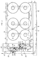
Figur 1- zwei hintereinander angeordnete Kettbaumgestelle mit je einem in Abzugsrichtung der Fäden endseitig angeordneten Nähstation und
Figur 2- eine Nähstation nach
Figur 1 in grösserem Massstab. Figur 3- eine genähte Fadenhalterung in perspektivischer Darstellung.
The method according to the invention is explained using an exemplary embodiment of a device which operates according to the method according to the invention. Such an exemplary embodiment is shown in the accompanying drawing and is explained on the basis of the following description. It shows:
- Figure 1
- two warp beam frames arranged one behind the other, each with a sewing station and arranged at the end in the direction of withdrawal of the threads
- Figure 2
- a sewing station according to Figure 1 on a larger scale.
- Figure 3
- a sewn thread holder in perspective.
Obwohl in der nachfolgenden Beschreibung eine Ausführungsvariante gemäss der Figur 1 beschrieben wird, bei der zwei Kettbaumgestelle vorhanden sind, ist dies für die Erfindung unwesentlich und lässt sich ohne weiteres auch realisieren bei einer Garnfärbeanlage, die lediglich mit einem Kettbaumgestell ausgerüstet ist. Ein Kettbaumgestell ist eine Stahlträgerkonstruktion, in der eine gerade Anzahl von auswechselbaren Kettbäumen drehbar gelagert sind. In der Zeichnung ist mit 1 ein erstes mit 2 ein zweites Kettbaumgestell bezeichnet. Zwischen den beiden Kettbaumgestellen 1 und 2 ist hier eine Vliesverbindungsstation 3 angeordnet, die jedoch nicht Gegenstand dieser Erfindung ist. Entlang der gesamten Garnfärbeanlage verlaufen Längsträger 4 auf beiden Seiten der Produktionlinie. Senkrecht zu den Längsträgern 4 sind Querträger 5 eingeschweisst. Auf diesen sind Schienen 6 angebracht, auf denen die Kettbaumgestelle 1 respektiv 2 senkrecht zur Verlaufsrichtung der Garnfärbenanlage aus der Produktionslinie heraus geschoben werden können. Entsprechend hat jedes Kettbaumgestell ein auf Rollen gelagertes Chassis 7. Auch auf dem Chassis 7 sind mehrere Trägerrahmen 8, im dargestellten Beispiel jeweils drei Trägerrahmen pro Kettbaumgestell, montiert. Auf jedem Trägerrahmen 8 lagern vier Kettbäume 9. Auf jedem Kettbaum sind beispielsweise rund vierhundert Fäden parallel aufgewickelt. Die im Kettbaumgestell unten gelagerten Kettbäume liefern die Fäden für ein unteres Vlies, die entsprechend oben gelagerten Ketttbäume die Fäden für ein oberes Vlies. Da die Umfangsgeschwindigkeit der Kettbäume 9 nur von der Abzugsgeschwindigkeit der Fäden abhängt, und alle Fäden gemeinsam abgezogen werden, ist auch die Umfangsgeschwindigkeit aller Kettbäume 9 gleich gross. Beim Einfädeln werden nun die vierhundert zu einem Knoten vereinten Kettfäden eines ersten Kettbaumes a hochgezogen und über den darüberliegenden Kettbaum b geleitet, wo sie mit den nächsten vierhundert vereinten Fäden des zweiten Kettbaumes b vereint werden. Diese achthundert Kettfäden werden nun über den nächsten Kettbaum c geführt und wiederum mit dessen vierhundert Fäden vereint, um schliesslich zum vierten Kettbaum d zu gelangen und dort wiederum mit dessen vierhundert Fäden vereint zu werden. Bei jeder Vereinigung wird somit das Vlies aus den parallel verlaufenden Fäden immer dichter gebildet. Die sechzehnhundert vereinten Fäden, die von einem ersten Trägerrahmen 8 kommen, werden nun über die Kettbäume des nächsten Trägerrahmens geführt bis schliesslich sämtliche Fäden über sämtliche Kettbäume 9 geführt sind und ein vereintes Vlies 10 bilden. Dieses vollständig vereinte Vlies 10 wird danach sogleich aufgeteilt in ein oberes Vlies 11 und ein unteres Vlies 12. Die beiden Teilvliese werden dann getrennt durch eine Nähstation 20 geführt. Hiernach werden das obere Vlies 11 und das untere Vlies 12 wieder zu einem vereinten Vlies 10 zusammengeführt und gelangt, in die hier nicht mehr zu beschreibende Vliesverbindungsstation 3, in den die beiden Teilvliese wieder aufgetrennt werden, um um das gesamte Kettbaumgestell geführt zu werden und schliesslich wieder vereint zum Färbebad B zu gelangen.Although an embodiment variant according to FIG. 1 is described in the following description, in which two warp beam frames are present, this is insignificant for the invention and can also be easily implemented in a yarn dyeing system which is only equipped with a warp beam frame. A warp beam frame is a steel support structure in which an even number of interchangeable warp beams are rotatably mounted. In the drawing, 1 denotes a first warp beam frame with 2 a second. Between the two
In der Figur 2 ist die Nähstation 20 in grösserem Massstab vereinfacht dargestellt. Die gesamte Nähstation 20 ruht zwischen zwei Seitenwangen 21, die an den Längsträgern 4 der Garnfärbeanlage angebracht sind. Ueber zwei untere Umlenkwalzen 22 wird das vereinte Vlies 10 zugeführt und in die beiden Teilvliese, nämlich dem oberen Vlies 11 und dem unteren Vlies 12 getrennt und getrennt je durch eine seperate Näheinheit 20′ respektiv 20˝ nach oben geführt. Ueber zwei oberen Umlenkwalzen 22 werden die beiden Teilvliese um 90° umgelenkt und wiederum zu einem vereinten Vlies 10 zusammengeführt. Die beiden Näheinheiten 20′ und 20˝ sind hier spiegelbildlich identisch übereinander versetzt ausgeführt. Jede Näheinheit 20′ beziehungsweise 20˝ besteht im wesentlichen aus einer Nähmaschine, deren Oberteil und Unterteil voneinander getrennt sind. Oberteil und Unterteil jeder Näheinheit ist separat auf einem Schlitten 28 montiert. Die Schlitten 28 sind auf Gleitstangen 25 gelagert und können mittels Gewindespindeln 23 synchron quer zur Verlaufsrichtung des entsprechenden Teilvlieses verschoben werden. Ueber parallel zu den Gewindespindeln 23 verlaufenden Antriebsspindeln 24, die beide ebenfalls synchron laufen, lassen sich Unterteil und Oberteil der Nähmaschine getrennt jedoch synchron treiben. Oberfaden und Unterfaden der Nähmaschine werden je von einer Fadenspule gespiesen, wobei jeweils die Oberfadenspule mit 26, die unterfadenspule mit 29 eingezeichnet ist. Ebenfalls auf jedem Schlitten 28 ist je eine Gurtbandspule 27 angeordnet. Jedes Teilvlies 11,12 wird so im Anfangsbereich und im Endbereich der Fäden zwischen zwei Gurtbändern eingenäht. Die beiden vernähten Gurtbänder bilden folglich eine Halterung aller parallelen Fäden eines oberen beziehungsweise unteren Vlieses. Diese Halterung formt somit einen Ersatz für die üblicherweise verwendeten metallenen Klemmkämme.
In der Figur 3 ist die Halterung im Detail dargestellt. Mit 30 sind die parallelen Fäden eines Ober- beziehungsweise Untervlieses bezeichnet. Quer zu ihrer Verlaufsrichtung kreuzen sie ein unteres Gurtband 31 und ein oberes Gurtband 32, beide Gurtbänder 31,32 sind mittels der Naht 33 miteinander verbunden. Auf der Seite hängen die freien Enden des Oberfadens 34 und Unterfaden 35 hinunter.
Während des Einziehens der Fäden befinden sich die beiden Näheinheiten 20′,20˝ vollständig auf der Seite einer der beiden Seitenwangen 21 und kommen somit nicht im Wege. Sind sämtliche Fäden, beziehungsweise das gesamte Vlies 10 durch das ganze Kettbaumgestell der Garnfärbeanlage eingezogen, so lassen sich entweder die Fäden des Obervlieses und Untervlieses nacheinander und getrennt mit einer Fadenhalterung aus den Gurtbändern 31 und 32 vernähen, oder auch beide Teilvliese zwar getrennt aber gleichzeitig mit den Gurtbändern vernähen. Dies ist einzig und allein davon abhängig, welche Distanz man zwischen den beiden Halterungen wünscht. Diese so erstellten, vollkommen flexiblen Garnhalterungen können vollständig durch die Garnfärbeanlage hindurch gefördert werden, ohne dass hierzu das Quetschwalzenwerk geöffnet werden müsste. Am Ende der Garnfärbelinie, kurz vor der Fadenaufwicklung kann man einfach an den freien Enden des oberen beziehungsweise unteren Nähfadens 34,35 ziehen und die Naht 33 geht auf. Die Bänder 31,32 lassen sich nun einfach wegziehen. Die Gurtbänder 31 und 32 können im Prinzip einfache Textilbänder sein. Es ist jedoch auch möglich, einseitig kunststoffbeschichtete Bänder zu verwenden, die eine höhere Verzugsfestigkeit haben. Die Wahl der Art der Gurtbänder wird vorwiegend durch die Art der zu färbenden Fäden 30 bestimmt.
Die hier nicht näher beschriebene Vliesverbindungsstation 3 zwischen dem ersten Kettbaumgestell 1 und dem zweiten Kettbaumgestell 2 dient dazu, die Enden der Fäden des einen Kettbaumgestelles mit dem Anfang der Fäden des anderen Kettbaumgestelles zu verbinden. Dies geschieht wiederum getrennt, einmal für das obere und das andere Mal für das untere Vlies. Der Vorteil einer derartigen Anordnung ist darin zu sehen, dass der Betrieb der Garnfärbeanlage ohne Stillstand beim Wechsel von einem Kettbaumgestell auf das andere Kettbaumgestell betrieben werden kann.In FIG. 2, the
The holder is shown in detail in FIG. With 30 the parallel threads of an upper or lower fleece are designated. They cross a lower webbing 31 and an upper webbing 32 transversely to their direction of travel, both webbings 31, 32 are connected to one another by means of the
While the threads are being drawn in, the two
The
Claims (9)
- Procedure for separately holding the leading and trailing end sections of the threads or an upper and a lower warp which are drawn from a warp beam and are passed through a yarn dyeing plant, characterised in that the threads of the upper and lower warps, after being drawn from the warp beam, are guided separately, in the direction in which they are drawn from the warp beam, through sewing units in a sewing mechanism, there being one sewing unit for each warp, in which units the warp thread ends are sewn together with two tape sections, one on each side of the warp, the tape sections being guided transversely to the direction of travel of the threads, before the two warp strands are brought together and drawn through a further yarn dyeing plant, and in that the two previously separate thread warps are passed through an active press-roller mechanism in the yarn dyeing plant after being combined into a single warp.
- Procedure according to Claim 1, characterised in that the two separate warps in the sewing mechanism are sewn simultaneously to the tapes on each side of the warp.
- Procedure according to Claim 1, characterised in that the two separate warps in the sewing mechanism are sewn non-simultaneously to the tapes, both warps being pulled further after the first seam, to that the tapes on the other warp are spatially displaced in relation to those sewn first.
- Procedure according to Claim 1, characterised in that webbing material is used for the tapes.
- Procedure according to Claim 1, characterised in that webbing material coated on one side is used for the tapes.
- Procedure according to Claim 1, characterised in that the upper and lower thread ends of the single seam holding together the tapes of a warp hang down freely on each side of the warp, so that after the warp has passed through the dyeing plant the threads can be grasped and the seam unravelled, the tapes being then removed before the combined warp is rolled up.
- Device for carrying out the procedure according to at least one of Claims 1-6, characterised in that a side-bearer (21) of a sewing mechanism (20) is mounted to each of the longitudinal beams (4) of a yarn dyeing plant, in the direction in which the threads are drawn from the warp beam (1,2), between which side-bearers two independent sewing units (20',20'') are guided on slide rods, are displaceable by threaded spindles and are driven by drive spindles, the upper thread-sewing section and the lower thread-sewing section of each sewing unit being spatially entirely separate, but synchronously movable, each being mounted on a sliding carriage.
- Device according to Claim 7, characterised in that each upper thread-sewing section and each lower thread-sewing section of each sewing unit (20',20'') has associated with it a thread spool and a webbing tape spool.
- Device according to Claim 7, characterised in that each sewing unit has an associated drive motor, which motor synchronously drives both threaded spindles (23) and both drive spindles (24) of both sewing sections of a sewing unit by means of disc wheels, the disc wheels of the drive spindles (24) being capable of being engaged and disengaged.
Applications Claiming Priority (2)
| Application Number | Priority Date | Filing Date | Title |
|---|---|---|---|
| CH190691 | 1991-06-27 | ||
| CH1906/91 | 1991-06-27 |
Publications (2)
| Publication Number | Publication Date |
|---|---|
| EP0520947A1 EP0520947A1 (en) | 1992-12-30 |
| EP0520947B1 true EP0520947B1 (en) | 1995-08-30 |
Family
ID=4221363
Family Applications (1)
| Application Number | Title | Priority Date | Filing Date |
|---|---|---|---|
| EP19920810474 Expired - Lifetime EP0520947B1 (en) | 1991-06-27 | 1992-06-22 | Method and device to maintain groups of warp yarns separate while passing through a dyeing apparatus. |
Country Status (3)
| Country | Link |
|---|---|
| EP (1) | EP0520947B1 (en) |
| DE (1) | DE59203439D1 (en) |
| ES (1) | ES2076731T3 (en) |
Families Citing this family (1)
| Publication number | Priority date | Publication date | Assignee | Title |
|---|---|---|---|---|
| ES2131182T3 (en) * | 1993-12-22 | 1999-07-16 | Benninger Ag Maschf | PROCEDURE AND DEVICE FOR WINDING BANDS FOR BURNING. |
Family Cites Families (3)
| Publication number | Priority date | Publication date | Assignee | Title |
|---|---|---|---|---|
| US3234061A (en) * | 1963-01-24 | 1966-02-08 | Deering Milliken Res Corp | Method of sewing textile webs together |
| DE3261173D1 (en) * | 1981-04-16 | 1984-12-13 | Quikoton Ag | Join between the ends of textile materials |
| US4815405A (en) * | 1987-10-13 | 1989-03-28 | Young Engineering, Inc, | Apparatus for splicing indeterminate lengths of fabric |
-
1992
- 1992-06-22 DE DE59203439T patent/DE59203439D1/en not_active Expired - Fee Related
- 1992-06-22 ES ES92810474T patent/ES2076731T3/en not_active Expired - Lifetime
- 1992-06-22 EP EP19920810474 patent/EP0520947B1/en not_active Expired - Lifetime
Also Published As
| Publication number | Publication date |
|---|---|
| EP0520947A1 (en) | 1992-12-30 |
| ES2076731T3 (en) | 1995-11-01 |
| DE59203439D1 (en) | 1995-10-05 |
Similar Documents
| Publication | Publication Date | Title |
|---|---|---|
| DE3834689C2 (en) | ||
| DE2731564A1 (en) | DEVICE FOR UNWINDING A THREAD BUNCH FROM A THREAD SUPPLY DEVICE AND FORWARDING THE THREAD BUNCH INTO A YARN PROCESSING MACHINE | |
| DE2613798A1 (en) | PROCESS FOR SIZING AND DRYING CHAIN FEEDS AND DEVICE FOR CARRYING OUT THE PROCESS | |
| DE3108944C2 (en) | Method and device for the production of two-dimensional textile goods having warp threads | |
| DE2350558B2 (en) | PULL TEXTURING MACHINE | |
| DE2159860B2 (en) | SYSTEM FOR REPLACING EMPTY FOR FULL SUPPLY REELS ON STRETCH TWISTING MACHINES OR STRETCH WINDING MACHINES | |
| DE2940867C2 (en) | Chainless mercerising system for wide-spread textile goods in web or tube form | |
| DE3429153C2 (en) | Creel | |
| EP0520947B1 (en) | Method and device to maintain groups of warp yarns separate while passing through a dyeing apparatus. | |
| CH633836A5 (en) | METHOD AND DEVICE FOR TORNING A TWO OR MULTIPLE YARN IN THREAD BREAKINGS. | |
| EP0284945B1 (en) | Air jet texturing apparatus | |
| CH626926A5 (en) | ||
| EP0590120B1 (en) | Process and device for facilitating warp changing | |
| DE2541572C3 (en) | Device for winding a roving or sliver into a bobbin on a bobbin tube | |
| DE1916474A1 (en) | Process for treating fiber material | |
| DE1560263C3 (en) | Two-for-one twisting machine | |
| DE861737C (en) | Method and device for twisting the individual threads of a running thread bundle one after the other on the spindles of a ring twister | |
| DE1940525A1 (en) | Method and device for drawing in threads in draw-twisting or draw-winding machines | |
| DE705687C (en) | Process for the continuous passage of strong, endless synthetic fiber bands through several successive bath fluids | |
| DE557102C (en) | Wet treatment of individual fibers in the form of roving or finished yarn and a device for this | |
| DE1760456C3 (en) | Device for exchanging delivery spools on a two-for-one twisting machine | |
| DE2530508C3 (en) | Process for the continuous manufacture of a package | |
| DE2951695C2 (en) | ||
| DE2427965A1 (en) | PULL TEXTURING MACHINE | |
| DE2725348A1 (en) | Plastic tape processing machine - with cutter bar and hot stretch rolls in common roll stand |
Legal Events
| Date | Code | Title | Description |
|---|---|---|---|
| PUAI | Public reference made under article 153(3) epc to a published international application that has entered the european phase |
Free format text: ORIGINAL CODE: 0009012 |
|
| AK | Designated contracting states |
Kind code of ref document: A1 Designated state(s): BE CH DE ES IT LI |
|
| 17P | Request for examination filed |
Effective date: 19930603 |
|
| 17Q | First examination report despatched |
Effective date: 19941110 |
|
| RHK1 | Main classification (correction) |
Ipc: D03J 1/18 |
|
| GRAA | (expected) grant |
Free format text: ORIGINAL CODE: 0009210 |
|
| AK | Designated contracting states |
Kind code of ref document: B1 Designated state(s): BE CH DE ES IT LI |
|
| PG25 | Lapsed in a contracting state [announced via postgrant information from national office to epo] |
Ref country code: BE Effective date: 19950830 |
|
| REF | Corresponds to: |
Ref document number: 59203439 Country of ref document: DE Date of ref document: 19951005 |
|
| REG | Reference to a national code |
Ref country code: ES Ref legal event code: FG2A Ref document number: 2076731 Country of ref document: ES Kind code of ref document: T3 |
|
| ITF | It: translation for a ep patent filed |
Owner name: ORGANIZZAZIONE D'AGOSTINI |
|
| PLBE | No opposition filed within time limit |
Free format text: ORIGINAL CODE: 0009261 |
|
| STAA | Information on the status of an ep patent application or granted ep patent |
Free format text: STATUS: NO OPPOSITION FILED WITHIN TIME LIMIT |
|
| 26N | No opposition filed | ||
| REG | Reference to a national code |
Ref country code: CH Ref legal event code: PUE Owner name: GOTTLIEB BENZ TRANSFER- BENNINGER ZELL GMBH |
|
| REG | Reference to a national code |
Ref country code: ES Ref legal event code: PC2A |
|
| REG | Reference to a national code |
Ref country code: CH Ref legal event code: NV Representative=s name: HEPP, WENGER & RYFFEL AG |
|
| PGFP | Annual fee paid to national office [announced via postgrant information from national office to epo] |
Ref country code: CH Payment date: 20040831 Year of fee payment: 13 |
|
| PG25 | Lapsed in a contracting state [announced via postgrant information from national office to epo] |
Ref country code: LI Free format text: LAPSE BECAUSE OF NON-PAYMENT OF DUE FEES Effective date: 20050630 Ref country code: CH Free format text: LAPSE BECAUSE OF NON-PAYMENT OF DUE FEES Effective date: 20050630 |
|
| REG | Reference to a national code |
Ref country code: CH Ref legal event code: PL |
|
| PGFP | Annual fee paid to national office [announced via postgrant information from national office to epo] |
Ref country code: ES Payment date: 20080605 Year of fee payment: 17 |
|
| PGFP | Annual fee paid to national office [announced via postgrant information from national office to epo] |
Ref country code: BE Payment date: 20080606 Year of fee payment: 17 Ref country code: IT Payment date: 20080530 Year of fee payment: 17 |
|
| PGFP | Annual fee paid to national office [announced via postgrant information from national office to epo] |
Ref country code: DE Payment date: 20080523 Year of fee payment: 17 |
|
| PG25 | Lapsed in a contracting state [announced via postgrant information from national office to epo] |
Ref country code: DE Free format text: LAPSE BECAUSE OF NON-PAYMENT OF DUE FEES Effective date: 20100101 |
|
| REG | Reference to a national code |
Ref country code: ES Ref legal event code: FD2A Effective date: 20090623 |
|
| PG25 | Lapsed in a contracting state [announced via postgrant information from national office to epo] |
Ref country code: ES Free format text: LAPSE BECAUSE OF NON-PAYMENT OF DUE FEES Effective date: 20090623 |
|
| PG25 | Lapsed in a contracting state [announced via postgrant information from national office to epo] |
Ref country code: IT Free format text: LAPSE BECAUSE OF NON-PAYMENT OF DUE FEES Effective date: 20090622 |