EP0520719B1 - Ausgleichgewichtsbefestigungstechnik - Google Patents
Ausgleichgewichtsbefestigungstechnik Download PDFInfo
- Publication number
- EP0520719B1 EP0520719B1 EP92305694A EP92305694A EP0520719B1 EP 0520719 B1 EP0520719 B1 EP 0520719B1 EP 92305694 A EP92305694 A EP 92305694A EP 92305694 A EP92305694 A EP 92305694A EP 0520719 B1 EP0520719 B1 EP 0520719B1
- Authority
- EP
- European Patent Office
- Prior art keywords
- aluminum
- drive shaft
- steel
- transition material
- counterweight
- Prior art date
- Legal status (The legal status is an assumption and is not a legal conclusion. Google has not performed a legal analysis and makes no representation as to the accuracy of the status listed.)
- Expired - Lifetime
Links
- 238000000034 method Methods 0.000 title claims description 44
- 229910052782 aluminium Inorganic materials 0.000 claims description 81
- XAGFODPZIPBFFR-UHFFFAOYSA-N aluminium Chemical compound [Al] XAGFODPZIPBFFR-UHFFFAOYSA-N 0.000 claims description 81
- 229910000831 Steel Inorganic materials 0.000 claims description 80
- 239000010959 steel Substances 0.000 claims description 80
- 239000000463 material Substances 0.000 claims description 62
- 230000007704 transition Effects 0.000 claims description 54
- 238000003466 welding Methods 0.000 claims description 36
- 230000008569 process Effects 0.000 claims description 28
- 239000002131 composite material Substances 0.000 claims description 11
- 239000004411 aluminium Substances 0.000 claims 1
- 230000008901 benefit Effects 0.000 description 4
- 230000007797 corrosion Effects 0.000 description 3
- 238000005260 corrosion Methods 0.000 description 3
- 230000004927 fusion Effects 0.000 description 3
- 239000012141 concentrate Substances 0.000 description 2
- 230000020169 heat generation Effects 0.000 description 2
- 229910000765 intermetallic Inorganic materials 0.000 description 2
- 238000002844 melting Methods 0.000 description 2
- 230000008018 melting Effects 0.000 description 2
- 229910001209 Low-carbon steel Inorganic materials 0.000 description 1
- 239000000853 adhesive Substances 0.000 description 1
- 230000001070 adhesive effect Effects 0.000 description 1
- AZDRQVAHHNSJOQ-UHFFFAOYSA-N alumane Chemical group [AlH3] AZDRQVAHHNSJOQ-UHFFFAOYSA-N 0.000 description 1
- 230000015572 biosynthetic process Effects 0.000 description 1
- 230000008602 contraction Effects 0.000 description 1
- 230000007547 defect Effects 0.000 description 1
- 238000009792 diffusion process Methods 0.000 description 1
- 230000000694 effects Effects 0.000 description 1
- 229910052751 metal Inorganic materials 0.000 description 1
- 239000002184 metal Substances 0.000 description 1
- 150000002739 metals Chemical class 0.000 description 1
- 230000004048 modification Effects 0.000 description 1
- 238000012986 modification Methods 0.000 description 1
- 230000009467 reduction Effects 0.000 description 1
- 239000013585 weight reducing agent Substances 0.000 description 1
Images
Classifications
-
- F—MECHANICAL ENGINEERING; LIGHTING; HEATING; WEAPONS; BLASTING
- F16—ENGINEERING ELEMENTS AND UNITS; GENERAL MEASURES FOR PRODUCING AND MAINTAINING EFFECTIVE FUNCTIONING OF MACHINES OR INSTALLATIONS; THERMAL INSULATION IN GENERAL
- F16F—SPRINGS; SHOCK-ABSORBERS; MEANS FOR DAMPING VIBRATION
- F16F15/00—Suppression of vibrations in systems; Means or arrangements for avoiding or reducing out-of-balance forces, e.g. due to motion
- F16F15/32—Correcting- or balancing-weights or equivalent means for balancing rotating bodies, e.g. vehicle wheels
-
- F—MECHANICAL ENGINEERING; LIGHTING; HEATING; WEAPONS; BLASTING
- F16—ENGINEERING ELEMENTS AND UNITS; GENERAL MEASURES FOR PRODUCING AND MAINTAINING EFFECTIVE FUNCTIONING OF MACHINES OR INSTALLATIONS; THERMAL INSULATION IN GENERAL
- F16D—COUPLINGS FOR TRANSMITTING ROTATION; CLUTCHES; BRAKES
- F16D1/00—Couplings for rigidly connecting two coaxial shafts or other movable machine elements
- F16D1/06—Couplings for rigidly connecting two coaxial shafts or other movable machine elements for attachment of a member on a shaft or on a shaft-end
- F16D1/064—Couplings for rigidly connecting two coaxial shafts or other movable machine elements for attachment of a member on a shaft or on a shaft-end non-disconnectable
- F16D1/068—Couplings for rigidly connecting two coaxial shafts or other movable machine elements for attachment of a member on a shaft or on a shaft-end non-disconnectable involving gluing, welding or the like
-
- B—PERFORMING OPERATIONS; TRANSPORTING
- B23—MACHINE TOOLS; METAL-WORKING NOT OTHERWISE PROVIDED FOR
- B23K—SOLDERING OR UNSOLDERING; WELDING; CLADDING OR PLATING BY SOLDERING OR WELDING; CUTTING BY APPLYING HEAT LOCALLY, e.g. FLAME CUTTING; WORKING BY LASER BEAM
- B23K11/00—Resistance welding; Severing by resistance heating
- B23K11/002—Resistance welding; Severing by resistance heating specially adapted for particular articles or work
-
- F—MECHANICAL ENGINEERING; LIGHTING; HEATING; WEAPONS; BLASTING
- F16—ENGINEERING ELEMENTS AND UNITS; GENERAL MEASURES FOR PRODUCING AND MAINTAINING EFFECTIVE FUNCTIONING OF MACHINES OR INSTALLATIONS; THERMAL INSULATION IN GENERAL
- F16F—SPRINGS; SHOCK-ABSORBERS; MEANS FOR DAMPING VIBRATION
- F16F15/00—Suppression of vibrations in systems; Means or arrangements for avoiding or reducing out-of-balance forces, e.g. due to motion
- F16F15/32—Correcting- or balancing-weights or equivalent means for balancing rotating bodies, e.g. vehicle wheels
- F16F15/322—Correcting- or balancing-weights or equivalent means for balancing rotating bodies, e.g. vehicle wheels the rotating body being a shaft
-
- B—PERFORMING OPERATIONS; TRANSPORTING
- B23—MACHINE TOOLS; METAL-WORKING NOT OTHERWISE PROVIDED FOR
- B23K—SOLDERING OR UNSOLDERING; WELDING; CLADDING OR PLATING BY SOLDERING OR WELDING; CUTTING BY APPLYING HEAT LOCALLY, e.g. FLAME CUTTING; WORKING BY LASER BEAM
- B23K2103/00—Materials to be soldered, welded or cut
- B23K2103/02—Iron or ferrous alloys
- B23K2103/04—Steel or steel alloys
-
- B—PERFORMING OPERATIONS; TRANSPORTING
- B23—MACHINE TOOLS; METAL-WORKING NOT OTHERWISE PROVIDED FOR
- B23K—SOLDERING OR UNSOLDERING; WELDING; CLADDING OR PLATING BY SOLDERING OR WELDING; CUTTING BY APPLYING HEAT LOCALLY, e.g. FLAME CUTTING; WORKING BY LASER BEAM
- B23K2103/00—Materials to be soldered, welded or cut
- B23K2103/08—Non-ferrous metals or alloys
- B23K2103/10—Aluminium or alloys thereof
Definitions
- the present invention relates to use of transition materials and, more particularly, to an apparatus and method for balancing an aluminum drive shaft for rotation about an axis using transition materials.
- drive shafts for vehicles may be developed of aluminum, which offers substantial weight reduction and reduced rotational inertia over steel drive shafts.
- counterweights must be attachable to the shafts in order to properly balance the shafts.
- the preferred material for these counterweights is steel, since steel has a significantly greater mass density than aluminum and a much larger piece of aluminum would be required to perform as a counterweight if aluminum were used.
- joining these two materials presents many problems.
- One method of joining aluminum and steel is resistance projection welding.
- the typical resistance projection welding method of joining aluminum to steel is generally considered unfeasible due to formation of undesirable discontinuities or defects along the bond line or weld zone.
- Another method of joining aluminum to steel is fusion welding.
- steel and aluminum are of considerably different melting points, making fusion welding difficult.
- steel and aluminum form a series of brittle intermetallics.
- problems occur in trying to fusion weld steel aluminum including discontinuities in the weld line, weak welds between two incompatible materials such as steel and aluminum, breakage due to differential expansion and contraction, diffusion forming brittle intermetallic compounds at the interface between the two materials, high stresses due to residual strains from the welding operation, and galvanic couples that cause corrosion.
- GB-A-2147388 discloses a method of securing a balance weight to a drive shaft.
- the generally cylindrical balance weight is formed with a curved end surface which conforms to the outer surface of the drive shaft and has a coaxial aperture formed through it.
- the balance weight and drive shaft are typically formed of dissimilar metals, such as steel and aluminum. While the balance weight is maintained against the drive shaft at a predetermined location satisfactory for balancing the drive shaft, adhesive material, such as molten aluminum wire, is supplied within the aperture so as form a spot or rivet type weld.
- a metallic composite adapted for attachment to an aluminum drive shaft for imparting mechanical balance to said aluminum drive shaft during rotation thereof, the composite comprising a steel counterweight and a transition material for disposition between the aluminum drive shaft and the counterweight, wherein the transition material comprises a laminate structure having a first, aluminum surface to be placed against the aluminum drive shaft, and a second, steel surface to be placed against the steel counterweight, and in which there are provided one or more intermediate laminate regions between the aluminum surface and the steel surface.
- the transition material is projection welded, which allows for the metering of heat flow from the steel to the aluminum.
- An advantage of the use of a transition material during the resistance welding process is the reduction of the amount of heat introduced to the aluminum drive shaft, which reduces the thermal expansion and deformation of the drive shaft during the counterweight attachment.
- the resistance welding process provides the further advantage of eliminating expulsion from the aluminum and minimizing expulsion from the steel during the welding process.
- transition material to attach the steel counterweights to the aluminum drive shaft provides the advantage of reducing the possibility of galvanic corrosion at the aluminum-steel interface.
- an aluminum-aluminum bond is created between the aluminum drive shaft and the first surface of the transition material from heat lost in the steel during the resistance welding process.
- a steel-steel bond is created between the steel counterweight and the second surface of the transition material from heat generated in the steel counterweight during the resistance welding process.
- the apparatus may further comprise a plurality of outwardly projecting geometric shapes on the second surface of the transition material to prevent excess heat from being transmitted to the aluminum during the resistance welding process.
- a method of balancing an aluminum drive shaft comprising the steps of:
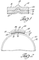
- the transition material has a first surface 12 and a second surface 14.
- Surface 12 is aluminum and surface 14 is steel.
- the transition material 10 is also comprised of at least two, and preferably four, layers 16, 18, 20, and 22.
- Layers 16, 18, and 20 are aluminum layers of varying grades.
- layers 16 and 20 comprise aluminum 1145
- layer 18 comprises aluminum 5052.
- the fourth layer 22 is a steel layer, preferably low carbon steel such as steel 1008.
- using the transition material 10 permits the attachment of one or more steel counterweights 28 to an aluminum drive shaft 30 by means of a resistance welding process, without encountering the problems faced during resistance welding of steel directly to aluminum. Additionally, the resistance welding process using the transition material 10 eliminates expulsion from the aluminum and minimizes expulsion from the steel.
- the resistance welding process which may be performed by any suitable means including a resistance spot welding machine, is applied to the aluminum drive shaft 30, the steel counterweight 28, and the transition material 10 to create a flow of heat from the steel counterweight 28 to the aluminum tube drive shaft 30. This flow of heat can be metered to regulate the amount of heat generated in the steel counterweight 28 during the resistance welding process.
- the preferred thickness of the transition material 10 is approximately 0.050 inches, in order to achieve exceptionally good weldability and weld integrity.
- one or more geometric shapes 24, such as hemispheres, dimples, or annular rings, may be formed, projecting outwardly, on the transition material 10.
- the geometric shape 24 projects outwardly on the steel surface 14 of the transition material 10, as illustrated in Figure 1.
- the geometric shape 24 concentrates the heat generation in the steel counterweight 28 at the steel surface 14 and improves the heat balance during the resistance welding process, preventing excess heat from being transmitted to the aluminum drive shaft 30.
- the geometric shape 24 may be any of a variety of shapes, depending on the weight and size of the steel counterweight 28 to be attached to the aluminum drive shaft 30.
- Figure 2 is an exploded view of the layers which form the transition material 10.
- the transition material 10 is positioned such that the surface 12 will contact an outer surface 32 of the aluminum drive shaft 30, in order to create an aluminum-aluminum bond between the aluminum drive shaft 30 and the first surface 12 of the transition material 10, from heat lost during the resistance welding process.
- the surface 14 will contact an inner surface 34 of the steel counterweight 28 in order to create a steel-steel bond between the steel counterweight 28 and the second surface 14 of the transition material 10, from heat generated in the steel counterweight 28 during the resistance welding process.
- the geometric shape 24 projects outwardly from surface 14 of transition material 10, toward the steel counterweight 28, to concentrate heat generation in the steel counterweight 28 at the steel-steel interface during the resistance welding process.
- an aluminum to steel transition material 10 is used to attach steel counterweights 28 to aluminum drive shafts 30 through resistance projection welding.
- the transition material 10 is disposed between the outer surface 32 of the aluminum drive shaft 30 and the inner surface 34 of the steel counterweight 28.
- the surface 12 of the transition material 10 adjacent to the drive shaft 30 is aluminum, and the counterweight 28 is steel.
- the transition material may comprise other combinations of materials.
- the counterweight 28, the transition material 10, and the drive shaft 30 are subjected to a resistance welding process. During such welding, heat generated in the steel counterweight 28 forms a steel-steel bond between the counterweight 28 and the surface 14 of the transition material 10. Heat lost from this weld is conducted into the aluminum, forming an aluminum-aluminum bond between the drive shaft 30 and the surface 12 of the transition material 10 adjacent to the drive shaft 30.
- the plurality of geometric shapes 24 may be formed on the surface 14 of the transition material 10 adjacent to the counterweight, to localize the application of heat to the transition material 10 and prevent excess heat from being transmitted to the aluminum drive shaft 30, so as to prevent undesirable melting.
Landscapes
- Engineering & Computer Science (AREA)
- General Engineering & Computer Science (AREA)
- Mechanical Engineering (AREA)
- Physics & Mathematics (AREA)
- Acoustics & Sound (AREA)
- Aviation & Aerospace Engineering (AREA)
- Shafts, Cranks, Connecting Bars, And Related Bearings (AREA)
- Structures Of Non-Positive Displacement Pumps (AREA)
Claims (15)
- Metallisches Verbundmaterial zur Befestigung an einer Aluminiumantriebswelle (32), um diese während ihrer Rotation mechanisch auszuwuchten, wobei das Verbundmaterial ein Stahlgegengewicht (28) und ein Übergangsmaterial (10) aufweist zur Anordnung zwischen der Aluminiumantriebswelle (32) und dem Gegengewicht (28), dadurch gekennzeichnet, daß das Übergangsmaterial (10) eine Laminat-Struktur hat mit einer ersten Aluminiumoberfläche (12) zur Anordnung gegen die Aluminiumantriebswelle (32), und einer zweiten Stahloberfläche (14) zur Anordnung gegen das Stahlgegengewicht (28), und daß eine oder mehr Laminat-Zwischenbereiche (20, 18) vorgesehen sind zwischen der Aluminiumoberfläche (12) und der Stahloberfläche (14).
- Metallisches Verbundmaterial nach Anspruch 1, gekennzeichnet durch Einrichtungen zur Schaffung einer Aluminium-Aluminium-Bindung zwischen der Aluminiumantriebswelle (32) und der ersten Oberfläche (12) des Übergangsmateriales (10) aus dem Wärmeverlust während eines Widerstands-Schweißprozesses;
sowie durch Einrichtungen zum Schaffen einer Stahl-Stahl-Bindung zwischen dem Stahlgegengewicht (28) und der zweiten Oberfläche (14) des Übergangsmateriales (10) aus der Wärme, die im Stahlgegengewicht (28) während des Widerstands-Schweißprozesses erzeugt wird. - Metallisches Verbundmaterial nach Anspruch 1 oder 2, gekennzeichnet durch eine Mehrzahl von nach außen vorstehenden geometrischen Formen an der zweiten Oberfläche (14) des Übergangsmateriales (10), um zu verhindern, daß übermäßige Wärme auf die Aluminiumantriebswelle (32) übertragen wird.
- Metallisches Verbundmaterial nach Anspruch 2 oder Anspruch 3, dadurch gekennzeichnet, daß durch den Widerstands-Schweißprozeß ein Wärmefluß erzeugt wird.
- Metallisches Verbundmaterial nach Anspruch 4, gekennzeichnet durch Einrichtungen zum Bemessen des Wärmeflusses vom Stahlgegengewicht (28) zur Aluminiumantriebswelle (32).
- Metallisches Verbundmaterial nach einem der vorhergehenden Ansprüche, soweit diese auf Anspruch 2 bezogen sind, dadurch gekennzeichnet, daß der Widerstands-Schweißprozeß Mittel umfaßt, um einen Ausstoß aus der Aluminiumantriebswelle (32) und der ersten Oberfläche (12) des Übergangsmateriales (10) zu eliminieren.
- Metallisches Verbundmaterial nach einem der vorhergehenden Ansprüche, soweit diese auf Anspruch 2 bezogen sind, dadurch gekennzeichnet, daß der Widerstands-Schweißprozeß Mittel umfaßt, um einen Ausstoß aus dem Stahlgegengewicht (28) und der zweiten Oberfläche des Übergangsmateriales zu minimieren.
- Verfahren zum Ausgleichen einer Aluminiumantriebswelle (32), welche eine äußere Oberfläche hat, die radial weg von einer Achse gerichtet ist, um welche die Aluminiumantriebswelle rotiert, wobei ein Stahlgegengewicht (28) bereitgestellt wird, ein Übergangsmaterial (10) zwischen der äußeren Oberfläche der Aluminiumantriebswelle (32) und einer inneren Oberfläche des Stahlgegengewichtes (28) angeordnet wird sowie ein Widerstands-Schweißprozeß auf die Aluminiumantriebswelle (32), das Stahlgegengewicht (28) und das Übergangsmaterial (10) angewandt wird, um die innere Oberfläche des Stahlgegengewichtes (28) mit der äußeren Oberfläche der Aluminiumantriebswelle (32) zu verschweißen, dadurch gekennzeichnet, daß das Übergangsmaterial eine erste Oberfläche (12) angrenzend an die Aluminiumantriebswelle (32) sowie eine zweite Oberfläche (14) angrenzend an das Stahlgegengewicht (28) aufweist, und daß die erste Oberfläche Aluminium und die zweite Oberfläche Stahl ist.
- Verfahren nach Anspruch 8, dadurch gekennzeichnet, daß eine Aluminium-Aluminium-Bindung zwischen der Aluminiumantriebswelle (32) und der ersten Oberfläche (12) des Übergangsmateriales (10) geschaffen wird aus dem Wärmeverlust während der Ausführung des Widerstands-Schweißprozesses, daß ferner eine Stahl-Stahl-Bindung zwischen dem Stahlgegengewicht und der zweiten Oberfläche (14) des Übergangsmateriales (10) geschaffen wird aus der Wärme, welche im Stahlgegengewicht (28) während der Ausführung des Widerstands-Schweißprozesses erzeugt wird.
- Verfahren nach Anspruch 8 oder 9, dadurch gekennzeichnet, daß eine Mehrzahl von nach außen vorragenden geometrischen Formen (24) an der zweiten Oberfläche (14) des Übergangsmateriales (10) geschaffen wird, um zu verhindern, daß übermäßige Wärme auf die Aluminiumantriebswelle (32) übertragen wird.
- Verfahren nach einem der Ansprüche 8 - 10, dadurch gekennzeichnet, daß durch den Widerstands-Schweißprozeß ein Wärmefluß erzeugt wird.
- Verfahren nach Anspruch 11, dadurch gekennzeichnet, daß der Wärmefluß vom Stahlgegengewicht (28) zur Aluminiumantriebswelle (32) bemessen wird.
- Verfahren nach einem der Ansprüche 8 - 12, dadurch gekennzeichnet, daß bei der Ausführung des Widerstands-Schweißprozesses ein Ausstoß aus der Aluminiumantriebswelle (32) und der ersten Oberfläche (12) des Übergangsmateriales (10) eliminiert wird.
- Verfahren nach einem der Ansprüche 8 - 13, dadurch gekennzeichnet, daß beim Ausführen des Widerstands-Schweißprozesses ein Austreiben aus dem Stahlgegengewicht (28) und der zweiten Oberfläche (14) des Übergangsmateriales (10) minimiert wird.
- Aluminiumantriebswelle (32), gekennzeichnet durch ein metallisches Verbundmaterial (10, 28) nach einem der Ansprüche 1 - 7.
Applications Claiming Priority (2)
| Application Number | Priority Date | Filing Date | Title |
|---|---|---|---|
| US720225 | 1985-04-05 | ||
| US72022591A | 1991-06-25 | 1991-06-25 |
Publications (2)
| Publication Number | Publication Date |
|---|---|
| EP0520719A1 EP0520719A1 (de) | 1992-12-30 |
| EP0520719B1 true EP0520719B1 (de) | 1996-05-29 |
Family
ID=24893164
Family Applications (1)
| Application Number | Title | Priority Date | Filing Date |
|---|---|---|---|
| EP92305694A Expired - Lifetime EP0520719B1 (de) | 1991-06-25 | 1992-06-22 | Ausgleichgewichtsbefestigungstechnik |
Country Status (8)
| Country | Link |
|---|---|
| EP (1) | EP0520719B1 (de) |
| JP (1) | JPH05263875A (de) |
| KR (1) | KR100268761B1 (de) |
| BR (1) | BR9202370A (de) |
| CA (1) | CA2069386A1 (de) |
| DE (1) | DE69211060T2 (de) |
| MX (1) | MX9203330A (de) |
| TW (1) | TW219917B (de) |
Cited By (10)
| Publication number | Priority date | Publication date | Assignee | Title |
|---|---|---|---|---|
| US6870124B2 (en) | 2002-05-08 | 2005-03-22 | Dana Corporation | Plasma-assisted joining |
| US7189940B2 (en) | 2002-12-04 | 2007-03-13 | Btu International Inc. | Plasma-assisted melting |
| US7432470B2 (en) | 2002-05-08 | 2008-10-07 | Btu International, Inc. | Surface cleaning and sterilization |
| US7445817B2 (en) | 2002-05-08 | 2008-11-04 | Btu International Inc. | Plasma-assisted formation of carbon structures |
| US7465362B2 (en) | 2002-05-08 | 2008-12-16 | Btu International, Inc. | Plasma-assisted nitrogen surface-treatment |
| US7494904B2 (en) | 2002-05-08 | 2009-02-24 | Btu International, Inc. | Plasma-assisted doping |
| US7498066B2 (en) | 2002-05-08 | 2009-03-03 | Btu International Inc. | Plasma-assisted enhanced coating |
| US7497922B2 (en) | 2002-05-08 | 2009-03-03 | Btu International, Inc. | Plasma-assisted gas production |
| US7560657B2 (en) | 2002-05-08 | 2009-07-14 | Btu International Inc. | Plasma-assisted processing in a manufacturing line |
| US7638727B2 (en) | 2002-05-08 | 2009-12-29 | Btu International Inc. | Plasma-assisted heat treatment |
Families Citing this family (8)
| Publication number | Priority date | Publication date | Assignee | Title |
|---|---|---|---|---|
| US5633093A (en) * | 1991-06-25 | 1997-05-27 | Dana Corporation | Counterweight attachment technique |
| AU669931B2 (en) * | 1992-10-28 | 1996-06-27 | Unidrive Pty. Ltd. | Propeller shaft |
| GB2272041B (en) * | 1992-10-28 | 1995-10-25 | Unidrive Pty Ltd | Propeller shafts |
| AU685475B2 (en) * | 1993-08-25 | 1998-01-22 | Dana Automotive Systems Group, Llc | Counterweight attachment technique |
| DE69419501T2 (de) * | 1993-11-15 | 1999-11-18 | Nippon Steel Corp., Tokio/Tokyo | Widerstandsschweissverfahren für stahl- und aluminium-metallplatten und widerstandsschweissmaterial |
| US5783794A (en) * | 1993-11-15 | 1998-07-21 | Nippon Steel Corporation | Method and material for resistance welding steel-base metal sheet to aluminum-base metal sheet |
| EP0771966A3 (de) * | 1995-10-19 | 1998-09-16 | American Axle & Manufacturing Inc. | Dynamisch ausgewuchtete Antriebswelle und deren Auswuchtverfahren |
| US11300153B2 (en) * | 2019-03-09 | 2022-04-12 | GM Global Technology Operations LLC | Component having metallic transition material on base and method of forming |
Family Cites Families (4)
| Publication number | Priority date | Publication date | Assignee | Title |
|---|---|---|---|---|
| DE3140368A1 (de) * | 1981-10-10 | 1983-01-05 | Daimler-Benz Ag, 7000 Stuttgart | "gelenkwelle" |
| ATE18729T1 (de) * | 1981-12-15 | 1986-04-15 | Alusuisse | Verfahren zur herstellung einer schweissverbindung sowie zwischenteil zu dessen durchfuehrung. |
| DE3303237C2 (de) * | 1982-10-07 | 1985-11-28 | Schäfer Werke GmbH, 5908 Neunkirchen | Wärmetauscher, insbesondere Heizkörper |
| GB2147388B (en) * | 1983-09-29 | 1986-10-08 | Dana Corp | Balance weights |
-
1992
- 1992-05-22 CA CA002069386A patent/CA2069386A1/en not_active Abandoned
- 1992-05-26 TW TW081104113A patent/TW219917B/zh active
- 1992-06-22 EP EP92305694A patent/EP0520719B1/de not_active Expired - Lifetime
- 1992-06-22 DE DE69211060T patent/DE69211060T2/de not_active Expired - Fee Related
- 1992-06-23 BR BR929202370A patent/BR9202370A/pt not_active IP Right Cessation
- 1992-06-24 KR KR1019920011014A patent/KR100268761B1/ko not_active Expired - Fee Related
- 1992-06-25 MX MX9203330A patent/MX9203330A/es unknown
- 1992-06-25 JP JP4190296A patent/JPH05263875A/ja active Pending
Cited By (16)
| Publication number | Priority date | Publication date | Assignee | Title |
|---|---|---|---|---|
| US7465362B2 (en) | 2002-05-08 | 2008-12-16 | Btu International, Inc. | Plasma-assisted nitrogen surface-treatment |
| US7494904B2 (en) | 2002-05-08 | 2009-02-24 | Btu International, Inc. | Plasma-assisted doping |
| US7638727B2 (en) | 2002-05-08 | 2009-12-29 | Btu International Inc. | Plasma-assisted heat treatment |
| US7214280B2 (en) | 2002-05-08 | 2007-05-08 | Btu International Inc. | Plasma-assisted decrystallization |
| US7227097B2 (en) | 2002-05-08 | 2007-06-05 | Btu International, Inc. | Plasma generation and processing with multiple radiation sources |
| US7309843B2 (en) | 2002-05-08 | 2007-12-18 | Btu International, Inc. | Plasma-assisted joining |
| US7132621B2 (en) | 2002-05-08 | 2006-11-07 | Dana Corporation | Plasma catalyst |
| US7432470B2 (en) | 2002-05-08 | 2008-10-07 | Btu International, Inc. | Surface cleaning and sterilization |
| US6870124B2 (en) | 2002-05-08 | 2005-03-22 | Dana Corporation | Plasma-assisted joining |
| US7445817B2 (en) | 2002-05-08 | 2008-11-04 | Btu International Inc. | Plasma-assisted formation of carbon structures |
| US7498066B2 (en) | 2002-05-08 | 2009-03-03 | Btu International Inc. | Plasma-assisted enhanced coating |
| US7497922B2 (en) | 2002-05-08 | 2009-03-03 | Btu International, Inc. | Plasma-assisted gas production |
| US7560657B2 (en) | 2002-05-08 | 2009-07-14 | Btu International Inc. | Plasma-assisted processing in a manufacturing line |
| US7592564B2 (en) | 2002-05-08 | 2009-09-22 | Btu International Inc. | Plasma generation and processing with multiple radiation sources |
| US7608798B2 (en) | 2002-05-08 | 2009-10-27 | Btu International Inc. | Plasma catalyst |
| US7189940B2 (en) | 2002-12-04 | 2007-03-13 | Btu International Inc. | Plasma-assisted melting |
Also Published As
| Publication number | Publication date |
|---|---|
| DE69211060D1 (de) | 1996-07-04 |
| CA2069386A1 (en) | 1992-12-26 |
| JPH05263875A (ja) | 1993-10-12 |
| TW219917B (de) | 1994-02-01 |
| KR100268761B1 (ko) | 2000-10-16 |
| KR930000194A (ko) | 1993-01-15 |
| EP0520719A1 (de) | 1992-12-30 |
| BR9202370A (pt) | 1993-01-26 |
| DE69211060T2 (de) | 1996-10-02 |
| MX9203330A (es) | 1992-12-01 |
Similar Documents
| Publication | Publication Date | Title |
|---|---|---|
| EP0520719B1 (de) | Ausgleichgewichtsbefestigungstechnik | |
| EP1291115B1 (de) | Zwischenschichtvorbereitung für geschweisste Verbindungsstelle | |
| US4219717A (en) | Method of connecting metallic parts by means of arc fusion welding | |
| US6334568B1 (en) | Dynamically balanced driveshaft assembly and method of balancing same | |
| US12486872B2 (en) | Method and apparatus for additive friction stir manufactured transition joint | |
| US7021519B2 (en) | Friction welding | |
| US5633093A (en) | Counterweight attachment technique | |
| US11440134B2 (en) | Method of joining dissimilar metals through friction stir welding and multi-metal component | |
| JPH04191551A (ja) | 回転体のアンバランス修正方法 | |
| US4893744A (en) | Lining method using clad pieces and a clad piece for the method | |
| CN112676685B (zh) | 钢与钛之间的高强度接头 | |
| JP4908416B2 (ja) | 釣合い錘の固定方法および中空軸ならびに動力伝達系ならびに車両。 | |
| EP0640427B1 (de) | Ausgleichgewichtsbefestigungstechnik | |
| JP3646742B2 (ja) | 低合金鋼製シャフトまたは鋼製シャフトとチタンアルミナイド製回転体との接合方法 | |
| US20200324358A1 (en) | Welding of dissimilar materials with features in faying surface | |
| US11541479B2 (en) | Dissimilar metal laser welding | |
| JP4194419B2 (ja) | 鉄系材料とアルミニウム系材料との接合方法および接合継手 | |
| JP3476573B2 (ja) | アルミニウム製駆動軸 | |
| Pattee et al. | The joining of dissimilar metals | |
| JP2001096374A (ja) | 鋼板と異種金属薄板の接合方法 | |
| Hasui et al. | Friction welding of Titanium and plain carbon steel | |
| JPH0773725B2 (ja) | 複合スリーブの製造方法 | |
| JP2020066057A (ja) | 異材接合用アーク溶接法、接合補助部材、異材溶接継手、及び、接合補助部材付き板材 | |
| JPH08308212A (ja) | 超電導発電機用ダンパ及びその製造方法 |
Legal Events
| Date | Code | Title | Description |
|---|---|---|---|
| PUAI | Public reference made under article 153(3) epc to a published international application that has entered the european phase |
Free format text: ORIGINAL CODE: 0009012 |
|
| AK | Designated contracting states |
Kind code of ref document: A1 Designated state(s): DE FR GB IT |
|
| 17P | Request for examination filed |
Effective date: 19930624 |
|
| 17Q | First examination report despatched |
Effective date: 19940722 |
|
| GRAH | Despatch of communication of intention to grant a patent |
Free format text: ORIGINAL CODE: EPIDOS IGRA |
|
| ITF | It: translation for a ep patent filed | ||
| GRAA | (expected) grant |
Free format text: ORIGINAL CODE: 0009210 |
|
| AK | Designated contracting states |
Kind code of ref document: B1 Designated state(s): DE FR GB IT |
|
| REF | Corresponds to: |
Ref document number: 69211060 Country of ref document: DE Date of ref document: 19960704 |
|
| ET | Fr: translation filed | ||
| PLBE | No opposition filed within time limit |
Free format text: ORIGINAL CODE: 0009261 |
|
| STAA | Information on the status of an ep patent application or granted ep patent |
Free format text: STATUS: NO OPPOSITION FILED WITHIN TIME LIMIT |
|
| 26N | No opposition filed | ||
| REG | Reference to a national code |
Ref country code: FR Ref legal event code: RN |
|
| REG | Reference to a national code |
Ref country code: FR Ref legal event code: ST |
|
| REG | Reference to a national code |
Ref country code: FR Ref legal event code: FC |
|
| REG | Reference to a national code |
Ref country code: GB Ref legal event code: IF02 |
|
| PGFP | Annual fee paid to national office [announced via postgrant information from national office to epo] |
Ref country code: GB Payment date: 20050615 Year of fee payment: 14 |
|
| PGFP | Annual fee paid to national office [announced via postgrant information from national office to epo] |
Ref country code: FR Payment date: 20050617 Year of fee payment: 14 |
|
| PG25 | Lapsed in a contracting state [announced via postgrant information from national office to epo] |
Ref country code: GB Free format text: LAPSE BECAUSE OF NON-PAYMENT OF DUE FEES Effective date: 20060622 |
|
| PGFP | Annual fee paid to national office [announced via postgrant information from national office to epo] |
Ref country code: IT Payment date: 20060630 Year of fee payment: 15 |
|
| GBPC | Gb: european patent ceased through non-payment of renewal fee |
Effective date: 20060622 |
|
| REG | Reference to a national code |
Ref country code: FR Ref legal event code: ST Effective date: 20070228 |
|
| PG25 | Lapsed in a contracting state [announced via postgrant information from national office to epo] |
Ref country code: FR Free format text: LAPSE BECAUSE OF NON-PAYMENT OF DUE FEES Effective date: 20060630 |
|
| PGFP | Annual fee paid to national office [announced via postgrant information from national office to epo] |
Ref country code: DE Payment date: 20080731 Year of fee payment: 17 |
|
| PG25 | Lapsed in a contracting state [announced via postgrant information from national office to epo] |
Ref country code: IT Free format text: LAPSE BECAUSE OF NON-PAYMENT OF DUE FEES Effective date: 20070622 |
|
| PG25 | Lapsed in a contracting state [announced via postgrant information from national office to epo] |
Ref country code: DE Free format text: LAPSE BECAUSE OF NON-PAYMENT OF DUE FEES Effective date: 20100101 |