EP0520539B1 - Schubladenführungen und Verfahren zur Herstellung - Google Patents
Schubladenführungen und Verfahren zur Herstellung Download PDFInfo
- Publication number
- EP0520539B1 EP0520539B1 EP92201636A EP92201636A EP0520539B1 EP 0520539 B1 EP0520539 B1 EP 0520539B1 EP 92201636 A EP92201636 A EP 92201636A EP 92201636 A EP92201636 A EP 92201636A EP 0520539 B1 EP0520539 B1 EP 0520539B1
- Authority
- EP
- European Patent Office
- Prior art keywords
- guides
- tabs
- pair
- guide
- drawer
- Prior art date
- Legal status (The legal status is an assumption and is not a legal conclusion. Google has not performed a legal analysis and makes no representation as to the accuracy of the status listed.)
- Expired - Lifetime
Links
- 238000004519 manufacturing process Methods 0.000 title claims abstract description 11
- 238000005520 cutting process Methods 0.000 claims abstract description 20
- 238000011161 development Methods 0.000 claims abstract description 9
- 239000000463 material Substances 0.000 claims abstract description 6
- 238000005452 bending Methods 0.000 claims description 12
- 239000002184 metal Substances 0.000 claims description 6
- 238000000034 method Methods 0.000 claims description 5
- 239000002023 wood Substances 0.000 claims description 4
- 238000003825 pressing Methods 0.000 claims description 2
- 230000018109 developmental process Effects 0.000 abstract description 6
- 238000005553 drilling Methods 0.000 description 3
- 230000000295 complement effect Effects 0.000 description 2
- 238000010276 construction Methods 0.000 description 1
- 239000003292 glue Substances 0.000 description 1
- 238000009776 industrial production Methods 0.000 description 1
- 238000012986 modification Methods 0.000 description 1
- 230000004048 modification Effects 0.000 description 1
- 238000007493 shaping process Methods 0.000 description 1
Images
Classifications
-
- A—HUMAN NECESSITIES
- A47—FURNITURE; DOMESTIC ARTICLES OR APPLIANCES; COFFEE MILLS; SPICE MILLS; SUCTION CLEANERS IN GENERAL
- A47B—TABLES; DESKS; OFFICE FURNITURE; CABINETS; DRAWERS; GENERAL DETAILS OF FURNITURE
- A47B88/00—Drawers for tables, cabinets or like furniture; Guides for drawers
- A47B88/40—Sliding drawers; Slides or guides therefor
Definitions
- the present invention relates to metal drawer guides and a manufacturing method therefor (of the kind already known from IT-U-203 626).
- the drawer In a conventional construction the drawer consists of side, front and rear boards all made of wood of varying thickness and rigidly assembled with glue.
- the drawer thus made is then equipped on the sides with metallic guides, generally in the form of the letter Z, with the upper arm of the Z bent outward and shaped to constitute a sliding track for wheels pivoted on a complementary guide mounted laterally in the opening receiving the drawer in the furniture item.
- the lower end of the Z constitutes a support for the lower edge of the drawer shoulder.
- drawer guides of this type are usually made in pairs by cutting and shaping from a strip of a width proportionate to the length of the guides to be made a pair united along the lower end of the Z. Once all the necessary operations have been performed such as drilling, bending, drawing, etc., the guide pairs are sent to a final cutting station which separates the two guides of the pair so as to obtain the finished product.
- the two guide pairs are fixed to the furniture item and to the drawer by screws, generally three for each guide, arranged on the lower end of the Z.
- the piece of sheet metal from which the guide is made has indeed a substantially rectangular development and thus any projection implies a proportionate increase in said development.
- the tabs are usually notched parallel to the extension of the shoulder and are then bent upward so as to rest one edge on the shoulder. Said tabs, in addition to requiring specific bending tools, provide however poor resistance against sliding out of the guides from the edge of the shoulder, especially in the direction of the guide extension. To obviate this there are necessary additional operations on the guide to provide gripping teeth along it which bite into the wood of the shoulder with considerable cost increases.
- Another disadvantage of the known art is the necessity of producing a new production line with resulting new costs and space occupied since the change in dimensions of the guide pair imposed by the extension of the lower end does not permit even for a first part of the operations the use of the initial cutting, bending, etc., line used for production of the screw assembly guides, still required by the market.
- the general object of the present invention is to obviate the above shortcomings by providing guides with rivet fastening and a method for production thereof involving the use of a quantity of material not greater than that necessary for the guides with screw fastening, provide very firm fixing and, in addition, produced on the same production line as the screw fixed guides.
- a pair of drawer guides each comprising a sliding rail against the side wall and extending in a portion designed to be bend in the form of the letter C to embrace the lower edge of a shoulder of the drawer and characterized in that the inner end of the C is in the form of spaced tabs, each guide having a flat development in the form of a substantially rectangular figure from which project said tabs made by cutting along a fret line from a single piece of material inscribing the developments of the two guides of the guide pair.
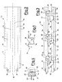
- a guide pair is formed of right and left guides for the two sides of a drawer. Said guides are substantially specular along a median line 16, formed substantially like the letter Z and united at the lower end of the Z. In particular, the upper part 12, inclined edge 11, side part (13) and lower part (14) will appear.
- Said pair is made by cutting a strip of sheet metal 17 symmetrical along the median line 16 so as to produce the flat part of the paired guides, performing optional operations of drawing and drilling of holes 15 for reception, for example, of stops, wheels, etc., which are known and readily imagined by those skilled in the art, and finally bending the strip along longitudinal lines (shown in broken lines in FIG. 2).
- the part 14 has a width substantially equal to the thickness of the drawer shoulders to which the guides are fixed.
- the paired guides are separated by cutting as shown in FIG. 3 along a line with lengths 18 coinciding with the median line 16 and lengths forming a plurality of tabs 19 in one guide with corresponding recesses 20 in the other.
- the length of the tabs 19 and hence of the corresponding recessed 20 is slightly less than the width of the lower part 14 so that they are completely contained in the latter.
- guides which can be fixed to a shoulder of a drawer by clipping.
- the tabs 19 can be bent upward so as to clip the guide to the lower edge of a shoulder 22 of a drawer immediately beneath the bottom 23 of said drawer, the lower ends of the guides being formed to be bent substantially in the shape of the letter C with the inner side of the C formed by the bent tabs.
- the upper part of the guide provides a sliding track for wheels 25 supported by guides fixed to the furniture item 26.
- the initial cutting and bending machines can be used both to produce screw-mounted guides and rivetted guides with no modification.
- the only different operations are the final ones of cutting to separate the two guides of a pair and optionally coining and drilling.
- the type of fastening with the tabs 19 permits easy and rapid positioning of the guides and permits acceptance of a tolerance on the thickness of the drawer flank, ensuring in all cases optional fixing with no need to provide gripping teeth or the like on the side wall of the guide which, once mounted, would be visible.
- the length of the guide, the number and exact position of the tabs 19 are variable depending on the particular practical requirements, as is clear to those skilled in the art.
- the end corners of the tabs can be partially bent toward the shoulder to bite into the wood upon clipping so as to provide additional holding characteristics.
Landscapes
- Drawers Of Furniture (AREA)
- Auxiliary Devices For And Details Of Packaging Control (AREA)
- Bearings For Parts Moving Linearly (AREA)
- Electrical Discharge Machining, Electrochemical Machining, And Combined Machining (AREA)
- Magnetic Heads (AREA)
- Footwear And Its Accessory, Manufacturing Method And Apparatuses (AREA)
- Pressure Welding/Diffusion-Bonding (AREA)
Claims (8)
- Verfahren zur Herstellung eines Führungspaares, das zwecks Gleiten auf entsprechenden Gleitelementen, die an einem Möbelstück befestigt sind, seitlich in der Nähe der unteren Kanten der zwei Schultern einer Schublade angebracht wird, umfassend die Stufen:- des Drückens eines im wesentlichen U-förmigen Elementes, dessen obere Enden nach außen gebogen sind, aus einem Blechstreifen, um Stütz- und Führungsschienen für die Gleitelemente bereitzustellen, und- des Zerschneidens des U in der Mitte, um es in zwei spiegelbildliche Elemente zu zerteilen, die das Führungspaar bilden, wobei das verfahren dadurch gekennzeichnet ist, daß das Zerteilen der Führungsschienen des Paares entlang einer Bahn durchgeführt wird, die an mehreren Punkten die Symmetrielinie des U kreuzt, um auf jeder Führungsschiene eine Vielzahl von übergreifenden Lappen zu bilden, indem diese von der anderen Führung des Paares herausgetrennt werden, und daß die Lappen im wesentlichen entlang der Symmetrielinie nach oben biegsam sind, um ein Befestigen der Führung an der unteren Kante der Schulter zu ermöglichen, indem diese zwischen die übergreifenden Lappen und den entsprechenden senkrechten Arm des U geklammert wird.
- Verfahren nach Anspruch 1, dadurch gekennzeichnet, daß es zusätzlich den Arbeitsgang des Prägens von Nuten entlang der Biegelinien der übergreifenden Lappen umfaßt.
- Verfahren nach Anspruch 2, dadurch gekennzeichnet, daß es zusätzlich den Arbeitsschritt der Herstellung von Löchern an den Enden der auf die übergreifenden Lappen geprägten Nuten umfaßt.
- Führungspaar für Schubladen, bei dem jede Fuhrung eine Schiene für das Gleiten an der Seitenwand umfaßt und sich als ein Stück ausdehnt, das derartig entworfen wurde, daß es in die Form des Buchstaben C gebogen werden kann, um die untere Kante einer Schulter der Schublade zu umklammern, dadurch gekennzeichnet, daß das innere Ende des C die Form von mit Zwischenräumen angeordneten, übergreifenden Lappen besitzt, wobei jede Führung eine flache Erweiterung in Form einer im wesentlichen rechteckigen Kontur besitzt, aus der die übergreifenden Lappen herausragen, die durch das Ausschneiden eines einzelnen Stückes an Material entlang einer gestrichelten Linie hergestellt wurden, wobei die Erweiterungen der zwei Führungen des Führungspaares ineinander geschrieben sind.
- Führungspaar nach Anspruch 4, dadurch gekennzeichnet, daß die Schnittlinie, die die flache Erweiterung der zwei Führungen trennt, einen geraden Mittellinienbereich mit wechselnden ausgeschnittenen Bereichen umfaßt, die trapezförmige Vorsprünge von gegenüberliegenden Seiten bilden und die die Lappen charakterisieren.
- Führungspaar nach Anspruch 4, dadurch gekennzeichnet, daß die Lappen entlang Linien gebogen wurden, die aus Rillen bestehen, um das Biegen zu erleichtern.
- Führungspaar nach Anspruch 6, dadurch gekennzeichnet, daß sich am Ende der Rillen, durch die das Biegen erleichtert wird, Begrenzungslöcher für sie befinden.
- Führungspaar nach Anspruch 4, dadurch gekennzeichnet, daß die Enden der Ecken der übergreifenden Lappen zumindest teilweise in Richtung der Schulter gebogen sind, um in das Holz einzudringen, wenn sie geklammert werden, und so zusätzlichen Halt zu bieten.
Applications Claiming Priority (2)
| Application Number | Priority Date | Filing Date | Title |
|---|---|---|---|
| ITMI911788 | 1991-06-28 | ||
| ITMI911788A IT1248585B (it) | 1991-06-28 | 1991-06-28 | Guide per cassetti e metodo di produzione di esse |
Publications (2)
| Publication Number | Publication Date |
|---|---|
| EP0520539A1 EP0520539A1 (de) | 1992-12-30 |
| EP0520539B1 true EP0520539B1 (de) | 1995-08-30 |
Family
ID=11360228
Family Applications (1)
| Application Number | Title | Priority Date | Filing Date |
|---|---|---|---|
| EP92201636A Expired - Lifetime EP0520539B1 (de) | 1991-06-28 | 1992-06-05 | Schubladenführungen und Verfahren zur Herstellung |
Country Status (6)
| Country | Link |
|---|---|
| EP (1) | EP0520539B1 (de) |
| AT (1) | ATE126982T1 (de) |
| DE (1) | DE69204379T2 (de) |
| DK (1) | DK0520539T3 (de) |
| ES (1) | ES2076003T3 (de) |
| IT (1) | IT1248585B (de) |
Families Citing this family (4)
| Publication number | Priority date | Publication date | Assignee | Title |
|---|---|---|---|---|
| IT1275815B1 (it) * | 1995-10-27 | 1997-10-17 | Gi Emme S R L Di | Procedimento perfezionato per la tranciatura da nastro metallico di sbozzati destinati alla fabbricazione in automatico di componenti |
| DE19541767B4 (de) * | 1995-11-09 | 2004-09-23 | Grass Gmbh | Schubladenschiene und Verfahren zu deren Herstellung |
| IT1296574B1 (it) * | 1997-11-27 | 1999-07-14 | Gaetano Donatiello | Procedimento per la tranciatura di guide metalliche per cassetti |
| US6378967B1 (en) | 2000-08-29 | 2002-04-30 | Grass America, Inc. | Clamp-on drawer slide |
-
1991
- 1991-06-28 IT ITMI911788A patent/IT1248585B/it active IP Right Grant
-
1992
- 1992-06-05 ES ES92201636T patent/ES2076003T3/es not_active Expired - Lifetime
- 1992-06-05 DK DK92201636.5T patent/DK0520539T3/da active
- 1992-06-05 EP EP92201636A patent/EP0520539B1/de not_active Expired - Lifetime
- 1992-06-05 AT AT92201636T patent/ATE126982T1/de active
- 1992-06-05 DE DE69204379T patent/DE69204379T2/de not_active Expired - Fee Related
Also Published As
| Publication number | Publication date |
|---|---|
| ATE126982T1 (de) | 1995-09-15 |
| EP0520539A1 (de) | 1992-12-30 |
| DE69204379T2 (de) | 1996-04-18 |
| IT1248585B (it) | 1995-01-19 |
| ES2076003T3 (es) | 1995-10-16 |
| ITMI911788A0 (it) | 1991-06-28 |
| ITMI911788A1 (it) | 1992-12-28 |
| DE69204379D1 (de) | 1995-10-05 |
| DK0520539T3 (da) | 1995-09-18 |
Similar Documents
| Publication | Publication Date | Title |
|---|---|---|
| JPH0545754B2 (de) | ||
| EP0520539B1 (de) | Schubladenführungen und Verfahren zur Herstellung | |
| US3972109A (en) | Cutting fixture for spiral binders and method of manufacture | |
| US4620724A (en) | Binding strips for rectangular hole punched paper | |
| US20060242869A1 (en) | Sliding identifier for file folders | |
| US5119869A (en) | Method of producing a telescopic cover | |
| IT8223674A1 (it) | Disposizione di ceppo di freno | |
| CA2047651A1 (en) | Long tip hanging folder rods | |
| US4535502A (en) | Method of fabricating a base plate for a metal fitting, and stamping utilized in forming the base plate | |
| US3034559A (en) | Dies for bending sheet metal | |
| US5681101A (en) | Drawer slide and the method of producing it | |
| US7051567B2 (en) | Method for folding and curving of a metallic plate | |
| US5720565A (en) | Folder with fastener for keeping papers and documents | |
| US3037267A (en) | Method of making shelf structures | |
| US3798709A (en) | Faller bar | |
| US2515286A (en) | Clothes peg | |
| EP0082841B1 (de) | Werkzeug zum herstellen von nieten oder expansionsnägeln | |
| HUP0101506A2 (hu) | Bilincs, eljárás annak előállítására, valamint mezőgazdasági eszköz | |
| US6457226B1 (en) | Process for beading sheet metal parts in a beading machine | |
| KR900006758Y1 (ko) | 플라스틱 편철구(編綴具) | |
| JP4706989B1 (ja) | 綴じ用具 | |
| EP1462663B1 (de) | Klammer | |
| JPS6031542Y2 (ja) | 物置棚用裏板の取付け装置 | |
| KR950001094B1 (ko) | 손톱깍기용 지렛대판의 성형방법 | |
| KR960004372Y1 (ko) | 전자렌지의 도어프레임 절곡구조 |
Legal Events
| Date | Code | Title | Description |
|---|---|---|---|
| PUAI | Public reference made under article 153(3) epc to a published international application that has entered the european phase |
Free format text: ORIGINAL CODE: 0009012 |
|
| AK | Designated contracting states |
Kind code of ref document: A1 Designated state(s): AT BE CH DE DK ES FR GB GR IT LI LU MC NL PT SE |
|
| 17P | Request for examination filed |
Effective date: 19930601 |
|
| 17Q | First examination report despatched |
Effective date: 19941111 |
|
| GRAA | (expected) grant |
Free format text: ORIGINAL CODE: 0009210 |
|
| AK | Designated contracting states |
Kind code of ref document: B1 Designated state(s): AT BE CH DE DK ES FR GB GR IT LI LU MC NL PT SE |
|
| PG25 | Lapsed in a contracting state [announced via postgrant information from national office to epo] |
Ref country code: IT Free format text: LAPSE BECAUSE OF FAILURE TO SUBMIT A TRANSLATION OF THE DESCRIPTION OR TO PAY THE FEE WITHIN THE PRE;WARNING: LAPSES OF ITALIAN PATENTS WITH EFFECTIVE DATE BEFORE 2007 MAY HAVE OCCURRED AT ANY TIME BEFORE 2007. THE CORRECT EFFECTIVE DATE MAY BE DIFFERENT FROM THE ONE RECORDED.SCRIBED TIME-LIMIT Effective date: 19950830 Ref country code: LI Effective date: 19950830 Ref country code: GR Free format text: LAPSE BECAUSE OF FAILURE TO SUBMIT A TRANSLATION OF THE DESCRIPTION OR TO PAY THE FEE WITHIN THE PRESCRIBED TIME-LIMIT Effective date: 19950830 Ref country code: MC Free format text: LAPSE BECAUSE OF NON-PAYMENT OF DUE FEES Effective date: 19950830 Ref country code: AT Effective date: 19950830 Ref country code: CH Effective date: 19950830 |
|
| REF | Corresponds to: |
Ref document number: 126982 Country of ref document: AT Date of ref document: 19950915 Kind code of ref document: T |
|
| REG | Reference to a national code |
Ref country code: DK Ref legal event code: T3 |
|
| REF | Corresponds to: |
Ref document number: 69204379 Country of ref document: DE Date of ref document: 19951005 |
|
| ET | Fr: translation filed | ||
| REG | Reference to a national code |
Ref country code: ES Ref legal event code: FG2A Ref document number: 2076003 Country of ref document: ES Kind code of ref document: T3 |
|
| REG | Reference to a national code |
Ref country code: CH Ref legal event code: PL |
|
| SC4A | Pt: translation is available |
Free format text: 951127 AVAILABILITY OF NATIONAL TRANSLATION |
|
| PLAV | Examination of admissibility of opposition |
Free format text: ORIGINAL CODE: EPIDOS OPEX |
|
| PLBQ | Unpublished change to opponent data |
Free format text: ORIGINAL CODE: EPIDOS OPPO |
|
| PLBI | Opposition filed |
Free format text: ORIGINAL CODE: 0009260 |
|
| PG25 | Lapsed in a contracting state [announced via postgrant information from national office to epo] |
Ref country code: LU Free format text: LAPSE BECAUSE OF NON-PAYMENT OF DUE FEES Effective date: 19960630 |
|
| PLBF | Reply of patent proprietor to notice(s) of opposition |
Free format text: ORIGINAL CODE: EPIDOS OBSO |
|
| 26 | Opposition filed |
Opponent name: FORMENTI & GIOVENZANA S.P.A. Effective date: 19960529 |
|
| NLR1 | Nl: opposition has been filed with the epo |
Opponent name: FORMENTI & GIOVENZANA S.P.A. |
|
| PLBF | Reply of patent proprietor to notice(s) of opposition |
Free format text: ORIGINAL CODE: EPIDOS OBSO |
|
| PLBO | Opposition rejected |
Free format text: ORIGINAL CODE: EPIDOS REJO |
|
| APAC | Appeal dossier modified |
Free format text: ORIGINAL CODE: EPIDOS NOAPO |
|
| APAE | Appeal reference modified |
Free format text: ORIGINAL CODE: EPIDOS REFNO |
|
| APAC | Appeal dossier modified |
Free format text: ORIGINAL CODE: EPIDOS NOAPO |
|
| PGFP | Annual fee paid to national office [announced via postgrant information from national office to epo] |
Ref country code: FR Payment date: 19980520 Year of fee payment: 7 |
|
| PGFP | Annual fee paid to national office [announced via postgrant information from national office to epo] |
Ref country code: SE Payment date: 19980525 Year of fee payment: 7 |
|
| PGFP | Annual fee paid to national office [announced via postgrant information from national office to epo] |
Ref country code: PT Payment date: 19980526 Year of fee payment: 7 |
|
| PGFP | Annual fee paid to national office [announced via postgrant information from national office to epo] |
Ref country code: BE Payment date: 19980604 Year of fee payment: 7 |
|
| PGFP | Annual fee paid to national office [announced via postgrant information from national office to epo] |
Ref country code: DK Payment date: 19980615 Year of fee payment: 7 |
|
| PGFP | Annual fee paid to national office [announced via postgrant information from national office to epo] |
Ref country code: NL Payment date: 19980630 Year of fee payment: 7 |
|
| PG25 | Lapsed in a contracting state [announced via postgrant information from national office to epo] |
Ref country code: DK Free format text: LAPSE BECAUSE OF NON-PAYMENT OF DUE FEES Effective date: 19990605 |
|
| PG25 | Lapsed in a contracting state [announced via postgrant information from national office to epo] |
Ref country code: SE Free format text: THE PATENT HAS BEEN ANNULLED BY A DECISION OF A NATIONAL AUTHORITY Effective date: 19990629 |
|
| PG25 | Lapsed in a contracting state [announced via postgrant information from national office to epo] |
Ref country code: BE Free format text: LAPSE BECAUSE OF NON-PAYMENT OF DUE FEES Effective date: 19990630 Ref country code: FR Free format text: THE PATENT HAS BEEN ANNULLED BY A DECISION OF A NATIONAL AUTHORITY Effective date: 19990630 |
|
| BERE | Be: lapsed |
Owner name: F 40 S.P.A. Effective date: 19990630 |
|
| PG25 | Lapsed in a contracting state [announced via postgrant information from national office to epo] |
Ref country code: PT Free format text: LAPSE BECAUSE OF NON-PAYMENT OF DUE FEES Effective date: 19991231 |
|
| PG25 | Lapsed in a contracting state [announced via postgrant information from national office to epo] |
Ref country code: NL Free format text: LAPSE BECAUSE OF NON-PAYMENT OF DUE FEES Effective date: 20000101 |
|
| EUG | Se: european patent has lapsed |
Ref document number: 92201636.5 |
|
| NLV4 | Nl: lapsed or anulled due to non-payment of the annual fee |
Effective date: 20000101 |
|
| REG | Reference to a national code |
Ref country code: DK Ref legal event code: EBP |
|
| REG | Reference to a national code |
Ref country code: PT Ref legal event code: MM4A Free format text: LAPSE DUE TO NON-PAYMENT OF FEES Effective date: 19991231 |
|
| APAC | Appeal dossier modified |
Free format text: ORIGINAL CODE: EPIDOS NOAPO |
|
| PLBN | Opposition rejected |
Free format text: ORIGINAL CODE: 0009273 |
|
| STAA | Information on the status of an ep patent application or granted ep patent |
Free format text: STATUS: OPPOSITION REJECTED |
|
| REG | Reference to a national code |
Ref country code: FR Ref legal event code: ST |
|
| 27O | Opposition rejected |
Effective date: 20000526 |
|
| REG | Reference to a national code |
Ref country code: GB Ref legal event code: IF02 |
|
| APAH | Appeal reference modified |
Free format text: ORIGINAL CODE: EPIDOSCREFNO |
|
| PGFP | Annual fee paid to national office [announced via postgrant information from national office to epo] |
Ref country code: ES Payment date: 20080523 Year of fee payment: 17 |
|
| PGFP | Annual fee paid to national office [announced via postgrant information from national office to epo] |
Ref country code: DE Payment date: 20080530 Year of fee payment: 17 |
|
| PGFP | Annual fee paid to national office [announced via postgrant information from national office to epo] |
Ref country code: GB Payment date: 20080522 Year of fee payment: 17 |
|
| GBPC | Gb: european patent ceased through non-payment of renewal fee |
Effective date: 20090605 |
|
| PG25 | Lapsed in a contracting state [announced via postgrant information from national office to epo] |
Ref country code: GB Free format text: LAPSE BECAUSE OF NON-PAYMENT OF DUE FEES Effective date: 20090605 |
|
| PG25 | Lapsed in a contracting state [announced via postgrant information from national office to epo] |
Ref country code: DE Free format text: LAPSE BECAUSE OF NON-PAYMENT OF DUE FEES Effective date: 20100101 |
|
| REG | Reference to a national code |
Ref country code: ES Ref legal event code: FD2A Effective date: 20090606 |
|
| PG25 | Lapsed in a contracting state [announced via postgrant information from national office to epo] |
Ref country code: ES Free format text: LAPSE BECAUSE OF NON-PAYMENT OF DUE FEES Effective date: 20090606 |