EP0519490A2 - Steuerungsanordnung für Eingangs-Ausgangssignale - Google Patents
Steuerungsanordnung für Eingangs-Ausgangssignale Download PDFInfo
- Publication number
- EP0519490A2 EP0519490A2 EP92110361A EP92110361A EP0519490A2 EP 0519490 A2 EP0519490 A2 EP 0519490A2 EP 92110361 A EP92110361 A EP 92110361A EP 92110361 A EP92110361 A EP 92110361A EP 0519490 A2 EP0519490 A2 EP 0519490A2
- Authority
- EP
- European Patent Office
- Prior art keywords
- signal
- input
- unit
- selector
- data
- Prior art date
- Legal status (The legal status is an assumption and is not a legal conclusion. Google has not performed a legal analysis and makes no representation as to the accuracy of the status listed.)
- Granted
Links
Images


Classifications
-
- H—ELECTRICITY
- H04—ELECTRIC COMMUNICATION TECHNIQUE
- H04J—MULTIPLEX COMMUNICATION
- H04J3/00—Time-division multiplex systems
- H04J3/02—Details
- H04J3/06—Synchronising arrangements
- H04J3/062—Synchronisation of signals having the same nominal but fluctuating bit rates, e.g. using buffers
- H04J3/0632—Synchronisation of packets and cells, e.g. transmission of voice via a packet network, circuit emulation service [CES]
-
- H—ELECTRICITY
- H04—ELECTRIC COMMUNICATION TECHNIQUE
- H04L—TRANSMISSION OF DIGITAL INFORMATION, e.g. TELEGRAPHIC COMMUNICATION
- H04L12/00—Data switching networks
- H04L12/28—Data switching networks characterised by path configuration, e.g. LAN [Local Area Networks] or WAN [Wide Area Networks]
- H04L12/42—Loop networks
- H04L12/427—Loop networks with decentralised control
Definitions
- the present invention relates to an input-output signal control apparatus, and more particularly, in ATM communication or a high speed packet communication in a broad-band ISDN, to an input-output signal control apparatus for inserting data from a plurality of input ports into designated time slots and for outputting them as a main signal from a single output port.
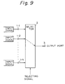
- a conventional control apparatus for selecting an output signal of an ATM apparatus and so forth has a construction in which a selector unit receives various input signals from input ports, and in response to a selecting signal applied to the selector unit, a connection and a switching are carried out so that the selected signal is output as a main signal from an output port 3.
- the present invention has an object to resolve the above disadvantage, and has an object to provide an input-output signal control apparatus in which, the selection of various signals from input ports and the insertion of the signals into time slots are effected synchronous with a synchronizing signal so that the input signals are output in the form of trued up phases.
- an input-output signal control apparatus for receiving input signals through a plurality of input ports, respectively, and for converting the received input signals into a main signal synchronized with a sequence of time slots.
- the main signal is output through a main signal line from a single output port.
- the apparatus comprises a control data generating unit for generating control data for designating input signals to be output in synchronization with the sequence of time slots, and a plurality of selector units connected to the plurality of input ports, respectively, and connected in series between the control data generating unit and the output port, for selecting, in accordance with the control data, input signals to be output through the main signal line in synchronization with the time slots so as to obtain the main signal at the output port.
- each of the selector units detects each of the time slots by a signal in the control data in each of the time slots.
- control signal generating unit further generates a synchronizing signal synchronized with the control data, and that each of the selector units detects each of the time slots by receiving the synchronizing signal.
- control data include, in each of the time slots, a selecting signal for designating one of the selector units, and each of the selector units comprises a determining unit for determining, at every time that the selecting signal is received, whether or not the selector unit, including the determining unit, is designated by the selecting signal, wherein, when the determining unit determines that the selector unit is designated by the selecting signal, the input signal from the corresponding input port is output to the main signal line in synchronization with the time slot of the selecting signal, and when the determining unit determines that the selector unit is not designated by the selecting signal, the data on the main signal line in the time slot of the selecting signal is passed through the selector unit in question without change.
- control signal generating unit further generates cells in synchronization with the time slots.
- Each of the selector units (5-i) further comprises a data passing/rewriting unit operatively connected to the determining unit for writing the selected input signal into the cell of the input time slot when the determining unit determines that the selector unit is designated by the selecting signal, and for passing the cell of the input time slot without change when the determining unit determines that the selector unit is not designated by said selecting signal.
- the selected input signals are written into the cells of the receiving time slots.
- the selected input signals are written into the cells of the next time slots of the receiving time slots.
- the cells generated by the control data generating unit are empty cells.
- At least one of the cells generated by the control data generating unit include valid data, and the control data are so formed that the valid data are not rewritten by the input signal.
- control data generated from the control data generating unit include a data enable control signal and a sequence of cells; the data enable control signal having a flag in a time slot when an input signal has already been written in the cell of the time slot, and each of the cells possibly including, in each of the time slots, a selecting signal for designating one of the selector units, wherein when the selector signal designates the selector unit in question and when a flag is not established in the time slot of the data enable control signal, the selector unit in question writes an input signal into the cell of the input time slot and establishes a flag in the data enable control signal of the input time slot, and when the selector signal does not designate the selector unit in question or when the flag is established in the time slot of the data enable control signal, the corresponding cell is passed through the selector unit in question.
- each of the selector units comprises a determining unit for determining, at every time when the selecting signal is received, whether or not the selector unit, including the determining unit, is designated by the selecting signal and the data enable control signal, and for generating a flag establishing signal when the own selector unit is determined to be designated, a data passing/rewriting unit, operatively connected to the determining unit, for writing the selected input signal into the cell of the input time slot when the determining unit determines that the selector unit is designated by the selecting signal, and for passing the cell of the input time slot without change when the determining unit determines that the own selector unit is not designated by the selecting signal, a flag describing unit, operatively connected to the determining unit and the control data generating unit, for establishing a flag in the data enable control signal in synchronization with a time slot, when the input signal is written in a cell of the time slot in response to the flag establishing signal, whereby when a flag is established in a time slot of the data
- a conventional input-output control apparatus is first described with reference to Fig. 9, in which a selector unit 2 receives various input signals from input ports 1-1 to 1-N, and in response to a selecting signal that is input to the selector unit 2, a connection and a switching are carried out so that the selected signal is output as a main signal from a single output port 3.
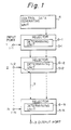
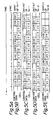
- Figure 1 is a principal constructional diagram of an input-output signal control apparatus according to the present invention.
- 1-1 to 1-N represent input ports to which input signals are applied
- 3 is a single output port for outputting a main signal in which selected input signals are inserted.
- the main signal is in synchronization with a sequence of time slots.
- Reference numeral 4 is a control data generating unit for synchronously outputting control data for designating the input signals to be output in synchronization with the sequence of time slots.
- References 5-1 to 5-N are selector units connected to the input ports 1-1 to 1-N, respectively, and connected in series between the control data generating unit 4 and the output port, for selecting, in accordance with the control data, input signals to be output through a main signal line 7 in synchronization with the time slots so as to obtain the main signal at the output port 3.
- the selector unit 1-1 when the selector unit 1-1 is designated by the above-mentioned control data, the input signal from the corresponding input port 1-1 is output in synchronization with the time slot of the control data from the control data generating unit 4.
- the time slot is output from the selector unit 1-1 as an empty signal.
- the selector unit 1-2 is designated by the above-mentioned control data
- the input signal from the corresponding input port 1-2 is output in synchronization with the time slot of the control data from the control data generating unit 4.
- the selector unit 1-2 is not designated, the data stored in the time slot from the previous stage selector unit 5-1 is passed to the next stage selector unit 5-3 through the main signal line 7 without change.
- the input signals are inserted into time slots or are not inserted into time slots depending on the control data.
- the main signal can be obtained at the output port 3.
- References 6-1 to 6-N are determining units each for decoding the control data from the control data generating unit 4 to determine whether or not the selector unit 5-i in question, i.e., the selector unit including the determining unit 6-i, is designated.
- each selector unit 5-i when the selector unit 5-i is designated, the data from the corresponding input port 1-i is selected to be output to a time slot in synchronization with the sequence of time slots.
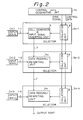
- FIG. 2 is a block diagram of an input-output signal control apparatus according to an embodiment of the present invention.
- Reference symbol 4a is a control data generating unit which, in this embodiment, generates a synchronizing signal SYNC and control data that is in synchronization with the synchronizing signal.
- a first selector unit 5a-1 includes a collation unit 8 and a cell generator and input signal inserting unit 9.
- the synchronizing signal SYNC is shown in Fig. 5A, and an example of the control data generated from the control data generating unit 4a and the cells generated by the unit 9 are shown in Fig. 5B.
- Each of the selector units 5a-2 to 5a-N includes a collation unit 8 and a data passing/rewriting unit 9a.
- the control data includes names of channels CH1, CH2, CH3, ... in desired time slots, respectively as shown in the upper sides in Figs. 5B, 5C, 5D, and 5E. These time slots are in synchronization with the synchronizing signal SYNC.
- the cell generator and input signal inserting unit 9 generates a sequence of empty cells C1, C2, C3, ... in the respective time slots are shown in the lower side in Fig. 5B.
- the empty cells C1, C2, C3, ... are generated by the cell generator in the unit 9 but are not generated by the control data generating unit 4a.
- the empty cells C1, C2, C3, ... are also synchronized with the synchronizing signal SYNC.
- the synchronization signal and the control data are passed through the collation units 8 in all of the selector units 5a-1 to 5a-N.
- the input signal from the corresponding input port 1-i is written on the cell of the time slot when the channel CHi is detected.
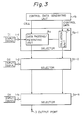
- FIG. 3 is a block diagram of an input-output signal control apparatus according to another embodiment of the present invention.
- a control data generating unit 4b generates the control data as well as cells
- a first selector unit 5b-1 does not include the cell generator and the input signal inserting unit but has the same construction as the remaining selector units 5b-2 to 5b-N including a collation unit 8a and a data passing/rewriting unit 9a
- the control data generating unit 4b does not generate the synchronizing signal SYNC.
- the cells may be empty cells or valid data storing cells.
- the valid data storing cells may be, for example, supervising cells for supervising the apparatus.
- synchronization is carried out by a predetermined signal in the control data in each time slot.
- the data passing/rewriting unit 9a writes the input signal from the input port 1-i on the cell of the time slot synchronously transmitted to the selector unit 5b-i. Namely, the data in the cell of the time slot is rewritten by the input signal Di.
- the cell of the time slot in which the input signal Di has been written is output from the selector unit 5-i to the next stage selector unit 5-(i + 1).
- the data passing/rewriting unit 9a does not write on the cell of the time slot synchronously transmitted to the selector unit 5-i, but passes the data stored in the cell of the time slot through said selector unit 5-i without change.
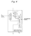
- Figure 4 shows a construction of an embodiment of the data passing/rewriting unit 9a in the selector unit 5b-i in Fig. 3.
- 10 and 11 are registers, and 12 is an output control unit.
- the input signal Di from the input port 1-i is set.
- the input signal Di set in the register 10 or the data stored in a cell of a time slot synchronously sent to the selector unit 5b-i is stored. Namely, in the register 11, either the cell data from the cell control data generating unit 4b, or the input signal from the input port 1, which is to be written over the cell, is stored.
- the output control unit 12 controls the output of the register 10 in which the input signal Di is stored and also controls the output of the register 11 in which the data of the time slot of the cell from the control data generating unit 4b is stored, as follows. Namely, when the collation unit 8a determines that the selector unit 5-i in question is being designated, the data of the time slot stored in the register 11 is rewritten by the input signal Di set in the register 10, and then the data of the time slot stored in the register 11, i.e., the input signal Di is output from the selector unit 5-i in question.
- the collation unit 8a determines that the selector unit 5-i in question is not designated, the data of the time slot stored in the register 11 is output from the selector unit 5-i in question without any change.
- Figures 5A to 5D are time charts explaining the operation of the apparatus shown in Fig. 3.
- Fig. 5A shows the synchronizing signal used in the embodiment shown in Fig. 2.
- the synchronizing signal SYNC is not generated from the control data generating unit 4b but the synchronization is carried out by using a signal in each time slot of the control data CH1, CH2, ....
- Fig. 5B shows control data and cells input to the selector unit 5b-1.
- the control data generating unit 4b generates control data CH1, CHN, null, CH2, ... and empty cells C1, C2, C3, ... in synchronization with respective time slots.
- the selector unit 5b-1 when the control data CH1 is detected, the selector unit 5-1 inserts the input signal D1 from the input port 1-1 into the empty cell C1 of the time slot of the main signal that is input synchronously with the control data CH1.
- the main signal including the input signal D1 and the remaining empty cells C2, C3, ... are output.
- time lag between the control data shown in Fig. 5B and the control data shown in Fig. 5C is a delay time between the input and the output of the selector unit 5b-1.
- the input signal D1 is inserted into a receiving time slot.
- the input signal D2 from the input port 1-2 is inserted into the time slot of the empty cell of the main signal that is input synchronously with the control data CH2.
- the main signal indicated in Fig. 5E which is a sequence of input signals and empty cells, is output in such a way that the respective input signals D1, DN, D2 are inserted, synchronously with the control data in the time slots of the empty cells corresponding to the channels designated by the control data.
- the input signal from the input port designated by the control data is written on a receiving time slot of an empty cell that is input synchronously with the control data in question.
- the signal data may be written on the time slot of an empty cell that is input synchronously with the next control data, as shown in Figs. 6A to 6D.
- the output control unit 12 immediately writes the input signal Di set in the register 10 onto the data in the empty cell of the next tame slot stored in the register 11, and the data is output from the selector unit 5b-i in question.
- control data CH1 and an empty cell C1 of a time slot synchronously with the control data CH1 are output from the control data generating unit 4b as shown in Fig. 6A, the input signal D1 from the input port 1-1 is inserted, in the selector unit 5b-1, into the time slot of an empty cell of the main signal that is input synchronously with the next control data CHN followed by the control data CH1.
- the input signal D2 from the input port 1-2 is inserted, in the selector unit 5b-2, into the time slot of an empty cell of the main signal that is input synchronously with the next control data followed by the control data CH2, as shown in Fig. 6C.
- control signals i.e., the main signal indicated in Fig. 6D, which includes respective input signals D1, D2, ..., DN from the input ports and are inserted, synchronously with the control data in the time slots of the next empty cells corresponding to the channels designated by the control data, are output.
- the control data includes null data in one or more time slots, and the cells corresponding to the null data are not rewritten by the input signals. Therefore, in such cells corresponding to the null data, valid data such as apparatus supervising data may be previously inserted in the control data generating unit 4b.
- FIG. 7 is a block diagram of an input-output signal control apparatus according to still another embodiment of the present invention.
- reference 13 is a control data generating unit for outputting a main signal and a data enable signal.
- control data CH1, CHN, CH2, ... and empty cells are inserted in a sequence.
- the data enable control signal is used to indicate whether or not an input signal from an input port 1-i has been inserted in the empty cell in question.
- 14 is a flag describing unit for establishing, when an input signal from the input port 1-i is written into a time slot of an empty cell in the data passing/rewriting unit 9, a flag in synchronization with the time slot of the empty cell in question, in the data enable control signal.
- determining unit 15 is a determining unit for determining whether or not the selector unit is designated based on the control data stored in the empty cell of the input time slot and the data enable control synchronous with the time slot of the empty cell in question, and for establishing, when it is determined that the own selector is being designated, a flag in the above-mentioned data enable control signal.
- the control data stored in the empty cell of the time slot, in which the flag is not established is checked and, when the selector unit 5-i belonging to the determining unit 15 in question is designated, the determining unit 15 outputs a signal instructing a rewrite of the control data stored in the empty cell of the time slot in question input to the data passing/rewriting unit 9 by the input signal CHi from the input port 1-i.
- the determining unit 15 outputs a signal to disable the flag describing unit 14 by establishing a data enable control signal flag synchronously with the time slot in question.
- Figs. 8A to 8D are time charts explaining the operation of the apparatus shown in Fig. 7.
- the main signal including empty cells EC and cells storing control data CH1, CHN, CH2, ..., and the data enable control signal are output from the control data generating unit 13.
- the selector unit 5c-1 when the control data CH1 is detected and when a flag "1" is not established in the time slot corresponding to the control data CH1, the input signal D1 from the input port 1-1 is inserted into the time slot of the cell in which the control data CH1 designating the selector unit 5-1 is stored as shown in Fig. 8B.
- a flag "1" is established at a position synchronously with the time slot on which the input signal CH1 from the input port 1 in question has been written.
- the selector unit 5c-2 when the control data CH2 is detected in the control data and when the above-mentioned flag is not established in the time slot of the input data enable control line corresponding to the control data CH2, the input signal D2 from the input port 1-2 is inserted into the time slot of cell storing the control data CH2, and a flag "1" is established in the corresponding time slot of the data enable control signal as shown in Fig. 8C.
- the main signal in which the various input signals from the input ports designated by the control data are stored in the cells in respective time slots, is output as shown in Fig. 8D.
- the data enable control signal line can be a single line. Also, the control data and the calls can be sent by a single line.
- each selector unit does not have the above-mentioned memory and memory control unit, but a single memory and a single memory control unit are provided for all selector units, and the operation is substantially the same as when each selector unit is provided with the data passing/rewriting unit.
- the main signal in which the signal data are inserted in the time slot, have trued up phases.
Landscapes
- Engineering & Computer Science (AREA)
- Computer Networks & Wireless Communication (AREA)
- Signal Processing (AREA)
- Multimedia (AREA)
- Computer Hardware Design (AREA)
- Time-Division Multiplex Systems (AREA)
- Data Exchanges In Wide-Area Networks (AREA)
- Use Of Switch Circuits For Exchanges And Methods Of Control Of Multiplex Exchanges (AREA)
Applications Claiming Priority (2)
| Application Number | Priority Date | Filing Date | Title |
|---|---|---|---|
| JP149089/91 | 1991-06-21 | ||
| JP3149089A JPH0530127A (ja) | 1991-06-21 | 1991-06-21 | 出力信号制御方式 |
Publications (3)
| Publication Number | Publication Date |
|---|---|
| EP0519490A2 true EP0519490A2 (de) | 1992-12-23 |
| EP0519490A3 EP0519490A3 (en) | 1993-01-13 |
| EP0519490B1 EP0519490B1 (de) | 1997-11-05 |
Family
ID=15467461
Family Applications (1)
| Application Number | Title | Priority Date | Filing Date |
|---|---|---|---|
| EP92110361A Expired - Lifetime EP0519490B1 (de) | 1991-06-21 | 1992-06-19 | Steuerungsanordnung für Eingangs-Ausgangssignale |
Country Status (5)
| Country | Link |
|---|---|
| US (1) | US5359604A (de) |
| EP (1) | EP0519490B1 (de) |
| JP (1) | JPH0530127A (de) |
| CA (1) | CA2071616C (de) |
| DE (1) | DE69222984T2 (de) |
Families Citing this family (2)
| Publication number | Priority date | Publication date | Assignee | Title |
|---|---|---|---|---|
| TWI426388B (zh) | 2010-05-20 | 2014-02-11 | Nuvoton Technology Corp | 超級輸入輸出模組、電腦系統及其控制方法 |
| CN115087876A (zh) * | 2020-02-28 | 2022-09-20 | 索尼半导体解决方案公司 | 半导体装置和测试系统 |
Family Cites Families (9)
| Publication number | Priority date | Publication date | Assignee | Title |
|---|---|---|---|---|
| US3755786A (en) * | 1972-04-27 | 1973-08-28 | Ibm | Serial loop data transmission system |
| JPS56152352A (en) * | 1980-04-25 | 1981-11-25 | Hitachi Ltd | Data transmission system |
| US4389721A (en) * | 1981-06-30 | 1983-06-21 | Harris Corporation | Time-division multiplex serial loop |
| JPS6330034A (ja) * | 1986-07-23 | 1988-02-08 | Nec Corp | 多重化回路 |
| US4821258A (en) * | 1986-08-06 | 1989-04-11 | American Telephone And Telegraph Company At&T Bell Laboratories | Crosspoint circuitry for data packet space division switches |
| US4817082A (en) * | 1987-03-09 | 1989-03-28 | American Telephone And Telegraph Company, At&T Bell Laboratories | Crosspoint switching system using control rings with fast token circulation |
| JP2604385B2 (ja) * | 1987-08-28 | 1997-04-30 | 株式会社日立製作所 | ディジタル信号の多重化方法及び装置 |
| JP2760797B2 (ja) * | 1988-03-18 | 1998-06-04 | 株式会社日立製作所 | ディジタル信号の多重化方法 |
| JP2825093B2 (ja) * | 1988-06-21 | 1998-11-18 | 富士通株式会社 | 通信データ行先制御方式 |
-
1991
- 1991-06-21 JP JP3149089A patent/JPH0530127A/ja active Pending
-
1992
- 1992-06-18 CA CA002071616A patent/CA2071616C/en not_active Expired - Lifetime
- 1992-06-19 DE DE69222984T patent/DE69222984T2/de not_active Expired - Lifetime
- 1992-06-19 EP EP92110361A patent/EP0519490B1/de not_active Expired - Lifetime
- 1992-06-22 US US07/902,596 patent/US5359604A/en not_active Expired - Lifetime
Also Published As
| Publication number | Publication date |
|---|---|
| CA2071616A1 (en) | 1992-12-22 |
| EP0519490B1 (de) | 1997-11-05 |
| EP0519490A3 (en) | 1993-01-13 |
| US5359604A (en) | 1994-10-25 |
| CA2071616C (en) | 1999-05-25 |
| DE69222984D1 (de) | 1997-12-11 |
| DE69222984T2 (de) | 1998-03-26 |
| JPH0530127A (ja) | 1993-02-05 |
Similar Documents
| Publication | Publication Date | Title |
|---|---|---|
| EP0323248B1 (de) | Zeitmultiplexvermittlung für Mehrkanal-Verbindungen, welche zwei Zeitvermittlungsspeicher als Rahmenausgleicher verwendet | |
| US5577037A (en) | Method of processing inclusively STM signals and ATM signals and switching system employing the same | |
| EP0418813A2 (de) | Verfahren und System zur Leitweglenkung für ein aus einer Mehrzahl von Wegen bestehendes Vermittlunssystem | |
| AU652446B2 (en) | Switching network for switching nodes of a communication network | |
| US6775294B2 (en) | Time slot assigner for communication system | |
| US8711889B2 (en) | Asynchronous line interface rate adaptation to the physical layer with synchronous lines at the connection layer | |
| US5654967A (en) | Delay-in-frames correcting system in a PCM transmission line | |
| US5509013A (en) | Multiplexer control system | |
| US5040174A (en) | Time division speech path apparatus | |
| US5359604A (en) | Input-output signal control apparatus | |
| EP0543327B1 (de) | Synchrones optisches Multiplexsystem | |
| US5287360A (en) | Device for inserting information bits into a specific frame structure | |
| US6535479B1 (en) | Hitless switching system of ATM switch apparatus in which discard priority control is stopped | |
| JP2804126B2 (ja) | フレーム位相変換方法および信号伝送方法 | |
| US6392991B1 (en) | Communication network, node apparatus used in the network, and their control method | |
| US7031351B2 (en) | Serial data mapping apparatus for synchronous digital hierarchy | |
| KR100226540B1 (ko) | Atm 스위치의 어드레스 생성 회로 | |
| US6948030B1 (en) | FIFO memory system and method | |
| JP2000032575A (ja) | Tone及びDTMF発生機能を備えたATMセル変換装置及びその方法 | |
| EP0606609A2 (de) | Vorrichtung und Verfahren zur Rahmenphasensynchronisierung und Vorrichtung zur Phasensynchronisierung für TDM Rahmen | |
| GB2323503A (en) | ATM cell synchronisation circuit | |
| KR0168921B1 (ko) | 동기식 전송시스템에서 시험액세스를 위한 24x3교차 스위치 회로 | |
| US6556566B1 (en) | Time division switch with inserter and dropper using external memory and time division switching method | |
| JP2601219B2 (ja) | 多重化装置 | |
| JP2604965B2 (ja) | パス監視ビット抽出装置 |
Legal Events
| Date | Code | Title | Description |
|---|---|---|---|
| PUAI | Public reference made under article 153(3) epc to a published international application that has entered the european phase |
Free format text: ORIGINAL CODE: 0009012 |
|
| PUAL | Search report despatched |
Free format text: ORIGINAL CODE: 0009013 |
|
| AK | Designated contracting states |
Kind code of ref document: A2 Designated state(s): DE FR GB |
|
| AK | Designated contracting states |
Kind code of ref document: A3 Designated state(s): DE FR GB |
|
| 17P | Request for examination filed |
Effective date: 19930706 |
|
| 17Q | First examination report despatched |
Effective date: 19951106 |
|
| GRAG | Despatch of communication of intention to grant |
Free format text: ORIGINAL CODE: EPIDOS AGRA |
|
| GRAH | Despatch of communication of intention to grant a patent |
Free format text: ORIGINAL CODE: EPIDOS IGRA |
|
| GRAH | Despatch of communication of intention to grant a patent |
Free format text: ORIGINAL CODE: EPIDOS IGRA |
|
| GRAA | (expected) grant |
Free format text: ORIGINAL CODE: 0009210 |
|
| AK | Designated contracting states |
Kind code of ref document: B1 Designated state(s): DE FR GB |
|
| PG25 | Lapsed in a contracting state [announced via postgrant information from national office to epo] |
Ref country code: FR Free format text: LAPSE BECAUSE OF FAILURE TO SUBMIT A TRANSLATION OF THE DESCRIPTION OR TO PAY THE FEE WITHIN THE PRESCRIBED TIME-LIMIT Effective date: 19971105 |
|
| REF | Corresponds to: |
Ref document number: 69222984 Country of ref document: DE Date of ref document: 19971211 |
|
| EN | Fr: translation not filed | ||
| PLBE | No opposition filed within time limit |
Free format text: ORIGINAL CODE: 0009261 |
|
| STAA | Information on the status of an ep patent application or granted ep patent |
Free format text: STATUS: NO OPPOSITION FILED WITHIN TIME LIMIT |
|
| 26N | No opposition filed | ||
| REG | Reference to a national code |
Ref country code: GB Ref legal event code: IF02 |
|
| PGFP | Annual fee paid to national office [announced via postgrant information from national office to epo] |
Ref country code: GB Payment date: 20110615 Year of fee payment: 20 |
|
| PGFP | Annual fee paid to national office [announced via postgrant information from national office to epo] |
Ref country code: DE Payment date: 20110615 Year of fee payment: 20 |
|
| REG | Reference to a national code |
Ref country code: DE Ref legal event code: R071 Ref document number: 69222984 Country of ref document: DE |
|
| REG | Reference to a national code |
Ref country code: DE Ref legal event code: R071 Ref document number: 69222984 Country of ref document: DE |
|
| REG | Reference to a national code |
Ref country code: GB Ref legal event code: PE20 Expiry date: 20120618 |
|
| PG25 | Lapsed in a contracting state [announced via postgrant information from national office to epo] |
Ref country code: DE Free format text: LAPSE BECAUSE OF EXPIRATION OF PROTECTION Effective date: 20120620 |
|
| PG25 | Lapsed in a contracting state [announced via postgrant information from national office to epo] |
Ref country code: GB Free format text: LAPSE BECAUSE OF EXPIRATION OF PROTECTION Effective date: 20120618 |