EP0518971B1 - Hochtemperaturofen - Google Patents
Hochtemperaturofen Download PDFInfo
- Publication number
- EP0518971B1 EP0518971B1 EP91905980A EP91905980A EP0518971B1 EP 0518971 B1 EP0518971 B1 EP 0518971B1 EP 91905980 A EP91905980 A EP 91905980A EP 91905980 A EP91905980 A EP 91905980A EP 0518971 B1 EP0518971 B1 EP 0518971B1
- Authority
- EP
- European Patent Office
- Prior art keywords
- charge
- susceptor
- susceptor ring
- high temperature
- furnace configuration
- Prior art date
- Legal status (The legal status is an assumption and is not a legal conclusion. Google has not performed a legal analysis and makes no representation as to the accuracy of the status listed.)
- Expired - Lifetime
Links
- 238000000034 method Methods 0.000 claims abstract description 42
- 150000003624 transition metals Chemical class 0.000 claims abstract description 6
- 238000006243 chemical reaction Methods 0.000 claims description 51
- 230000006698 induction Effects 0.000 claims description 21
- 230000008878 coupling Effects 0.000 claims description 18
- 238000010168 coupling process Methods 0.000 claims description 18
- 238000005859 coupling reaction Methods 0.000 claims description 18
- 230000002250 progressing effect Effects 0.000 claims description 17
- 238000010438 heat treatment Methods 0.000 claims description 11
- 239000007787 solid Substances 0.000 claims description 10
- 239000000376 reactant Substances 0.000 claims description 8
- 230000005674 electromagnetic induction Effects 0.000 claims description 7
- 239000007789 gas Substances 0.000 claims description 4
- 229910052723 transition metal Inorganic materials 0.000 claims description 4
- 239000000047 product Substances 0.000 claims 7
- 239000007795 chemical reaction product Substances 0.000 claims 1
- 230000001939 inductive effect Effects 0.000 claims 1
- 238000012546 transfer Methods 0.000 abstract description 36
- 230000008569 process Effects 0.000 abstract description 22
- 238000009413 insulation Methods 0.000 abstract description 16
- OKTJSMMVPCPJKN-UHFFFAOYSA-N Carbon Chemical group [C] OKTJSMMVPCPJKN-UHFFFAOYSA-N 0.000 abstract description 12
- 238000013341 scale-up Methods 0.000 abstract description 10
- 230000009467 reduction Effects 0.000 abstract description 5
- 229910001404 rare earth metal oxide Inorganic materials 0.000 abstract description 2
- 229910000314 transition metal oxide Inorganic materials 0.000 abstract description 2
- 238000013459 approach Methods 0.000 abstract 1
- 238000012545 processing Methods 0.000 description 28
- 238000004519 manufacturing process Methods 0.000 description 11
- 239000000463 material Substances 0.000 description 11
- 230000008901 benefit Effects 0.000 description 10
- 229910002804 graphite Inorganic materials 0.000 description 8
- 239000010439 graphite Substances 0.000 description 8
- 229910052796 boron Inorganic materials 0.000 description 7
- 230000004927 fusion Effects 0.000 description 7
- QYEXBYZXHDUPRC-UHFFFAOYSA-N B#[Ti]#B Chemical compound B#[Ti]#B QYEXBYZXHDUPRC-UHFFFAOYSA-N 0.000 description 6
- 229910033181 TiB2 Inorganic materials 0.000 description 6
- 230000015572 biosynthetic process Effects 0.000 description 6
- 230000035484 reaction time Effects 0.000 description 6
- 238000003786 synthesis reaction Methods 0.000 description 6
- ZOXJGFHDIHLPTG-UHFFFAOYSA-N Boron Chemical compound [B] ZOXJGFHDIHLPTG-UHFFFAOYSA-N 0.000 description 5
- 238000005265 energy consumption Methods 0.000 description 5
- 239000011521 glass Substances 0.000 description 5
- 229910052580 B4C Inorganic materials 0.000 description 4
- GWEVSGVZZGPLCZ-UHFFFAOYSA-N Titan oxide Chemical compound O=[Ti]=O GWEVSGVZZGPLCZ-UHFFFAOYSA-N 0.000 description 4
- 230000001419 dependent effect Effects 0.000 description 4
- 238000005259 measurement Methods 0.000 description 4
- 238000002844 melting Methods 0.000 description 4
- 230000008018 melting Effects 0.000 description 4
- 229910052751 metal Inorganic materials 0.000 description 4
- 239000002184 metal Substances 0.000 description 4
- 150000004767 nitrides Chemical class 0.000 description 4
- 239000000843 powder Substances 0.000 description 4
- XUIMIQQOPSSXEZ-UHFFFAOYSA-N Silicon Chemical compound [Si] XUIMIQQOPSSXEZ-UHFFFAOYSA-N 0.000 description 3
- 229910052799 carbon Inorganic materials 0.000 description 3
- 230000000052 comparative effect Effects 0.000 description 3
- 230000000694 effects Effects 0.000 description 3
- 150000001247 metal acetylides Chemical class 0.000 description 3
- 229910052761 rare earth metal Inorganic materials 0.000 description 3
- 239000011819 refractory material Substances 0.000 description 3
- 229910052710 silicon Inorganic materials 0.000 description 3
- 239000010703 silicon Substances 0.000 description 3
- 229910001021 Ferroalloy Inorganic materials 0.000 description 2
- 238000003723 Smelting Methods 0.000 description 2
- 229910052782 aluminium Inorganic materials 0.000 description 2
- INAHAJYZKVIDIZ-UHFFFAOYSA-N boron carbide Chemical compound B12B3B4C32B41 INAHAJYZKVIDIZ-UHFFFAOYSA-N 0.000 description 2
- 238000001816 cooling Methods 0.000 description 2
- 229910052749 magnesium Inorganic materials 0.000 description 2
- 230000035515 penetration Effects 0.000 description 2
- 150000002910 rare earth metals Chemical class 0.000 description 2
- 238000000926 separation method Methods 0.000 description 2
- HBMJWWWQQXIZIP-UHFFFAOYSA-N silicon carbide Chemical compound [Si+]#[C-] HBMJWWWQQXIZIP-UHFFFAOYSA-N 0.000 description 2
- 229910010271 silicon carbide Inorganic materials 0.000 description 2
- 238000005245 sintering Methods 0.000 description 2
- 239000000126 substance Substances 0.000 description 2
- 229910052719 titanium Inorganic materials 0.000 description 2
- 239000010936 titanium Substances 0.000 description 2
- 238000012935 Averaging Methods 0.000 description 1
- 229910010413 TiO 2 Inorganic materials 0.000 description 1
- 238000002441 X-ray diffraction Methods 0.000 description 1
- 238000004458 analytical method Methods 0.000 description 1
- 238000009835 boiling Methods 0.000 description 1
- 229910010293 ceramic material Inorganic materials 0.000 description 1
- 239000002801 charged material Substances 0.000 description 1
- 230000002925 chemical effect Effects 0.000 description 1
- 239000003638 chemical reducing agent Substances 0.000 description 1
- 239000002131 composite material Substances 0.000 description 1
- 239000004020 conductor Substances 0.000 description 1
- 230000003247 decreasing effect Effects 0.000 description 1
- 238000013461 design Methods 0.000 description 1
- 230000006866 deterioration Effects 0.000 description 1
- 238000009826 distribution Methods 0.000 description 1
- 238000010292 electrical insulation Methods 0.000 description 1
- 239000008187 granular material Substances 0.000 description 1
- 230000005484 gravity Effects 0.000 description 1
- 239000011810 insulating material Substances 0.000 description 1
- 239000000203 mixture Substances 0.000 description 1
- 239000006060 molten glass Substances 0.000 description 1
- 239000008188 pellet Substances 0.000 description 1
- 239000002994 raw material Substances 0.000 description 1
- 125000006850 spacer group Chemical group 0.000 description 1
- 239000007858 starting material Substances 0.000 description 1
- 238000012360 testing method Methods 0.000 description 1
- 239000004408 titanium dioxide Substances 0.000 description 1
- MTPVUVINMAGMJL-UHFFFAOYSA-N trimethyl(1,1,2,2,2-pentafluoroethyl)silane Chemical compound C[Si](C)(C)C(F)(F)C(F)(F)F MTPVUVINMAGMJL-UHFFFAOYSA-N 0.000 description 1
- XLYOFNOQVPJJNP-UHFFFAOYSA-N water Substances O XLYOFNOQVPJJNP-UHFFFAOYSA-N 0.000 description 1
Images


Classifications
-
- H—ELECTRICITY
- H05—ELECTRIC TECHNIQUES NOT OTHERWISE PROVIDED FOR
- H05B—ELECTRIC HEATING; ELECTRIC LIGHT SOURCES NOT OTHERWISE PROVIDED FOR; CIRCUIT ARRANGEMENTS FOR ELECTRIC LIGHT SOURCES, IN GENERAL
- H05B6/00—Heating by electric, magnetic or electromagnetic fields
- H05B6/02—Induction heating
- H05B6/22—Furnaces without an endless core
Definitions
- This invention relates to a furnace configuration for high temperature processes which may require high thermal energies such as melting and/or chemical reaction and starts from GB-A-891263.
- GB-A-1430382 describes an induction furnace for melting glass.
- the furnace is assembled by arranging, in a vessel containing the glass, electrically conductive susceptor elements of a material having no significant chemical effect on the glass and having an electrical conductivity higher than that of molten glass, the susceptor elements being positioned to define an electrical current path as a closed loop partly through the glass and partly through the susceptor elements.
- An alternating current is passed through a conductor coil around the vessel to induce an electric current in the current path through the glass and the susceptor elements.
- the susceptor means is a ring, it preferably is co-axial with the charge.
- furnace configuration is particularly suited to a low thermally conducting charge and/or product and the charge can be in physical forms such as powder pellets, brequettes and granules.
- the positioning of the susceptor in the charge allows a more uniform transfer of heat to the charge, which enables a high temperature process to be scaled up to produce a high purity product at a high yield.
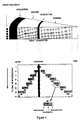
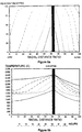
- the optimal placement of the susceptors in the charge is determined and the position of the processing front with time as shown in Figure 3 can be calculated.
- the yield, energy consumption, processing time and susceptor temperature can also be determined.
- a control model can then be developed to determine a time profile of power input for maximum productivity within the processing limits of charge volatility, susceptor temperature and product sintering and fusion.
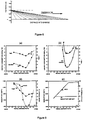
- a 200mm gap to a graphite susceptor will give a Q factor about 10.
- the choice of frequency, susceptor material, refractory and placement of the susceptor is crucial to the satisfactory operation of the furnace.
- Optimum placement which takes into account coupling requirements may place the susceptor further out than the optimum position based on heat transfer requirements alone.
- a portion of the susceptor must be capable of coupling with the induction coils.
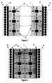
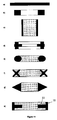
- This coupling position can be part of the conducting portion of the susceptor as in FIGURE 11(b) but to reduce the mass of susceptor in the furnace a configuration as in FIGURE 11 (d) and (h) is preferred.
- the susceptor is formed as a single article to maximise the heat transferred from the coupling portion to the conducting portion.
- the variation in configuration from a solid charge externally heated furnace to an extended ring heated furnace represents an increase in scale of over 100 times for the same maximum heat transfer distance.
Landscapes
- Electromagnetism (AREA)
- Physics & Mathematics (AREA)
- Furnace Housings, Linings, Walls, And Ceilings (AREA)
- Glass Compositions (AREA)
- Steroid Compounds (AREA)
- Manufacture And Refinement Of Metals (AREA)
- Furnace Charging Or Discharging (AREA)
- Fireproofing Substances (AREA)
- Thermal Insulation (AREA)
- Nitrogen Condensed Heterocyclic Rings (AREA)
- Crystals, And After-Treatments Of Crystals (AREA)
- Physical Or Chemical Processes And Apparatus (AREA)
- Furnace Details (AREA)
Claims (16)
- Hochtemperturofen-Anordnung zur Verwendung für die Herstellung von Produkten durch Aufheizen einer Charge (1) von Reaktionspartnern auf eine hohe Temperatur, wobei die Charge (1) und/oder die Produkte eine geringe thermische Leitfähigkeit aufweisen, die Reaktion eine hohe Reaktionstemperatur besitzt, und die Ofen-Anordnung aufweist:- eine Außenwandung (6),- angrenzend zur Außenwandung ein elektromagnetisches Induktionsmittel (3),- eine thermische und elektrische Isolationsschicht (4) zur Isolierung der Induktionsmittel (3) von der Charge (1),- einen Chargenaufnahmeraum innerhalb der Isolationsschicht zur Aufnahme der Charge, und- einen induktiven Suszeptorring (2), der innerhalb einer Charge im Chargenaufnahmeraum so angeordnet ist, daß die Mitte eines Querschnitts durch den Bereich des Suszeptorrings (2) in einer radialen Richtung innerhalb des Bereichs von 30% bis 90% der radialen Entfernung von der Mitte oder des inneren Randes (5) der Charge zum äußeren Rand der Charge liegt,dadurch gekennzeichnet, daß
der induktive Suszeptorring (2) einen Kupplungsbereich (10) und einen sich radial vom Kupplungsbereich (10) erstreckenden Leitungsbereich (11) zur Leitung der durch den Kupplungsbereich (10) erzeugten Wärme in die Charge (1) aufweist, wobei eine fortschreitende Reaktionsfront von vollständig reagiertem Produkt die Mitte oder den inneren Rand der Charge erreicht, bevor sie die äußere Oberfläche der Charge erreicht. - Hochtemperturofen-Anordnung nach Anspruch 1, dadurch gekennzeichnet, daß sie zumindest zwei induktive Suszeptorringe aufweist, von denen jeder so in der Charge angeordnet ist, daß eine von einem der Suszeptorringe ausgehende fortschreitende Reaktionsfront von vollständig reagiertem Produkt oder eine von einem angrenzenden Suszeptorring ausgehende fortschreitende Reaktionsfront von vollständig reagiertem Produkt den inneren Rand (5) der Charge (1) eher erreicht, als die äußere Grenze der Charge (1) erreicht wird.
- Hochtemperturofen-Anordnung nach Anspruch 1 oder 2, dadurch gekennzeichnet, daß die Mitte eines Querschnitts durch den Bereich des Suszeptorrings (2) in einer radialen Richtung innerhalb des Bereichs von 60% bis 85% der radialen Entfernung von der Mitte oder des inneren Randes (5) der Charge zum äußeren Rand der Charge liegt.
- Hochtemperturofen-Anordnung nach Anspruch 1, 2 oder 3, dadurch gekennzeichnet, daß der induktive Suszeptorring (2) als Körper geformt ist, der durch Rotation seiner radialen Querschnittsform bestimmt ist.
- Hochtemperturofen-Anordnung nach einem der vorhergehenden Ansprüche, dadurch gekennzeichnet, daß der Leitungsbereich (11) des Suszeptorrings (2) eine höhere thermische Leitfähigkeit aufweist als die Charge (1) oder das Produkt.
- Hochtemperturofen-Anordnung nach einem der vorhergehenden Ansprüche, dadurch gekennzeichnet, daß sich der Leitungsbereich (11) radial nach innen vom Kupplungsbereich (10) ausgehend erstreckt.
- Hochtemperturofen-Anordnung nach einem der vorhergehenden Ansprüche, dadurch gekennzeichnet, daß der Leitungsbereich (11) und der Kupplungsbereich (10) des Suszeptorrings als einstückiges Bauteil ausgebildet sind.
- Hochtemperturofen-Anordnung nach einem der vorhergehenden Ansprüche, dadurch gekennzeichnet, daß der induktive Syszeptorring oder die -ringe ein Gesamtvolumen von weniger als 20% des Gesamtvolumens der Charge einnehmen.
- Hochtemperturofen-Anordnung nach einem der vorhergehenden Ansprüche, dadurch gekennzeichnet, daß der Chargenaufnahmeraum kreisförmig ausgebildet ist.
- Hochtemperturofen-Anordnung nach Anspruch 9, dadurch gekennzeichnet, daß der Raum in der Mitte des kreisförmigen Chargenaufnahmeraums zur Bildung eines Auslasses unbelegt ist, um Gasen, die während des Betriebs der Ofen-Anordnung entstehen, das Entweichen von der Ofen-Anordnung zu ermöglichen.
- Verfahren zur Steuerung einer Ofen-Anordnung, mit einer Außenwandung (6), angrenzend zu der Außenwandung einem elektromagnetischen Induktionsmittel (3), einer thermischen und elektrischen Isolationsschicht zur Isolierung der Induktionsmittel, einem Chargenaufnahmeraum innerhalb der Isolationsschicht, einer in dem Chargenaufnahmeraum positionierten Charge (1), und einem induktiven Suszeptorring (2), der innerhalb einer Charge in dem Chargenaufnahmeraum so angeordnet ist, daß die Mitte eines Querschnitts durch den Bereich des Suszeptorrings in einer radialen Richtung innerhalb des Bereichs von 30% bis 90% der radialen Entfernung vom inneren Rand (5) der Charge (1) zum äußeren Rand der Charge (1) liegt, wobei das Verfahren dadurch gekennzeichnet ist, daß es die folgenden Schritte aufweist:(i) Erhitzen des induktiven Suszeptorrings (2) auf eine vorbestimmte Temperatur,(ii) Erhöhen der Temperatur des induktiven Suszeptorrings nachdem eine fortschreitende Front eine Zone vollständig reagierten Produkts sich von der Oberfläche des induktiven Suszeptorrings (2) fortbewegt hat, so daß die Temperatur der Charge (1) vor der Front der fortschreitenden Zone unterhalb der vorbestimmten Temperatur bleibt, und(iii) Beibehalten der Temperaturerhöhung des induktiven Suszeptorrings (2), bei Halten der Temperatur vor der Front der fortschreitenden Zone unterhalb der vorbestimmten Temperatur, bis eine Maximaltemperatur des induktiven Suszeptorrings (2) erreicht ist, oder die Front der fortschreitenden Zone den äußeren Rand der Charge (1) erreicht hat.
- Verfahren nach Anspruch 11, dadurch gekennzeichnet, daß der Suszeptorring (2) so positioniert ist, daß die Front der fortschreitenden Zone den inneren Rand (5) der Charge (1) erreicht, bevor der äußere Rand der Charge (1) erreicht wird.
- Verfahren nach Anspruch 11 oder 12, dadurch gekennzeichnet, daß der induktive Suszeptorring (2) als Körper geformt ist, der durch Rotation seiner radialen Querschnittsform bestimmt ist.
- Verfahren nach Anspruch 11, 12 oder 13, dadurch gekennzeichnet, daß der Querschnitt durch den Bereich des Suszeptorrings (2) in einer radialen Richtung innerhalb des Bereichs von 60% bis 85% der radialen Entfernung des inneren Randes (5) der Charge zum äußeren Rand der Charge (1) angeordnet ist.
- Verfahren nach einem der Ansprüche 11 bis 14, dadurch gekennzeichnet, daß der Suszeptorring (2) einen induktiven Kupplungsbereich (10) und einen sich radial vom Kupplungsbereich (10) erstreckenden Leitungsbereich (11) zur Leitung der durch den Kupplungsbereich (10) erzeugten Wärme in die Charge (1) aufweist.
- Verfahren nach einem der Ansprüche 11 bis 15, dadurch gekennzeichnet, daß das Reaktionsprodukt ein Übergangsmetall-Borid ist.
Applications Claiming Priority (3)
| Application Number | Priority Date | Filing Date | Title |
|---|---|---|---|
| AUPJ893190 | 1990-03-05 | ||
| AU8931/90 | 1990-03-05 | ||
| PCT/AU1991/000074 WO1991014353A1 (en) | 1990-03-05 | 1991-03-05 | High temperature furnace |
Publications (3)
| Publication Number | Publication Date |
|---|---|
| EP0518971A1 EP0518971A1 (de) | 1992-12-23 |
| EP0518971A4 EP0518971A4 (en) | 1993-02-24 |
| EP0518971B1 true EP0518971B1 (de) | 1997-01-22 |
Family
ID=3774531
Family Applications (1)
| Application Number | Title | Priority Date | Filing Date |
|---|---|---|---|
| EP91905980A Expired - Lifetime EP0518971B1 (de) | 1990-03-05 | 1991-03-05 | Hochtemperaturofen |
Country Status (9)
| Country | Link |
|---|---|
| EP (1) | EP0518971B1 (de) |
| AT (1) | ATE148296T1 (de) |
| BR (1) | BR9106141A (de) |
| CA (1) | CA2077669C (de) |
| DE (1) | DE69124367T2 (de) |
| IS (1) | IS3679A7 (de) |
| NO (1) | NO302270B1 (de) |
| NZ (1) | NZ237315A (de) |
| WO (1) | WO1991014353A1 (de) |
Families Citing this family (3)
| Publication number | Priority date | Publication date | Assignee | Title |
|---|---|---|---|---|
| GB9717880D0 (en) * | 1997-08-23 | 1997-10-29 | Coreflux Systems International | Electromagnetic fluid heater |
| DE102007050010A1 (de) * | 2007-10-17 | 2009-06-25 | Jan-Philipp Mai | Verfahren und Vorrichtung zur Herstellung von Silizium |
| CN108731475B (zh) * | 2017-04-20 | 2019-10-18 | 南京理工大学 | 一种陶瓷材料微波烧结用保温装置 |
Family Cites Families (6)
| Publication number | Priority date | Publication date | Assignee | Title |
|---|---|---|---|---|
| US1794863A (en) * | 1928-08-03 | 1931-03-03 | Ajax Electrothermic Corp | Electric-furnace method |
| GB891263A (en) * | 1959-04-22 | 1962-03-14 | Glyco Metall Werke | Process and apparatus for the regulatable, continuous melting down of metal chips |
| US3036888A (en) * | 1959-12-29 | 1962-05-29 | Norton Co | Process for producing titanium nitride |
| GB1430382A (en) * | 1972-02-23 | 1976-03-31 | Electricity Council | Methods of melting glass |
| GB2082879A (en) * | 1980-08-20 | 1982-03-10 | Plessey Co Ltd | Improvements in or relating to furnaces for producing semiconductor materials |
| FR2531062A2 (fr) * | 1981-11-06 | 1984-02-03 | Saphymo Stel | Dispositif de fusion par induction directe de substances dielectriques du genre verres ou emaux |
-
1991
- 1991-03-04 IS IS3679A patent/IS3679A7/is unknown
- 1991-03-05 EP EP91905980A patent/EP0518971B1/de not_active Expired - Lifetime
- 1991-03-05 CA CA002077669A patent/CA2077669C/en not_active Expired - Lifetime
- 1991-03-05 DE DE69124367T patent/DE69124367T2/de not_active Expired - Lifetime
- 1991-03-05 NZ NZ237315A patent/NZ237315A/xx unknown
- 1991-03-05 WO PCT/AU1991/000074 patent/WO1991014353A1/en not_active Ceased
- 1991-03-05 BR BR919106141A patent/BR9106141A/pt not_active IP Right Cessation
- 1991-03-05 AT AT91905980T patent/ATE148296T1/de active
-
1992
- 1992-09-04 NO NO923458A patent/NO302270B1/no unknown
Also Published As
| Publication number | Publication date |
|---|---|
| BR9106141A (pt) | 1993-03-09 |
| EP0518971A1 (de) | 1992-12-23 |
| WO1991014353A1 (en) | 1991-09-19 |
| IS3679A7 (is) | 1991-09-06 |
| NO923458L (no) | 1992-11-02 |
| NO302270B1 (no) | 1998-02-09 |
| ATE148296T1 (de) | 1997-02-15 |
| DE69124367T2 (de) | 1997-05-28 |
| CA2077669A1 (en) | 1991-09-06 |
| NZ237315A (en) | 1993-04-28 |
| CA2077669C (en) | 1999-09-28 |
| NO923458D0 (no) | 1992-09-04 |
| EP0518971A4 (en) | 1993-02-24 |
| DE69124367D1 (de) | 1997-03-06 |
Similar Documents
| Publication | Publication Date | Title |
|---|---|---|
| US5502743A (en) | High temperature furnace | |
| CA1102886A (en) | Arc heater method for the production of single crystal silicon | |
| JP4593109B2 (ja) | 金属を溶融させる方法及び装置 | |
| Hassine et al. | Synthesis of refractory metal carbide powders via microwave carbothermal reduction | |
| AU2002363728A1 (en) | Method and apparatus for melting metals | |
| US20080298425A1 (en) | Method and apparatus for melting metals using both alternating current and direct current | |
| EP0518971B1 (de) | Hochtemperaturofen | |
| CN109368644A (zh) | 一种制备碳氮化硅的方法 | |
| AU647785B2 (en) | High temperature furnace | |
| JP2579561B2 (ja) | SiCウイスカーの製造装置 | |
| US3504093A (en) | Induction furnace apparatus for the manufacture of metal carbide | |
| RU2404272C1 (ru) | Устройство для одновременного получения тугоплавких металлических и неметаллических материалов и возгонов | |
| US3549353A (en) | Method and apparatus for melting reactive materials | |
| Wroe | Microwave-assisted firing of ceramics | |
| JPH11278819A (ja) | 粉末カーボン連続焼成方法およびその装置 | |
| US3609199A (en) | Push-through furnace with graphite rod heating | |
| WO2006088037A1 (ja) | シリコン鋳造装置およびシリコン基板の製造方法 | |
| SU55959A1 (ru) | Способ получени карбидов бора, кремни и титана | |
| US20060091134A1 (en) | Method and apparatus for heating refractory oxides | |
| JP3081110B2 (ja) | 電磁誘導加熱炉 | |
| US4698481A (en) | Method for preventing decomposition of silicon carbide articles during high temperature plasma furnace sintering | |
| JPH03117882A (ja) | 金属酸化物の炭素熱還元用開放アーク炉 | |
| JP2001139374A (ja) | 被加熱物の熱処理方法 | |
| Moore et al. | Method and apparatus for melting metals | |
| Kroll et al. | Graphite-rod hairpin-resistor radiation furnace for high temperatures |
Legal Events
| Date | Code | Title | Description |
|---|---|---|---|
| PUAI | Public reference made under article 153(3) epc to a published international application that has entered the european phase |
Free format text: ORIGINAL CODE: 0009012 |
|
| 17P | Request for examination filed |
Effective date: 19920929 |
|
| AK | Designated contracting states |
Kind code of ref document: A1 Designated state(s): AT BE CH DE DK ES FR GB GR IT LI LU NL SE |
|
| A4 | Supplementary search report drawn up and despatched |
Effective date: 19930107 |
|
| AK | Designated contracting states |
Kind code of ref document: A4 Designated state(s): AT BE CH DE DK ES FR GB GR IT LI LU NL SE |
|
| 17Q | First examination report despatched |
Effective date: 19931022 |
|
| GRAG | Despatch of communication of intention to grant |
Free format text: ORIGINAL CODE: EPIDOS AGRA |
|
| GRAH | Despatch of communication of intention to grant a patent |
Free format text: ORIGINAL CODE: EPIDOS IGRA |
|
| GRAH | Despatch of communication of intention to grant a patent |
Free format text: ORIGINAL CODE: EPIDOS IGRA |
|
| GRAA | (expected) grant |
Free format text: ORIGINAL CODE: 0009210 |
|
| AK | Designated contracting states |
Kind code of ref document: B1 Designated state(s): AT BE CH DE DK ES FR GB GR IT LI LU NL SE |
|
| PG25 | Lapsed in a contracting state [announced via postgrant information from national office to epo] |
Ref country code: IT Free format text: LAPSE BECAUSE OF FAILURE TO SUBMIT A TRANSLATION OF THE DESCRIPTION OR TO PAY THE FEE WITHIN THE PRE;WARNING: LAPSES OF ITALIAN PATENTS WITH EFFECTIVE DATE BEFORE 2007 MAY HAVE OCCURRED AT ANY TIME BEFORE 2007. THE CORRECT EFFECTIVE DATE MAY BE DIFFERENT FROM THE ONE RECORDED.SCRIBED TIME-LIMIT Effective date: 19970122 Ref country code: AT Effective date: 19970122 Ref country code: LI Free format text: LAPSE BECAUSE OF FAILURE TO SUBMIT A TRANSLATION OF THE DESCRIPTION OR TO PAY THE FEE WITHIN THE PRESCRIBED TIME-LIMIT Effective date: 19970122 Ref country code: BE Effective date: 19970122 Ref country code: CH Free format text: LAPSE BECAUSE OF FAILURE TO SUBMIT A TRANSLATION OF THE DESCRIPTION OR TO PAY THE FEE WITHIN THE PRESCRIBED TIME-LIMIT Effective date: 19970122 Ref country code: GR Free format text: LAPSE BECAUSE OF FAILURE TO SUBMIT A TRANSLATION OF THE DESCRIPTION OR TO PAY THE FEE WITHIN THE PRESCRIBED TIME-LIMIT Effective date: 19970122 Ref country code: DK Effective date: 19970122 Ref country code: ES Free format text: THE PATENT HAS BEEN ANNULLED BY A DECISION OF A NATIONAL AUTHORITY Effective date: 19970122 |
|
| REF | Corresponds to: |
Ref document number: 148296 Country of ref document: AT Date of ref document: 19970215 Kind code of ref document: T |
|
| REG | Reference to a national code |
Ref country code: CH Ref legal event code: EP |
|
| REF | Corresponds to: |
Ref document number: 69124367 Country of ref document: DE Date of ref document: 19970306 |
|
| PG25 | Lapsed in a contracting state [announced via postgrant information from national office to epo] |
Ref country code: LU Free format text: LAPSE BECAUSE OF NON-PAYMENT OF DUE FEES Effective date: 19970331 |
|
| PG25 | Lapsed in a contracting state [announced via postgrant information from national office to epo] |
Ref country code: SE Effective date: 19970422 |
|
| ET | Fr: translation filed | ||
| REG | Reference to a national code |
Ref country code: CH Ref legal event code: PL |
|
| PLBE | No opposition filed within time limit |
Free format text: ORIGINAL CODE: 0009261 |
|
| STAA | Information on the status of an ep patent application or granted ep patent |
Free format text: STATUS: NO OPPOSITION FILED WITHIN TIME LIMIT |
|
| 26N | No opposition filed | ||
| REG | Reference to a national code |
Ref country code: GB Ref legal event code: IF02 |
|
| PGFP | Annual fee paid to national office [announced via postgrant information from national office to epo] |
Ref country code: GB Payment date: 20080305 Year of fee payment: 18 |
|
| PGFP | Annual fee paid to national office [announced via postgrant information from national office to epo] |
Ref country code: FR Payment date: 20080311 Year of fee payment: 18 |
|
| PGFP | Annual fee paid to national office [announced via postgrant information from national office to epo] |
Ref country code: NL Payment date: 20090303 Year of fee payment: 19 |
|
| GBPC | Gb: european patent ceased through non-payment of renewal fee |
Effective date: 20090305 |
|
| REG | Reference to a national code |
Ref country code: FR Ref legal event code: ST Effective date: 20091130 |
|
| PG25 | Lapsed in a contracting state [announced via postgrant information from national office to epo] |
Ref country code: FR Free format text: LAPSE BECAUSE OF NON-PAYMENT OF DUE FEES Effective date: 20091123 Ref country code: GB Free format text: LAPSE BECAUSE OF NON-PAYMENT OF DUE FEES Effective date: 20090305 |
|
| PGFP | Annual fee paid to national office [announced via postgrant information from national office to epo] |
Ref country code: DE Payment date: 20100329 Year of fee payment: 20 |
|
| REG | Reference to a national code |
Ref country code: NL Ref legal event code: V1 Effective date: 20101001 |
|
| PG25 | Lapsed in a contracting state [announced via postgrant information from national office to epo] |
Ref country code: NL Free format text: LAPSE BECAUSE OF NON-PAYMENT OF DUE FEES Effective date: 20101001 |
|
| REG | Reference to a national code |
Ref country code: DE Ref legal event code: R071 Ref document number: 69124367 Country of ref document: DE |
|
| PG25 | Lapsed in a contracting state [announced via postgrant information from national office to epo] |
Ref country code: DE Free format text: LAPSE BECAUSE OF EXPIRATION OF PROTECTION Effective date: 20110305 |